EP1129967A2 - Système de préhension pour l' enlèvement automatique des objets plats en piles d' un emballage de transport - Google Patents
Système de préhension pour l' enlèvement automatique des objets plats en piles d' un emballage de transport Download PDFInfo
- Publication number
- EP1129967A2 EP1129967A2 EP01103940A EP01103940A EP1129967A2 EP 1129967 A2 EP1129967 A2 EP 1129967A2 EP 01103940 A EP01103940 A EP 01103940A EP 01103940 A EP01103940 A EP 01103940A EP 1129967 A2 EP1129967 A2 EP 1129967A2
- Authority
- EP
- European Patent Office
- Prior art keywords
- rod
- flat goods
- flat
- acting
- side wings
- Prior art date
- Legal status (The legal status is an assumption and is not a legal conclusion. Google has not performed a legal analysis and makes no representation as to the accuracy of the status listed.)
- Granted
Links
- 238000004806 packaging method and process Methods 0.000 claims abstract description 76
- 238000000034 method Methods 0.000 description 13
- 230000008569 process Effects 0.000 description 13
- 238000011161 development Methods 0.000 description 12
- 230000018109 developmental process Effects 0.000 description 12
- 238000000926 separation method Methods 0.000 description 4
- 230000006835 compression Effects 0.000 description 3
- 238000007906 compression Methods 0.000 description 3
- 230000008878 coupling Effects 0.000 description 3
- 238000010168 coupling process Methods 0.000 description 3
- 238000005859 coupling reaction Methods 0.000 description 3
- 230000000694 effects Effects 0.000 description 3
- 239000000463 material Substances 0.000 description 3
- 230000002787 reinforcement Effects 0.000 description 3
- 238000012549 training Methods 0.000 description 3
- 230000005484 gravity Effects 0.000 description 2
- 230000003993 interaction Effects 0.000 description 2
- 230000007246 mechanism Effects 0.000 description 2
- 230000004048 modification Effects 0.000 description 2
- 238000012986 modification Methods 0.000 description 2
- 230000001953 sensory effect Effects 0.000 description 2
- 230000005540 biological transmission Effects 0.000 description 1
- 230000008859 change Effects 0.000 description 1
- 238000005520 cutting process Methods 0.000 description 1
- 238000000151 deposition Methods 0.000 description 1
- 238000005553 drilling Methods 0.000 description 1
- 238000005516 engineering process Methods 0.000 description 1
- 238000000605 extraction Methods 0.000 description 1
- 239000000835 fiber Substances 0.000 description 1
- 238000005429 filling process Methods 0.000 description 1
- 230000006872 improvement Effects 0.000 description 1
- 238000004519 manufacturing process Methods 0.000 description 1
- 239000002985 plastic film Substances 0.000 description 1
- 229920006255 plastic film Polymers 0.000 description 1
- 238000003825 pressing Methods 0.000 description 1
- 238000007639 printing Methods 0.000 description 1
- 230000008439 repair process Effects 0.000 description 1
- 238000003860 storage Methods 0.000 description 1
- 230000002123 temporal effect Effects 0.000 description 1
- 238000012546 transfer Methods 0.000 description 1
Images




Classifications
-
- B—PERFORMING OPERATIONS; TRANSPORTING
- B65—CONVEYING; PACKING; STORING; HANDLING THIN OR FILAMENTARY MATERIAL
- B65G—TRANSPORT OR STORAGE DEVICES, e.g. CONVEYORS FOR LOADING OR TIPPING, SHOP CONVEYOR SYSTEMS OR PNEUMATIC TUBE CONVEYORS
- B65G61/00—Use of pick-up or transfer devices or of manipulators for stacking or de-stacking articles not otherwise provided for
-
- B—PERFORMING OPERATIONS; TRANSPORTING
- B65—CONVEYING; PACKING; STORING; HANDLING THIN OR FILAMENTARY MATERIAL
- B65B—MACHINES, APPARATUS OR DEVICES FOR, OR METHODS OF, PACKAGING ARTICLES OR MATERIALS; UNPACKING
- B65B69/00—Unpacking of articles or materials, not otherwise provided for
-
- B—PERFORMING OPERATIONS; TRANSPORTING
- B65—CONVEYING; PACKING; STORING; HANDLING THIN OR FILAMENTARY MATERIAL
- B65G—TRANSPORT OR STORAGE DEVICES, e.g. CONVEYORS FOR LOADING OR TIPPING, SHOP CONVEYOR SYSTEMS OR PNEUMATIC TUBE CONVEYORS
- B65G47/00—Article or material-handling devices associated with conveyors; Methods employing such devices
- B65G47/74—Feeding, transfer, or discharging devices of particular kinds or types
- B65G47/90—Devices for picking-up and depositing articles or materials
Definitions
- the invention relates to a gripper system for gripping flat, in one Rod-like alignment aligned along a y-direction arranged goods, especially pre-glued, flat-lying folding boxes, with drive and guide elements for a holding device, those in the y direction and in at least one x direction perpendicular to y-direction a defined force on the rod-like, can exercise flat goods, the elements acting in the y direction the holding device can be moved linearly parallel to the y direction and the in x-direction elements include a pair of side wings that face up two opposite sides with respect to a y-axis of the device are arranged
- a disadvantage of the known gripper system is that it is imperative a device for generating negative pressure is required to cover the flat To let suction unit take effect in the holding direction. Since the As a rule, negative pressure cannot be generated on the gripper system itself, a suction line to the gripper system must be located from a remote location installed that are designed to be flexible and flexible must, so that the gripper from the positioning system actually any desired Destinations transported and always the required vacuum can be kept ready for the suction device to take effect.
- US-A 4,538,511 is a simpler one, only with mechanical ones Holding devices equipped gripper system known with which is also a string of flat goods like Folding boxes can be removed from containers and transported.
- these containers are not an outer carton, as he usually uses as transport packaging for folding boxes is, but around specially prepared, laterally open containers in an automated transport system. Removing a folding box bar from a usual carton with the known system not possible.
- the object of the present invention is therefore a gripper system of the beginning to introduce the type mentioned, with the simplest possible technical Means is modified so that it without special requirements for the Edge contour of the flat goods and with high format variability the automatic Removing bars of flat goods from an open outer packaging as well as their gentle and fail-safe transport to one allows any destination in the vicinity, including the removal parts of the outer packaging in the way, such as lids, intermediate layers, Blisters etc. do not interfere with the fully automatic removal process should, and the possibility of removal no longer required parts of the outer packaging should be given.
- this object is achieved in that the in elements acting in the x direction about an axis parallel to the y direction are pivotable, and after a corresponding pivoting in each case a force acting in the x direction or in the x direction on the rod of flat Goods can exercise that the side wings regardless of the in elements acting in the y direction of the holding device along one to the y and linearly movable to the x-direction and at least in the z-axis two axial positions along the z-direction can be seen that the side wings are designed so that they also exert a force on the Can exercise rod of flat goods, which are independent of the in z-direction acting weight force of the rod from flat goods, and that the side wings comprise a gripping unit acting in the z direction, with which, for example, covers the bar of flat goods upwards Intermediate layer and / or an outer packaging or transport packaging and / or a blister can be gripped.
- the automatic removal device is also that there is, for example, no special separating finger for removal of the packed goods from the outer packaging.
- the device according to the invention evenly in the x direction and in the associated Opposite direction a dosing holding force on the rod of flat Exercise goods, due to the provided according to the invention Swiveling movement of the side wings (instead of a linear movement in x-direction) a space-saving gripping at different heights (ie z positions) is made possible without the side wings in their extreme positions take up too much space in the x direction.
- this is a Alignment of the rod possible before the actual removal.
- the side wings Due to the possibility of the side wings in the z direction independently of the to move elements of the holding device acting in the y direction, so the side wings can be used in addition to the gripping and securing function also perform a directional function in relation to the bar of flat goods.
- the active force transmission in the z direction regardless of the corresponding one Gravity component of the flat goods also enables alignment the rod in the z direction as well as a high degree of variability of the gripper system according to the invention with regard to the outer contour of the to be removed Goods.
- a pivotable, laterally in recesses in the edge contour of flat Intervening element as such is known per se from the DE 42 08 450 A1.
- the Side wings have angled holding jaws with which they move in the z direction exert a holding force on the bar of flat goods. Thereby can fall out with technically particularly simple means gripped flat goods in the z direction when moving the gripped goods Rod can be prevented safely.
- the gripper unit is a suction device has, which is connected to a system for generating negative pressure is, and with which in particular an intermediate layer is sucked in the z direction and can be held.
- the suction cup Have suction cups for gripping the intermediate layer, with which one Particularly precise positioning of the connection point between the gripper and outer surface of the outer packaging is made possible.
- Suction devices as such are in connection with gripper systems known per se from the prior art.
- the gripper unit at least one mechanical Have grippers, which include in particular the intermediate layer and can hold by pressing.
- a mechanical gripper for intermediate layers is known per se from DE 196 35 433 A1 already cited above.
- the gripping unit can also be used as an alternative or in addition in the case of further developments have at least one drilling gripper that drills an intermediate layer, reach behind and hold the liner.
- the device provides that parts of the overpack, especially the Intermediate layers of magnetic or magnetizable material, preferably in the form of fibers or platelets worked into the surface, and that the gripping unit has at least one magnetic gripper that this Magnetically attract and hold parts.
- a particularly advantageous embodiment of the device according to the invention is characterized in that the elements acting in the y direction a pair of oppositely arranged with respect to the z-axis Include gripping jaws that are linearly movable along a y-axis and in at least two axial positions with respect to the y direction can be determined are. This makes it particularly easy to pre-compress and then compress Compress the rod from flat goods before the actual one Remove from the outer packaging, which increases reliability and reproducibility of the removal process is further increased.
- the gripping jaws Have holding parts that are parallel to the x direction about an axis are pivotable.
- the opposite holding parts a force in a position parallel or rotated about the x direction Exercise in the y direction on the flat goods bar. When dropping it can be used to create any scale position for flat goods.
- DE 24 40 199 A1 describes a gripper system with a pivotable and linear one movable gripping jaws or holding parts can be removed, which, however, in the rest no further similarities with the gripper system according to the invention having.
- Another preferred embodiment of the device according to the invention is characterized in that a linearly movable in the z direction or provided a pressure plate pivotable about an axis parallel to the x direction with which pressure is exerted against a gripped bar made of flat goods can be exercised in the z direction. With this pressure plate the rod pressed out of flat goods during unloading to get out of the gripper system to be removed. In addition, the possibility of the defined Lay down the bar of flat goods in the form of scales even further be improved.
- the pressure plate on its in the appropriate operating state Rod from flat goods side has a suction device, which is connected to a system for generating negative pressure, and with which, in particular, the rod of flat goods or the same the intermediate layer covering the top is sucked in in the z direction and can be held.
- a suction pad can be particularly a detachable binding on the top of the corresponding is easy and precise Produce the surface of the bar from flat goods.
- the gripper system has a base body on which the side wings and if necessary the gripping jaws and the pressure plate are movably attached, and that the base body at its in the operating state one side of the bar of flat goods has several surfaces with a concave contour, to which the rod of flat Goods in the gripped state in the z direction.
- the gripper system according to the invention for removal of bars of pre-glued, flat-lying folding boxes from their outer packaging due to the special structure of the product, there is an undefined unstable behavior, which leads to the folding boxes from the Break out the bar up or down or form an S shape.
- a device for automatic Format adjustment of the gripper system to the bars to be gripped flat goods It can be used immediately without any time-consuming modifications from unloading one format to unloading another format be passed over.
- a separating finger can also be provided, with which one a suitable space for gripping a bar of flat goods between the bar of flat goods and one surrounding them Outer packaging or transport packaging can be created.
- the gripper system is part of an automatic one Handling or robot systems for automated filling and / or Removing bars of flat goods in or from an outer packaging or Transport packaging.
- an automatic handling system in the Connection with a filling and removal device is, for example described in DE 197 20 650 A1 cited above.
- the robot controller of drive and guide elements enables a particularly flexible Use of the device according to the invention even with larger differences in the outer geometry of the outer packaging to be emptied and the bars of flat goods to be removed.
- the gripper system is advantageously or robot system mechanically, energetically and possibly sensory detachable.
- it opens up thus the possibility of differently designed tools, for example for automatically opening the outer packaging or in other places of the gripper system.
- This also results in the Possibility to use a tandem process in which an already filled gripper is unloaded while an empty one is being filled, with which further cycle time gains can be achieved.
- further training is particularly preferred of which several differently designed gripper systems are provided, of which at least one to the handling or robot system during operation coupled and at least one gripper system from the handling or. Robot system are disconnected. This allows a fully automatic Changing the gripper systems when the outer contours of the outer packaging to be emptied as well as the flat goods contained therein effect without the use of wage-intensive operating personnel would be required.
- Handling or robot system comprises a robot cell, the two Main functional systems acts, namely a first axis system, which the gripper system in or out of the work area of a second axis system moves that an opening and preferably also dismantling an outer packaging or transport packaging that causes the Contains bars of flat goods.
- This also allows the supply of opening and dismantling packaging is done fully automatically.
- the dismantled parts of the outer packaging can be easily be removed from the working area of the second axis system.
- An embodiment of the device according to the invention is particularly preferred, in which a device for automatic opening and preferably also disassembly of an outer packaging or transport packaging is provided, which contains the bars to be gripped from flat goods.
- a further development of this form of training is characterized in that a conveyor device is provided which the outer packaging in one from the handling or robot system and / or from the positioning system Feed the specified cycle into the working area of the first axis system can, making the cycle time of the entire facility practically permanent of the opening and dismantling process is reduced.
- a further development of this embodiment provides that the handling or robot system in synchronization with the removal of the filling material from the packaging the side surfaces and or the front surfaces of the Packaging can pivot such that the removal device convenient access to the packaging is opened.
- the synchronization can be set so that the disassembly of the outer packaging simultaneously The filling material is removed, or else in a definable time Distance before or after.
- a preferred embodiment of the device according to the invention stipulates that a horizontal Attach pivoting front reinforcement flaps, which in the assembled state attached to the front surfaces, in particular glued or are bracketed, and that the handling or robot system Detachment device for releasing the reinforcement flaps from the front surfaces includes.
- the separator for releasing the reinforcement flaps can in particular be identical to the above-mentioned separation device to release the fixed connection caused by fasteners.
- one or more lid flaps are provided in the outer packaging, which the packaging by pivoting about a horizontal articulation axis and Fasten to a side surface and / or a front surface, and if the handling or robot system is a separation device to release the fastening of the lid flaps from the side and / or Front surfaces includes.
- the separation device can be identical with the breaker mentioned above, if the latter is appropriate is universally structured.
- the holder comprises a pair of opposed with respect to the y-axis arranged side wings 2a, 2b, which by one to y-direction parallel axis are pivotable. This can be used in the x direction a force can be exerted on the rod 1.
- this force is transmitted by two at the lower end of the side wings 2a, 2b attached holding jaws 3a, 3b, which by means of an adjusting device 4a, 4b can be set to different formats of the goods to be gripped can.
- the side wings 2a, 2b are independent of the in elements of the holding device acting in the y direction along the z direction linearly movable and lockable in at least two axial positions.
- Fig. 1 One of these axial positions is shown in Fig. 1, where the rod 1 from the x direction and the -x direction is centered.
- the side wings 2a, 2b are in a further axial position with respect the x-axis, in which they are held by means of the holding jaws 3a, 3b Grasp rod 1 from below and additionally hold in the z direction exert on the rod 1, regardless of the one acting in the z direction Component of the weight of the rod 1 is.
- the side wings 2a, 2b comprise one which acts in the z direction Gripping unit with which, in particular, the rod 1 is made of flat goods Intermediate layer 6 covering the top can be gripped and held.
- the Gripping unit on a suction device 5a, 5b, which is connected to a system for generation of negative pressure is connected, and with that in the operating position 2, the intermediate layer 6 can be sucked in from above.
- the gripping unit cannot in the drawing illustrated embodiments but also a mechanical gripper, a drill gripper, a magnetic gripper or another type of gripper.
- the longitudinal linear movement of the y-axis and in at least two axial positions are noticeable.
- the gripping jaws 7a, 7b have in their lower area Holding parts 8a, 8b, which in turn about an axis parallel to the x direction are pivotable.
- the holding parts 8a, 8b are around a coupling quadrilateral built lever mechanism pivotably and independently pivotable from each other.
- a linear movement in the z direction is possible on the base body 10 and / or printing plate pivotable about an axis parallel to the x direction 9 provided with which against the rod 1 from flat goods a pressure in z-direction (more precisely in the opposite direction) can be.
- the pressure plate 9 has embodiments on its side facing the rod 1 Side also a suction device with which a suction force in z direction can be exercised.
- Fig. 3 shows a gripper system according to the invention when engaging in an outer packaging 11, from which the rod 1 is pulled out in the z direction shall be.
- the outer packaging 11 is one of elements Device 12 for automatic opening and preferably also disassembly the outer packaging 11 pulled apart, so that the invention Immerse the gripper system in the outer packaging 11 from above without any problems can.
- the gripper system according to the invention is preferably connected to one in the drawing Electronically controlled positioning system, not shown coupled for automatic spatial positioning of the gripper system.
- the gripper system is part of an automatic handling or robot systems for the automated removal of bars 1 flat goods from an outer packaging 11.
- the gripper system according to the invention can be mechanically, energetically and sensory to the handling or robot system or to the positioning system, or decoupled from it become.
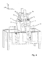
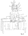
- FIG. 4 to 6 and 8 is the interaction of the invention Gripper system with the device 12 for automatic opening and Disassembly of the outer packaging 11 shown.
- the robot system mentioned above namely comprises a robot cell with at least two main functional systems acts, namely a first axis system, which the Gripper system in or out of the work area of a second axis system moves, which the device 12 for automatic opening and Disassembly of the outer packaging 11 contains.
- the gripper system according to the invention is in its starting position in the basic position above the removal position. After the one with the filled outer packaging to be taken in the device 12 and, as mentioned above, has been opened, the removal process can kick off.
- the gripper system moves from above into the outer packaging 11 as shown in FIG. 4.
- the gripping jaws 7a, 7b By linear movement of the gripping jaws 7a, 7b towards each other along the y direction and the y direction the cartons of rod 1 are first pre-compressed. After that follows the centric already described above in connection with FIG. 1 Straighten by fitting the side wings 2a, 2b from the x or -x direction against the corresponding side surfaces of the rod 1. So the rod 1 is aligned centrally to the entire gripper system, whereby falling out due to the pre-compression with the aid of the gripping jaws 7a, 7b is prevented by individual folding boxes from the rod 1.
- the folding box bar 1 is used the gripping jaws 7a, 7b are continuously compressed until a defined maximum Compression is reached.
- the rod 1 bends like a bridge upwards and comes to rest on a lower surface of the base body 10, which is preferably due to a concave contour to the arch shape of the folding box 1 is adapted so that individual boxes fall out the rod 1 is prevented.
- the gripper system with the grasped folding box rod 1 is after raised in the z direction at the top, and the side wings 7a, 7b simultaneously in the Moved in the opposite direction and against the rod 1 about the y-axis pivoted so that the holding jaws 3a, 3b the rod 1 also from below reach around in the z direction, as shown in FIG. 2. So that's the bar 1 secured for transport from all sides and can be removed from the outer packaging 11 easily removed and transported to any destination.
- the layers are usually one from the other separating intermediate layer 6 by means of the suction device described above 5a, 5b sucked in, likewise removed from the outer packaging 11 and transported away by the gripper system according to the invention, as in Fig. 5 shown spatially.
- the intermediate layer 6 is thrown off over a defined storage position, before the gripper system the removed folding box rod 1 on their Destination, for example a conveyor 13 transported where it is then is stored in a defined manner, as shown in FIG. 6.
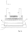
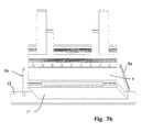
- the side wings 2a, 2b are first pivoted about the y axis and opened upwards so that the transport lock of the rod 1 is solved. Then the gripper system is lowered in the -z direction and the Compression by moving the gripping jaws 7a, 7b in the y or y direction solved.
- a defined, desired scale direction for example, asymmetrical Actuation of the holding parts 8a, 8b are effected, so that the folding boxes from the rod 1 now in a scale position 1 'in a precisely predetermined Position and orientation are stored.
- the gripper system can then start the extraction cycle again, as shown in Fig. 8, where the system in turn opens the outer carton 11 is retracted on the device 12 from above to the next Layer of folding boxes in the form of a bar and, if necessary, another intermediate layer 6 can be removed and removed.
Landscapes
- Engineering & Computer Science (AREA)
- Mechanical Engineering (AREA)
- Manipulator (AREA)
- Control And Other Processes For Unpacking Of Materials (AREA)
Applications Claiming Priority (2)
| Application Number | Priority Date | Filing Date | Title |
|---|---|---|---|
| DE10010100A DE10010100A1 (de) | 2000-03-02 | 2000-03-02 | Greifersystem zur automatischen Entnahme von Stangen flacher Güter aus einer Transportverpackung |
| DE10010100 | 2000-03-02 |
Publications (3)
| Publication Number | Publication Date |
|---|---|
| EP1129967A2 true EP1129967A2 (fr) | 2001-09-05 |
| EP1129967A3 EP1129967A3 (fr) | 2002-08-14 |
| EP1129967B1 EP1129967B1 (fr) | 2004-01-21 |
Family
ID=7633191
Family Applications (1)
| Application Number | Title | Priority Date | Filing Date |
|---|---|---|---|
| EP01103940A Expired - Lifetime EP1129967B1 (fr) | 2000-03-02 | 2001-02-19 | Système de préhension pour l' enlèvement automatique des objets plats en piles d' un emballage de transport |
Country Status (3)
| Country | Link |
|---|---|
| EP (1) | EP1129967B1 (fr) |
| AT (1) | ATE258138T1 (fr) |
| DE (2) | DE10010100A1 (fr) |
Cited By (6)
| Publication number | Priority date | Publication date | Assignee | Title |
|---|---|---|---|---|
| WO2002062684A1 (fr) * | 2000-12-20 | 2002-08-15 | Outokumpu Oyj | Agencement permettant de transporter un produit de type plaque d'un emplacement a un autre |
| CN107265119A (zh) * | 2017-08-08 | 2017-10-20 | 无锡先导智能装备股份有限公司 | 一种集成有盖板抓取机构的搬运机构及搬运方法 |
| CN109606876A (zh) * | 2018-12-27 | 2019-04-12 | 重庆市灵龙自动化设备有限公司 | 具有矫正及开盒功能的传送线 |
| CN117585453A (zh) * | 2024-01-18 | 2024-02-23 | 常州市力烨重型设备科技有限公司 | 一种自走式太阳能板安装设备 |
| CN118061146A (zh) * | 2024-04-17 | 2024-05-24 | 洛阳圣鑫重工科技有限公司 | 一种电力检测设备存放装置及电力设备检测车 |
| CN119527673A (zh) * | 2025-01-10 | 2025-02-28 | 山东鲁舜生物科技有限公司 | 一种微量元素肥料生产用投料设备 |
Families Citing this family (1)
| Publication number | Priority date | Publication date | Assignee | Title |
|---|---|---|---|---|
| CN111301770A (zh) * | 2019-12-19 | 2020-06-19 | 上海世迈自动化设备有限公司 | 一片式纸箱裹包机用抓取结构 |
Citations (10)
| Publication number | Priority date | Publication date | Assignee | Title |
|---|---|---|---|---|
| DE2440199A1 (de) | 1974-08-22 | 1976-03-04 | 4 P Verpackungen Gmbh | Packzange |
| US4538511A (en) | 1983-08-24 | 1985-09-03 | Harris Graphics Corporation | Signature handling apparatus |
| DE3718601A1 (de) | 1987-06-03 | 1988-12-22 | Bat Cigarettenfab Gmbh | Vorrichtung zum abheben mindestens eines material-stapels |
| US4943206A (en) | 1988-06-16 | 1990-07-24 | Konica Corporation | Automatic carton supply method |
| DE4208405A1 (de) | 1992-03-16 | 1993-09-23 | Silitek Corp | Notebookcomputer-cmos-firmware-verarbeitungsverfahren und zugehoerige hardware |
| DE4208450A1 (de) | 1992-03-17 | 1993-09-23 | Iwk Verpackungstechnik Gmbh | Vorrichtung und verfahren zum beschicken einer verpackungsmaschine mit faltschachteln |
| DE19635433A1 (de) | 1996-09-02 | 1998-03-05 | Bosch Gmbh Robert | Vorrichtung zum Überführen von flachliegenden Faltschachtelzuschnitten aus einer Umverpackung in eine Zuführeinrichtung einer Kartoniermaschine |
| DE19720650A1 (de) | 1997-05-16 | 1998-11-19 | Faller Kg August | Befüll- und Entnahmeeinrichtung für flache Güter und Betriebsverfahren |
| DE19720710C2 (de) | 1997-05-16 | 1999-09-23 | Edelmann Carl Gmbh | Greifersystem zum Greifen von flachen Gütern und Betriebsverfahren |
| US5984623A (en) | 1998-03-31 | 1999-11-16 | Abb Flexible Automation, Inc. | Carrier feed vaccum gripper |
Family Cites Families (3)
| Publication number | Priority date | Publication date | Assignee | Title |
|---|---|---|---|---|
| FR2556701B1 (fr) * | 1983-12-14 | 1989-05-19 | Loiseau Joseph | Dispositif de prehension d'objets ou d'animaux permettant leur convoyage en position suspendue |
| DE3541900A1 (de) * | 1985-11-27 | 1987-06-04 | Walter Lauermann | Verfahren und vorrichtung zum lagenweisen versetzen von gleichgrossen stangen |
| IT1263434B (it) * | 1993-06-16 | 1996-08-05 | Gd Spa | Unita' di prelievo ed alimentazione di pile di sbozzati |
-
2000
- 2000-03-02 DE DE10010100A patent/DE10010100A1/de not_active Withdrawn
-
2001
- 2001-02-19 EP EP01103940A patent/EP1129967B1/fr not_active Expired - Lifetime
- 2001-02-19 DE DE50101340T patent/DE50101340D1/de not_active Expired - Fee Related
- 2001-02-19 AT AT01103940T patent/ATE258138T1/de not_active IP Right Cessation
Patent Citations (10)
| Publication number | Priority date | Publication date | Assignee | Title |
|---|---|---|---|---|
| DE2440199A1 (de) | 1974-08-22 | 1976-03-04 | 4 P Verpackungen Gmbh | Packzange |
| US4538511A (en) | 1983-08-24 | 1985-09-03 | Harris Graphics Corporation | Signature handling apparatus |
| DE3718601A1 (de) | 1987-06-03 | 1988-12-22 | Bat Cigarettenfab Gmbh | Vorrichtung zum abheben mindestens eines material-stapels |
| US4943206A (en) | 1988-06-16 | 1990-07-24 | Konica Corporation | Automatic carton supply method |
| DE4208405A1 (de) | 1992-03-16 | 1993-09-23 | Silitek Corp | Notebookcomputer-cmos-firmware-verarbeitungsverfahren und zugehoerige hardware |
| DE4208450A1 (de) | 1992-03-17 | 1993-09-23 | Iwk Verpackungstechnik Gmbh | Vorrichtung und verfahren zum beschicken einer verpackungsmaschine mit faltschachteln |
| DE19635433A1 (de) | 1996-09-02 | 1998-03-05 | Bosch Gmbh Robert | Vorrichtung zum Überführen von flachliegenden Faltschachtelzuschnitten aus einer Umverpackung in eine Zuführeinrichtung einer Kartoniermaschine |
| DE19720650A1 (de) | 1997-05-16 | 1998-11-19 | Faller Kg August | Befüll- und Entnahmeeinrichtung für flache Güter und Betriebsverfahren |
| DE19720710C2 (de) | 1997-05-16 | 1999-09-23 | Edelmann Carl Gmbh | Greifersystem zum Greifen von flachen Gütern und Betriebsverfahren |
| US5984623A (en) | 1998-03-31 | 1999-11-16 | Abb Flexible Automation, Inc. | Carrier feed vaccum gripper |
Cited By (10)
| Publication number | Priority date | Publication date | Assignee | Title |
|---|---|---|---|---|
| WO2002062684A1 (fr) * | 2000-12-20 | 2002-08-15 | Outokumpu Oyj | Agencement permettant de transporter un produit de type plaque d'un emplacement a un autre |
| AU2002251098B2 (en) * | 2000-12-20 | 2007-08-16 | Outotec Oyj | An arrangement for conveying a plate-like product from one position to another |
| US7258224B2 (en) | 2000-12-20 | 2007-08-21 | Outotec Oyj | Arrangement for conveying a plate-like product from one position to another |
| CN107265119A (zh) * | 2017-08-08 | 2017-10-20 | 无锡先导智能装备股份有限公司 | 一种集成有盖板抓取机构的搬运机构及搬运方法 |
| CN107265119B (zh) * | 2017-08-08 | 2023-10-20 | 无锡先导智能装备股份有限公司 | 一种集成有盖板抓取机构的搬运机构及搬运方法 |
| CN109606876A (zh) * | 2018-12-27 | 2019-04-12 | 重庆市灵龙自动化设备有限公司 | 具有矫正及开盒功能的传送线 |
| CN117585453A (zh) * | 2024-01-18 | 2024-02-23 | 常州市力烨重型设备科技有限公司 | 一种自走式太阳能板安装设备 |
| CN117585453B (zh) * | 2024-01-18 | 2024-04-19 | 常州市力烨重型设备科技有限公司 | 一种自走式太阳能板安装设备 |
| CN118061146A (zh) * | 2024-04-17 | 2024-05-24 | 洛阳圣鑫重工科技有限公司 | 一种电力检测设备存放装置及电力设备检测车 |
| CN119527673A (zh) * | 2025-01-10 | 2025-02-28 | 山东鲁舜生物科技有限公司 | 一种微量元素肥料生产用投料设备 |
Also Published As
| Publication number | Publication date |
|---|---|
| EP1129967B1 (fr) | 2004-01-21 |
| DE10010100A1 (de) | 2001-09-20 |
| DE50101340D1 (de) | 2004-02-26 |
| ATE258138T1 (de) | 2004-02-15 |
| EP1129967A3 (fr) | 2002-08-14 |
Similar Documents
| Publication | Publication Date | Title |
|---|---|---|
| DE60303240T2 (de) | Verfahren und Vorrichtung zum Verpacken eines Produkts unter Verwendung einer flachen rohrförmigen Verpackung | |
| EP0421148B1 (fr) | Dispositif et procédé pour transporter et empiler des pièces découpées pour la production des paquets de cigarettes | |
| EP0616874B1 (fr) | Bras de robot pour robot à portique | |
| EP3445690A1 (fr) | Procédé et dispositif permettant la manutention de marchandises de détail déplacées les unes derrière les autres sur au moins une rangée | |
| EP0579031A2 (fr) | Procédé et dispositif pour manipuler des piles de découpes | |
| DE60112194T2 (de) | Verpackungsmaschine | |
| DE19720650C2 (de) | Befüll- und Entnahmeeinrichtung für flache Güter und Betriebsverfahren | |
| EP1129967B1 (fr) | Système de préhension pour l' enlèvement automatique des objets plats en piles d' un emballage de transport | |
| EP3348501A1 (fr) | Dispositif de préhension de produit | |
| EP3626634A1 (fr) | Dispositif de manipulation et / ou d'emballage et procédé d'emballage des articles | |
| EP3445687A1 (fr) | Procédé et dispositif permettant la manutention de marchandises de détail déplacées les unes derrière les autres sur au moins une rangée | |
| EP3445688A1 (fr) | Procédé et dispositif pour manipuler des marchandises de détail déplacées les unes derrière les autres sur au moins une rangée | |
| EP1389597B1 (fr) | Méthode et dispositif pour dépiler une pile d'articles disposés en plusieurs couches horizontales | |
| DE20003962U1 (de) | Greifersystem zur automatischen Entnahme von Stangen flacher Güter aus einer Transportverpackung | |
| DE19720711C2 (de) | Greifersystem zur automatischen Aufrichtung und Montage einer Transportverpackung für flache Güter und Betriebsverfahren | |
| EP1103468B1 (fr) | Système automatique de démontage de surenveloppes | |
| EP0878399B1 (fr) | Système de prise pour un dispositif de remplissage et d'enlèvement d'objets plats, ainsi que son procédé de mise en oeuvre | |
| DE19720710C2 (de) | Greifersystem zum Greifen von flachen Gütern und Betriebsverfahren | |
| DE102004003037B4 (de) | Vorrichtung zur Übergabe von einen Ausgießer aufweisenden Beuteln | |
| DE29802261U1 (de) | Vorrichtung zum Verpacken von in Stapeln zugeführten Gegenständen | |
| DE20019140U1 (de) | Vorrichtung zum Verformen von flachliegenden Kartonzuschnitten und damit hergestellter Karton | |
| DE69915600T2 (de) | Verfahren und Maschine zum Aufrichten einer offenen Faltschachtel | |
| EP4613658A1 (fr) | Système et procédé pour appliquer des emballages secondaires de carton sur des récipients | |
| DE29708765U1 (de) | Befüll- und Entnahmeeinrichtung für flache Güter | |
| EP0316889A2 (fr) | Installation pour poser automatiquement des capsules élastiques, tronconiques sur des bouteilles ou autres récipients |
Legal Events
| Date | Code | Title | Description |
|---|---|---|---|
| PUAI | Public reference made under article 153(3) epc to a published international application that has entered the european phase |
Free format text: ORIGINAL CODE: 0009012 |
|
| AK | Designated contracting states |
Kind code of ref document: A2 Designated state(s): AT BE CH CY DE DK ES FI FR GB GR IE IT LI LU MC NL PT SE TR |
|
| AX | Request for extension of the european patent |
Free format text: AL;LT;LV;MK;RO;SI |
|
| PUAL | Search report despatched |
Free format text: ORIGINAL CODE: 0009013 |
|
| AK | Designated contracting states |
Kind code of ref document: A3 Designated state(s): AT BE CH CY DE DK ES FI FR GB GR IE IT LI LU MC NL PT SE TR |
|
| AX | Request for extension of the european patent |
Free format text: AL;LT;LV;MK;RO;SI |
|
| RIC1 | Information provided on ipc code assigned before grant |
Free format text: 7B 65G 47/90 A, 7B 65G 61/00 B, 7B 65B 69/00 B |
|
| 17P | Request for examination filed |
Effective date: 20030124 |
|
| GRAP | Despatch of communication of intention to grant a patent |
Free format text: ORIGINAL CODE: EPIDOSNIGR1 |
|
| GRAS | Grant fee paid |
Free format text: ORIGINAL CODE: EPIDOSNIGR3 |
|
| GRAA | (expected) grant |
Free format text: ORIGINAL CODE: 0009210 |
|
| AK | Designated contracting states |
Kind code of ref document: B1 Designated state(s): AT BE CH CY DE DK ES FI FR GB GR IE IT LI LU MC NL PT SE TR |
|
| PG25 | Lapsed in a contracting state [announced via postgrant information from national office to epo] |
Ref country code: ES Free format text: LAPSE BECAUSE OF FAILURE TO SUBMIT A TRANSLATION OF THE DESCRIPTION OR TO PAY THE FEE WITHIN THE PRESCRIBED TIME-LIMIT Effective date: 20040121 Ref country code: FI Free format text: LAPSE BECAUSE OF FAILURE TO SUBMIT A TRANSLATION OF THE DESCRIPTION OR TO PAY THE FEE WITHIN THE PRESCRIBED TIME-LIMIT Effective date: 20040121 Ref country code: CY Free format text: LAPSE BECAUSE OF FAILURE TO SUBMIT A TRANSLATION OF THE DESCRIPTION OR TO PAY THE FEE WITHIN THE PRESCRIBED TIME-LIMIT Effective date: 20040121 Ref country code: NL Free format text: LAPSE BECAUSE OF FAILURE TO SUBMIT A TRANSLATION OF THE DESCRIPTION OR TO PAY THE FEE WITHIN THE PRESCRIBED TIME-LIMIT Effective date: 20040121 Ref country code: IE Free format text: LAPSE BECAUSE OF FAILURE TO SUBMIT A TRANSLATION OF THE DESCRIPTION OR TO PAY THE FEE WITHIN THE PRESCRIBED TIME-LIMIT Effective date: 20040121 Ref country code: TR Free format text: LAPSE BECAUSE OF FAILURE TO SUBMIT A TRANSLATION OF THE DESCRIPTION OR TO PAY THE FEE WITHIN THE PRESCRIBED TIME-LIMIT Effective date: 20040121 |
|
| REG | Reference to a national code |
Ref country code: GB Ref legal event code: FG4D Free format text: NOT ENGLISH |
|
| REG | Reference to a national code |
Ref country code: CH Ref legal event code: EP Ref country code: CH Ref legal event code: NV Representative=s name: RIEDERER HASLER & PARTNER PATENTANWAELTE AG |
|
| PG25 | Lapsed in a contracting state [announced via postgrant information from national office to epo] |
Ref country code: AT Free format text: LAPSE BECAUSE OF NON-PAYMENT OF DUE FEES Effective date: 20040219 Ref country code: LU Free format text: LAPSE BECAUSE OF NON-PAYMENT OF DUE FEES Effective date: 20040219 |
|
| REG | Reference to a national code |
Ref country code: IE Ref legal event code: FG4D Free format text: GERMAN |
|
| REF | Corresponds to: |
Ref document number: 50101340 Country of ref document: DE Date of ref document: 20040226 Kind code of ref document: P |
|
| PG25 | Lapsed in a contracting state [announced via postgrant information from national office to epo] |
Ref country code: BE Free format text: LAPSE BECAUSE OF NON-PAYMENT OF DUE FEES Effective date: 20040228 Ref country code: MC Free format text: LAPSE BECAUSE OF NON-PAYMENT OF DUE FEES Effective date: 20040228 |
|
| PG25 | Lapsed in a contracting state [announced via postgrant information from national office to epo] |
Ref country code: SE Free format text: LAPSE BECAUSE OF FAILURE TO SUBMIT A TRANSLATION OF THE DESCRIPTION OR TO PAY THE FEE WITHIN THE PRESCRIBED TIME-LIMIT Effective date: 20040421 Ref country code: DK Free format text: LAPSE BECAUSE OF FAILURE TO SUBMIT A TRANSLATION OF THE DESCRIPTION OR TO PAY THE FEE WITHIN THE PRESCRIBED TIME-LIMIT Effective date: 20040421 Ref country code: GR Free format text: LAPSE BECAUSE OF FAILURE TO SUBMIT A TRANSLATION OF THE DESCRIPTION OR TO PAY THE FEE WITHIN THE PRESCRIBED TIME-LIMIT Effective date: 20040421 |
|
| GBT | Gb: translation of ep patent filed (gb section 77(6)(a)/1977) |
Effective date: 20040517 |
|
| LTIE | Lt: invalidation of european patent or patent extension |
Effective date: 20040121 |
|
| NLV1 | Nl: lapsed or annulled due to failure to fulfill the requirements of art. 29p and 29m of the patents act | ||
| REG | Reference to a national code |
Ref country code: IE Ref legal event code: FD4D |
|
| BERE | Be: lapsed |
Owner name: FPT ROBOTIK G.M.B.H. & CO. Effective date: 20040228 |
|
| ET | Fr: translation filed | ||
| PLBE | No opposition filed within time limit |
Free format text: ORIGINAL CODE: 0009261 |
|
| STAA | Information on the status of an ep patent application or granted ep patent |
Free format text: STATUS: NO OPPOSITION FILED WITHIN TIME LIMIT |
|
| 26N | No opposition filed |
Effective date: 20041022 |
|
| PG25 | Lapsed in a contracting state [announced via postgrant information from national office to epo] |
Ref country code: PT Free format text: LAPSE BECAUSE OF NON-PAYMENT OF DUE FEES Effective date: 20040621 |
|
| PGFP | Annual fee paid to national office [announced via postgrant information from national office to epo] |
Ref country code: CH Payment date: 20080227 Year of fee payment: 8 |
|
| PGFP | Annual fee paid to national office [announced via postgrant information from national office to epo] |
Ref country code: DE Payment date: 20080222 Year of fee payment: 8 Ref country code: GB Payment date: 20080228 Year of fee payment: 8 Ref country code: IT Payment date: 20080227 Year of fee payment: 8 |
|
| PGFP | Annual fee paid to national office [announced via postgrant information from national office to epo] |
Ref country code: FR Payment date: 20080225 Year of fee payment: 8 |
|
| REG | Reference to a national code |
Ref country code: CH Ref legal event code: PL |
|
| GBPC | Gb: european patent ceased through non-payment of renewal fee |
Effective date: 20090219 |
|
| PG25 | Lapsed in a contracting state [announced via postgrant information from national office to epo] |
Ref country code: CH Free format text: LAPSE BECAUSE OF NON-PAYMENT OF DUE FEES Effective date: 20090228 Ref country code: LI Free format text: LAPSE BECAUSE OF NON-PAYMENT OF DUE FEES Effective date: 20090228 |
|
| REG | Reference to a national code |
Ref country code: FR Ref legal event code: ST Effective date: 20091030 |
|
| PG25 | Lapsed in a contracting state [announced via postgrant information from national office to epo] |
Ref country code: DE Free format text: LAPSE BECAUSE OF NON-PAYMENT OF DUE FEES Effective date: 20090901 |
|
| PG25 | Lapsed in a contracting state [announced via postgrant information from national office to epo] |
Ref country code: GB Free format text: LAPSE BECAUSE OF NON-PAYMENT OF DUE FEES Effective date: 20090219 Ref country code: FR Free format text: LAPSE BECAUSE OF NON-PAYMENT OF DUE FEES Effective date: 20090302 |
|
| PG25 | Lapsed in a contracting state [announced via postgrant information from national office to epo] |
Ref country code: IT Free format text: LAPSE BECAUSE OF NON-PAYMENT OF DUE FEES Effective date: 20090219 |