EP1129968B1 - Verstellbare Vorrichtung zur Förderung mittels Schwerkraft von pulverförmigem oder körnigem Material - Google Patents
Verstellbare Vorrichtung zur Förderung mittels Schwerkraft von pulverförmigem oder körnigem Material Download PDFInfo
- Publication number
- EP1129968B1 EP1129968B1 EP01400456A EP01400456A EP1129968B1 EP 1129968 B1 EP1129968 B1 EP 1129968B1 EP 01400456 A EP01400456 A EP 01400456A EP 01400456 A EP01400456 A EP 01400456A EP 1129968 B1 EP1129968 B1 EP 1129968B1
- Authority
- EP
- European Patent Office
- Prior art keywords
- transferring
- granules according
- plate
- gravity powder
- adjustable device
- Prior art date
- Legal status (The legal status is an assumption and is not a legal conclusion. Google has not performed a legal analysis and makes no representation as to the accuracy of the status listed.)
- Expired - Lifetime
Links
Images





Classifications
-
- B—PERFORMING OPERATIONS; TRANSPORTING
- B65—CONVEYING; PACKING; STORING; HANDLING THIN OR FILAMENTARY MATERIAL
- B65G—TRANSPORT OR STORAGE DEVICES, e.g. CONVEYORS FOR LOADING OR TIPPING, SHOP CONVEYOR SYSTEMS OR PNEUMATIC TUBE CONVEYORS
- B65G69/00—Auxiliary measures taken, or devices used, in connection with loading or unloading
- B65G69/18—Preventing escape of dust
- B65G69/181—Preventing escape of dust by means of sealed systems
-
- B—PERFORMING OPERATIONS; TRANSPORTING
- B65—CONVEYING; PACKING; STORING; HANDLING THIN OR FILAMENTARY MATERIAL
- B65D—CONTAINERS FOR STORAGE OR TRANSPORT OF ARTICLES OR MATERIALS, e.g. BAGS, BARRELS, BOTTLES, BOXES, CANS, CARTONS, CRATES, DRUMS, JARS, TANKS, HOPPERS, FORWARDING CONTAINERS; ACCESSORIES, CLOSURES, OR FITTINGS THEREFOR; PACKAGING ELEMENTS; PACKAGES
- B65D90/00—Component parts, details or accessories for large containers
- B65D90/54—Gates or closures
- B65D90/62—Gates or closures having closure members movable out of the plane of the opening
- B65D90/626—Gates or closures having closure members movable out of the plane of the opening having a linear motion
Definitions
- the invention relates to an adjustable device for gravity transfer of powder or granules.
- a first object of the invention is to propose a device for gravity transfer of granules or powder which does not require very specific equipment and which allows easy control of the gravity flow of powder or granules.
- Another object of the invention is to propose a transfer device in gravity of pulverulent whose mechanized technology constituted by the control and actuating elements is not in contact with the product and whose cleanability is easy.
- Another object of the invention is to propose a transfer device by gravity of powder or granules which adapts to any type of upper and lower container.
- Another object of the invention is to propose a transfer device by gravity of powder or granule which is easy to automate and which has a small footprint.
- the principle of a gravity transfer device for powder or of granules is to be able to finely dose a gravity flow of powder or granules.
- the granules must be able to be stored in large quantity in an upper container in order to be able to load in a single maneuver for example by whole bags or by trucks.
- the granules must then be able to be finely dosed with the possibility of interrupting at will the flow or allowing their flow into a lower container. They fall by gravity according to the flow set in this lower container, where they are then treated as it must.
- They can, for example, be bagged regularly in small quantities or, for example, be arranged regularly along a trolley rolling to undergo an industrial process.
- the device according to the invention adapts to any type of container upper with a low opening of given dimension for the flow of granules, and any lower container having a high opening of dimension given for the flow of the granules.
- the principle of the device is first of all to channel the supply of the granules between the upper container and lower container. The principle of the device is then to be able to regulate the flow of granules in the lower container.
- the device must be fixed and placed between the upper container and lower container.
- This device includes a horizontal fixing plate.
- This horizontal fixing plate is arranged fixedly just above, flush with the opening of the lower container.
- This fixing plate has a passage with a diameter smaller than that of the opening of the lower container and arranged above the opening of the lower container. This passage can be blocked by a shutter.
- This shutter is arranged in the axis of the lower container and can be actuated by a mechanism described below, so as to free the passage or so to close the passage.
- a element Between the upper container and the lower container is arranged a element. On its upper part, the larger diameter part of the element surrounds the upper container. In a first embodiment, on its lower part, the part with the smallest diameter of the element is surrounded by a cylindrical partition secured to the passage of the fixing plate. In one second embodiment, the lower part of the element is flexible and surrounds the passage of the fixing plate.
- On the mounting plate are arranged means for vertically translating the element. These means can, for example, be a jack, and are arranged outside of item.
- a shutter body and a shutter rod Inside the element is disposed a shutter body and a shutter rod. The shutter rod is secured to the shutter according to one of its ends. According to its other end, the shutter rod is secured to a metal structure which is itself secured to internal walls of the element.
- the principle of using the device is simple.
- the shutter blocks the passage arranged in the fixing plate.
- the means for vertically translating the element have driven the element and the shutter in vertical downward translation direction of opening of the lower container. This frees up the opening of the passage in the lower plate and therefore allows the flow of granules.
- the invention according to a second embodiment makes it possible to maximize the flow rate of powder or granules in the open position.
- the vertical translation means rise slightly the element and the shutter in a vertical translation upward. This has the effect of reducing the space between the shutter and the passage in the fixing plate, so as to free up a fine clean space at a flow low granules.
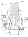
- Figure 1 shows a sectional view of the transfer device (8) by gravity of powder or granules in the closed position according to a first embodiment.
- This device is inserted between the container upper (1) of generally cylindrical shape.
- This upper container is provided a drain opening (1 ').
- the lower container (2) of general shape with vertical axial symmetry is provided with a filling opening (2 ').
- the fixing plate (10) is secured to the lower container (2). He is by example removably secured to a flange (101) itself secured to the opening (2 ') of the lower container (2).
- the plate (10) is arranged flush with the opening of the lower container (2).
- the plate (10) is provided with a passage (110, fig2) with a diameter at least one fifth smaller the diameter of the opening (2 ') of the lower container.
- the plate (10) has a rib circular (105) in which is placed an O-ring (105 ') located in outer periphery of the wall of the lower container (2).
- the tray (10) comprises a part with vertical axial symmetry generally cylindrical (101) which delimits the passage outside (110).
- the part (101) is itself provided with an annular rib (106) in which is disposed an O-ring seal (106 ').
- the rib is arranged slightly inside the passage (110) on the lateral surface of the part (101) facing the contact surface of the shutter (30) of so as to make contact between the O-ring (106 ') and the shutter (30).
- the shutter rod On its upper end (31a), the shutter rod is secured to a metal structure (32, fig 4), for example a star.
- the metallic structure (32) is itself secured to the internal walls of the element (20) and also makes the shutter (30) integral with the displacements of the element (20).
- the shutter (30) has a shape in the direction of the passage general of spherical or frustoconical cap to promote flow. The maximum diameter of the spherical cap is very slightly greater than that of the passage (110) in the plate (10).
- the general structure is suitable for support the weight of the granules and powders contained in the element.
- a dome (80) in the shape of a spherical cap or cone is arranged in the center and on top of the metal structure (32) and covers part of the metallic structure (32). The function of this dome is to prevent any accumulation of powders or granules which can clump together on the metallic structure (32) in order to avoid a retention zone.
- the slice upwardly oriented metal profiles (32) also have a bias or a shape avoiding the retention of matter in balance on the edge.
- FIG. 10 On the plate (10) are arranged three jacks for example identical pneumatic or electric or hydraulic displacement vertical (51, 151, 251) arranged on a circle whose center passes through the axis of symmetry of the element (20) and each arranged at 120 ° from one another.
- This arrangement is visible in Figure 4.
- Figure 1 appears only the cylinder (51).
- the jack (51) is secured to a frame (52) which is itself secured to the tray (10).
- the frame (52) is adjustable in height and makes it possible to adjust the height of the jack (51) relative to the plate (10).
- the rod (56) of the jack (51) is arranged vertically.
- a support plate (55) is made integral with the displacements of the rod (56) of the jack.
- the first ends (53a, 53'a (fig 4)) arms (53, 53 '(fig4)) are secured to this support plate (55).
- the support plate (55) has two orifices (58a, 58b) with axial symmetry vertical.
- Two guide rods (54a, 54b) with vertical axial symmetry and secured to the plate (10) pass through the orifices (58a, 58b).
- figure 1 only appears the guide rod (54a) and the arm (53), the second of which end (53b) is integral with the element (20).
- the function of these rods guidance is to consolidate the entire system linked to the cylinder due to mechanical stresses and so that the displacement of the rods of the cylinder and element are vertical.
- the arms (53, 53 ') form a identical angle of approximately 45 ° with the vertical. According to their other ends (53b, 53'b), the arms (53, 53 ') are secured to an element (20).
- Each cylinder is controlled by hydraulic fluid and the user can therefore check, by this means, the relative position of the ends (53b, 53'b) of the arm (53b, 53'b) relative to the plate and thus the position of the element (20).
- Each cylinder (51, 151, 251) drives the arms in vertical translation respective (53, 53 ', 153, 153', 253, 253 ') and therefore actually translates vertical the element (20).
- the element (20) has a vertical axial symmetry. On his part low, it has a cylindrical surface (20c), on its middle part, it has a frustoconical surface (20b), on its upper part, it has a cylindrical surface (20a).
- the diameter of the cylinder corresponding to the surface (20c) is less than the diameter of the container emptying opening (2 ') lower (2).
- the diameter of the cylinder corresponding to the surface (20a) is greater than the diameter of the filling opening (1 ') of the container upper (1).
- a flange (41) of diameter adaptable to the diameter of the outer wall (1a) of the container (1) On the upper part (20a) of the element is fixed a flange (41) of diameter adaptable to the diameter of the outer wall (1a) of the container (1).
- the function of this washer is to provide a seal, so that that the granules remain confined in the element (20) and cannot escape on its upper part.
- the function of this washer is to provide a seal so that the granules cannot escape in height, above the wall (110) of the plate (10).
- the plate (10) are also arranged at 120 ° from each other others, three identical springs with vertical linear displacement (61, 161, 261) arranged on a circle whose center passes through the axis of symmetry of the element (20).
- This arrangement is visible in schematic figure 4.
- the spring (61) On the Figure 1 appears the spring (61).
- the axis of the spring (61) is in the plane of the cylinder axis (51) and on the other side of the vertical axis of symmetry of the element (20).
- a horizontal arm (62) linked to the spring (61) also comes support the element (20).
- This arm (62) is supported in its middle by the spring (61).
- This spring (61) with a vertical axis is secured to the plate (10).
- the spring (61) is provided with means for adjusting its return force.
- a function of arm-spring couples (62, 61) (162, 161) (262, 261) is to support the element (20) and to ensure the flow stops when the cylinders (51, 151, 251) are not supplied and do not stress the element down.
- a vibrating device On the arm (62) is mounted a vibrating device (63).
- the function of this device (63) is to vibrate the element (20) in order to peel off the pulverulent or granules which could attach to the wall or on the structure (32).
- a metal structure (32) inside the element (20), facing for example arms (62, 162, 262) is arranged and secured to the internal walls of the element (20) a metal structure (32).
- the structure metallic (32) has a star shape with three branches whose center passes through the axis of symmetry of the element (20).
- Metal structure (32) is for example joined by welding or by any other means to the upper end (31a) of the shutter rod (31).
- FIG. 4 appears, top view, a schematic figure of means for translating and supporting the element, i.e. systems related to cylinders and springs.
- the cylinder-spring pairs (51.61 (151,161) (251,261) are each arranged in three planes which contain each axis of symmetry of the element, the axis of the spring and the axis of the rod of the cylinder, the cylinder axis and the spring axis being arranged on either side of the vertical axis of symmetry of the element. These three planes form two by two angles of 120 °.
- the structures linked to the cylinders (51, 52, 53, 53 ', 55, 54a, 54b, 56, 58a, 58b) and (151, 152, 153, 153 ', 155, 154a, 154b, 156, 158a, 158b) and (251, 252, 253, 253 ', 255, 254a, 254b, 256, 258a, 258b) are identical in their form and in their realization.
- the cylinders In the closed position, the cylinders are not supplied and the element is biased upwards by the springs (61, 161, 261) and as shown in Figure 1, the shutter (30) is supported on the plate (10) and in particular on the seal (106 ').
- the user supplies the cylinders (51, 151, 251), which has the effect of lowering the ends (53a, 53'a, 153a, 153'a, 253a, 253'a) arms (53, 53 ', 153, 153', 253, 253 ') and therefore results in downward vertical translation of the entire structure secured to the element (20) also ensuring vertical translation descending from the shutter (30).
- the device according to the invention therefore makes it possible to obtain a device adjustable gravity transfer of powder or granules.
- Figure 5 shows a sectional view of the transfer device by gravity of powder or granules in the closed position according to a second embodiment.
- the element (20.2) has the characteristics described below allowing in particular to maximize the gravity transfer rate of powder or granules in the open position.
- the element (20) is rigid and in its lower part (20c) it leads by a constriction of the lower part (20c) in a piece of pipe (101) integral with the plate (10).
- the lower part (20c.2) of the element (20.2) is flexible and surrounds the passage (110) made in the plate (10).
- the lower part (20c.2) of the element (20.2) has a cylindrical shape with a diameter equal to passage diameter (110).
- This lower part (20c.2) consists of a flexible material such as plastic, canvas or rubber. according to its lower end, the lower part (20c.2) of the element (20.2) is secured to the plate (10) and delimits the passage (110). As shown in Figure 5, it can for example be secured between two plates (10a, 10b) superimposed and joined together which constitute the plate (10). According to its upper end, the lower part (20c.2) of the element (20.2) is secured to the lower end of the upper part (20a.2) of the element (20).
- the upper part (20a.2) of the element (20) has a shape cylindrical with a diameter equal to that of the passage (110). It is rigid, made for example of metal, and surrounds the drain opening (1 ') of the upper container (1).
- the upper part (20a.2) of the element (20) is integral with a plate (210) consisting of two plates (210a, 210b) superimposed and joined together.
- the tray (210) has a ring shape circular whose inside diameter is equal to that of the outside diameter of the upper part (20a.2) of the element (20.2) and whose outer radius is less than the distance between the cylinders (51,151,251) from the axis of symmetry of the element (20).
- the function of the tray (210) is to serve as a support for connection between the upper part (20a.2) of the element (20.2) and the means of support (53, 53 ', 153, 153', 253, 253 ') and elastic means (61161261).
- Figure 6 shows the gravity transfer device of pulverulent or granules in the open position according to the second mode of production.
- the user supplies the cylinders (51,151,251) which has the effect of lowering the same arms height (53, 53 ', 153, 153', 253, 253 ') and therefore lead to vertical downward translation of the entire structure secured to the funnel (20.2) ensuring the vertical descent of the shutter (30) and therefore freeing up a space between the passage (110) and the shutter (30) by which the granules can pass into the lower container (2).
- the lower part (20c.2) of the element (20.2) which is flexible collapses and bulges under the pressure of the granules.
- the granules fall through a useful section variable which is equal to that of the diameter of the passage (110) minus that of the shutter rod (31) at the passage.
- the descent of the shutter (30) is only limited by the stroke of the jacks while in the first embodiment, the flow rate was limited by the narrowing of the lower part (20C) of the element (20).
- the second embodiment therefore has the advantage over the first embodiment of be able to increase the maximum flow rate of granules in the open position.
- Figure 7 shows the gravity transfer device of powder or granules in the reduced opening position.
- the user supplies the cylinders (51,151,251) less which has the effect of reducing the distance separating the shutter (30) from the passage (110) and therefore to decrease the flow rate of granules.
- the lower part (20a.2) flexible of the element (20) then has a general shape cylindrical but slightly curved under the pressure of granules.
- FIGS. 8A to 8D A third embodiment will now be described in reference to FIGS. 8A to 8D.
- the lower part (91) of the element (20) of the transfer device is flexible in accordance with second embodiment described above with reference to the figures 5 to 7.
- the difference between the third embodiment and the first or the second embodiment resides in the structure and the functioning closing means (930, 931) and in the arrangement of the part (91) upper container (2) lower.
- the lower part (91, fig.8A) of the element (20) therefore comprises a cylinder of flexible material mounted on the ends of elastic means (not shown) in accordance with the elastic means (61 in FIG. 5).
- the means (930, 931) for closing are made up of two complementary parts.
- the first part (930) is mounted in the lower part (91) of the element (20) and the second part (931) is mounted in an intermediate element (92) mounted on the part upper container (2) lower.
- the first part (930) of the means opening is fixed to the lower part of the element (20) in accordance with first two embodiments described above.
- the elastic means ensure the contact between the lower part (91) and the first part (930) of the means of closure to maintain the sealing of the element (20).
- the plate (10) as described with reference to Figure 1 is fixed on the upper end of the lower container (2).
- the plate (10) allows the assembly of the intermediate element (92).
- This intermediate element (92) ensures in particular the guidance of the flow of pulverulent material towards the lower container (2) and the tightness of the connection between the container upper and lower container (2).
- the element (92) intermediate includes, for example, a cylindrical envelope made in a flexible material. This material is substantially of the same nature as the material constituting the lower part (91) of the element (20).
- the diameter of the cylindrical casing (92) is substantially the same as the diameter of the lower part (91) of the element (20).
- the lower end (920) of the intermediate casing (92) is integral with the plate (10) while the upper end (921) of the envelope (92) is secured to a plate (94) intermediate.
- the intermediate plate (94) is mounted on the plate (10) by means of at least one jack (95) or means for setting in place equivalent translations.
- the intermediate casing (92) is produced in two parts (921, 922), by example, roughly the same height.
- the two parts are assembled on the one hand to a ring (924) fixed to the plate (94) intermediate by via a square (941) and on the other hand, either on the plate (94) intermediate for the upper part (923) of the envelope (92) intermediate, or to the plate (10) for the lower part (922) of the intermediate envelope (92). So the deformations of the lower part (922) of the intermediate envelope (92) is linked to the relative movements of the lower plate (10) relative to the intermediate plate (94).
- the second part (931) of opening means is mounted in the intermediate element (92).
- the second part (931) of the opening means comprises, according to its longitudinal axis, a tube (932) fixed to the plate by means of at least a fixing lug (97) forming for example a cross system.
- the second part (931) of the opening means is fixed in translation relative to the lower container (2).
- the faces (933, 934) facing the two parts (931, 932) of the opening means are of complementary shapes and chosen so that the two parts (931, 932) of the opening means can, by example, fitting into each other.
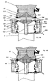
- FIG. 8A represents the device according to the third mode of realization in a so-called prepositioning position.
- the lower part (91) of the element (20) is in contact with the first part (930) opening means for sealing the container superior.
- the upper end (921) of the intermediate casing (92) is in contact with the second part (931) of the opening means for seal the lower container (2).
- the faces (933, 934) facing each other of the two parts (931, 932) of the opening means are distant one the other. In this position, the watertightness of one of the containers is ensured regardless of that of the other container. So the risk of contamination becomes non-existent and allows a dust-free connection.
- This cleaning system aims to get rid of any product contaminating the contact surface between the two parts (931, 930) of the opening means.
- This system includes, for example, means (960) for injecting air. These injection means (960) air are connected to the tube (932) ensuring the mounting of the second part (931) of the opening means.
- the second part (931) of the means opening then comprises, for example, along its longitudinal axis and in opposite the end of the tube (932) a channel (962) which opens out from the face (934) facing the face (933) of the first part (930) of the means opening.
- the system cleaning may also include suction means (961) of air arranged on the plate (94) and intended to suck in the air located between the two parts (930, 931) of the opening means. So by action simultaneous or not, means (962) for injecting air and means (961) air intake, the space delimited by the faces (933, 934) opposite the two parts (931, 932) of the opening means is rid of impurities likely to contaminate the pulverulent material transported.
- suction means (961) of air arranged on the plate (94) and intended to suck in the air located between the two parts (930, 931) of the opening means. So by action simultaneous or not, means (962) for injecting air and means (961) air intake, the space delimited by the faces (933, 934) opposite the two parts (931, 932) of the opening means is rid of impurities likely to contaminate the pulverulent material transported.
- FIG. 8B represents the device according to the third mode of realization in a so-called assembled position.
- the circulation of the pulverulent material between the upper container and the lower container is always prohibited by contact between the first (930), respectively second (931) part of the opening means and the element (935), respectively the element (92) intermediate.
- the faces (933, 934) facing the two parts (931, 932) of the opening means are brought into contact, for example a movement relative of one of the two elements (20) or (94). Therefore, the first and second parts (930, 931) of the opening means are fitted one in the other and thus trap any residual impurities.
- the tightness of the assembly of the two parts (930, 931) of the means opening is, for example, ensured by a seal (920) placed on the perimeter of one of the parts (930, 931) of the opening means.
- this joint (920) engages in a groove (935) produced in the other part of the opening means.
- the end bottom of the lower part (91) of the element (20) is also in contact watertight with the upper end (921) of the intermediate casing (92).
- the latter include a peripheral groove and suction means (960, 932, 962) allowing a relative vacuum to be produced.
- FIG. 8C represents the device according to the third mode of realization in a so-called open position. This position is obtained by actuation of the cylinders (95). The movement of the jacks (95) acts to move the contact area between the lower end of the part (91) bottom of the element (20) and the upper end (921) of the casing (92) intermediate with respect to the two parts (930, 931) assembled means of opening. According to the third embodiment shown in the FIG. 8C, the displacement of the contact zone is carried out so that this is located above the first part (930) of the means opening. Thus, a space is freed between the opening means and the intermediate casing (92) to allow the material to flow powder. Under the effect of the flow pressure, the envelope (92) intermediate bulges to facilitate flow.
- FIG. 8D represents the device according to the third mode of realization in a so-called reduced opening position.
- the difference with the position shown in Figure 8C is that in the position shown in the FIG. 8D, the space freed up between the opening means and the envelope (92) intermediate is decreased by the movement of the cylinders (95) in the direction of back to the assembled position, in which the lower part (922) of the envelope forms folds.
- the invention therefore relates to an adjustable transfer device by gravity of powder or granules between an upper container (1) provided at least one drain opening (1 ') opening downwards and a lower container (2) provided with at least one filling opening (2 ') opening upwards, characterized in that it comprises an element (20, 20.2) of pipe, the upper part (20a, 20a.2) of which surrounds the opening of emptying (1 ') of the upper container, the lower part (20c, 20c.2, 91) of the element (20, 20.2) being connected to a plate (10) fixed flush with the opening filling (2 ') of the lower container (2), this plate (10) being provided a passage (110) located above the opening (2 ') of the container (2) lower, and in that the element (20, 20.2) is at least partially translatable by means of translational means which allow the passage (110) to be closed or freed in an adjustable manner thanks to at least closing and opening means (30, 930, 931) partially integral with the element (20, 20.2), to allow flow powders or granules.
- the lower part (20c) of the element (20) opens into a pipe part (101) integral with the plate (10), the pipe part (101) surrounding the passage (110).
- the lower part (20c.2) of the element (20.2) is flexible and secured to the plate (10), and the lower part (20c.2) of the element (20.2) surrounds the passage (110).
- the passage (110) located above of the opening (2 ') of the lower container (2) is of a diameter less than the opening (2 ') of the lower container (2).
- the means (30) for closing and are a shutter.
- the shutter (30) is in the form of spherical cap.
- the shutter (30) is secured to a shutter rod (31) along one of the ends (31b) of the rod shutter (31), at its other end (31a) the shutter rod (31) is secured to a metal structure (32) itself secured to the walls internal elements (20, 20.2).
- a dome (80) surrounds the axis vertical symmetry of the element (20, 20.2) and covers part of the metallic structure (32).
- the element (20, 20.2) and the closing and opening means (30) integral with the element (20, 20.2) are actuated in translation by means (51, 151, 251) for setting translation arranged outside the element but integral with the element by support means (53, 53 ', 153, 153', 253, 253 ').
- the means for setting translation (51, 151, 251) comprise at least one cylinder.
- the support means (53, 53 ', 153, 153', 253, 253 ') include at least one arm, one end of which (53a, 53'a, 153a, 153'a, 253a, 253'a) is actuated in translation by a support (55, 155, 255) fixed on the rod (56, 156, 256) of each cylinder and of which the other end (53b, 53'b, 153b, 153'b, 253b, 253'b) is secured to the element (20, 20.2).
- the element (20) is supported by elastic means (61, 161, 261) disposed between the plate (10) and suspension arms (62, 162, 262).
- the element (20.2) is supported by elastic means (61, 161, 261) disposed between the plate (10) and a plate (210) secured to the upper part (20a.2) of the element (20.2).
- the element (20, 20.2) is rendered integral with vibrating means (63, 163, 263).
- the means for vibrating (63, 163, 263) of the element (20) are secured to the arms (62, 162, 262) supported by elastic means (61, 161, 261).
- the means for vibrating (63, 163, 263) of the element (20.2) are secured to the plate (210) secured to the upper part (20a.2) of the element (20.2).
- the axis of the rod (56) of the jack (51), the axis of the spring (61) and the axis of symmetry of the element (20, 20.2) are parallel and contained in the same plane
- the jack (51) and the spring (61) are arranged on either side of the axis of symmetry of the element (20, 20.2) and in that the axis of the rod (156) of the jack (151), the axis of the spring (161) and the axis of symmetry of the element (20, 20.2) are parallel and contained in a same plane
- the jack (151) and the spring (161) are arranged on both sides of the axis of symmetry of the element (20, 20.2) and in that the axis of the rod (256) of the jack (251), the axis of the spring (261) and the axis of symmetry of the element (20, 20.2) are parallel and contained in the same plane
- the jack (251) and the springs (261) are arranged on either side of the axis of symmetry of
- the adjustable transfer device by gravity of pulverulent or granules comprises sealing means (41) arranged between the element (20, 20.2) and the upper container (1).
- the adjustable transfer device by gravity of pulverulent or granules comprises sealing means (42) arranged between the pipe part (101) of the plate (10) and the element (20).
- the opening means are in two parts (930, 931), a first part (930) is integral with the part bottom (91) of the element (20) to ensure in one position, the tightness of the upper container and the second part (931) is mounted in an element (92) intermediate to seal the lower container, the element (92) intermediate being mounted between the lower part of the element (20) and the plate (10).
- the intermediate element (92) is made of flexible material.
- the lower end (924) of the intermediate element (92) is fixed on the plate (10) and the end (921) upper of the intermediate element (92) is fixed on a plate intermediate, the intermediate plate (94) being movable in translation along the vertical axis with respect to the plate (10).
- the intermediate element (92) comprises a first envelope (922) fixed on the one hand to the plate (10) and on the other hand to a rigid ring (924), and a second envelope (923) fixed on the one hand to the intermediate plate (94) and on the other hand to the ring (924) rigid, the ring (924) being secured to the intermediate plate (94) and fixed in position relative to the plate.
- the device comprises means (960, 961) for cleaning the space delimited by the faces (933, 934) facing the two parts (930, 931) constituting the means opening.
- the cleaning means include means (960, 962) for injecting air into the defined space by the faces (933, 934) facing the two parts (930, 931) constituting the opening means, through a channel (962) passing through the part (931) lower opening means.
- the cleaning means comprise air suction means (920) mounted on the plate (94) intermediate to draw air from the space delimited by the faces (933, 934) opposite the two parts (930, 931) constituting the opening means.
- the device comprises a shutter movable between two positions and arranged in a connecting channel between the upper container (1) and the lower container (2).
- the mobile shutter includes a tray (94) connected by a deformable upper sleeve (91) to the container upper and a deformable sleeve (922) connected to the lower container (2), means for actuating the plate between three positions.
- the device comprises a open position in which the shutter is facing a sleeve intermediate (923) of diameter greater than the obturation in at least one position and connecting the upper sleeve to the lower sleeve to allow the flow around the shutter.
- the device comprises a second closed position in which the shutter bears on the upper sleeve (91) and deforms it.
- the device comprises a third cleaning position in which position (94) is most close to the plate (10) secured to the lower container and the separate shutter in two parts (930, 931), one part (930) ensuring with the sleeve (91) upper sealing of the upper container and a part (931) ensuring with the intermediate sleeve (922) the sealing of the lower container (2).
Landscapes
- Engineering & Computer Science (AREA)
- Mechanical Engineering (AREA)
- Filling Or Emptying Of Bunkers, Hoppers, And Tanks (AREA)
- Preparation Of Clay, And Manufacture Of Mixtures Containing Clay Or Cement (AREA)
- Discharge Of Articles From Conveyors (AREA)
Claims (29)
- Einstellbare Vorrichtung zum Transport mittels Schwerkraft von pulverförmigem oder körnigem Material zwischen einem oberen Behälter (1), der mit mindestens einer Entleerungsöffnung (1') versehen ist, die nach unten mündet, und einem unteren Behälter (2), der mit mindestens einer Auffüllöffnung (2') versehen ist, die nach oben mündet, dadurch gekennzeichnet, daß die Vorrichtung ein Kanalisationselement (20, 20.2) aufweist, dessen oberes Teil (20a, 20a.2) die Entleerungsöffnung (1') des oberen Behälters umgibt, wobei das untere Teil (20c, 20c.2, 91) des Elements (20, 20.2) mit einer Platte (10) verbunden ist, die dicht bei der Auffüllöffnung (2') des unteren Behälters (2) befestigt ist, wobei die Platte (10) mit einer Passage (110) versehen ist, die sich oberhalb der Öffnung (2') des unteren Behälters (2) befindet, und daß das Element (20, 20.2) mindestens teilweise in Translationsbewegung betätigbar ist durch Translationsmittel, die es gestatten, die Passage (110) aufgrund von Verschließ- und Öffnungsmitteln (30, 930, 931), die mindestens teilweise mit dem Element (20, 20.2) verbunden sind, einstellbar zu verschließen oder zu öffnen, um den Ablauf des pulverförmigen oder körnigen Materials zu gestatten.
- Einstellbare Vorrichtung zum Transport mit Schwerkraft von pulverförmigem oder körnigem Material gemäß Anspruch 1, dadurch gekennzeichnet, daß das untere Teil (20c) des Elements (20) in ein mit der Platte (10) verbundenes Kanalisationsstück (101) mündet, wobei das Kanalisationsstück (101) die Passage (110) umgibt.
- Einstellbare Vorrichtung zum Transport mittels Schwerkraft von pulverförmigem oder körnigem Material gemäß Anspruch 1, dadurch gekennzeichnet, daß das untere Teil (20c.2) des Elements (20.2) flexibel und mit der Platte (10) verbunden ist, und daß das untere Teil (20c.2) des Elements (20.2) die Passage (110) umgibt.
- Einstellbare Vorrichtung zum Transport mittels Schwerkraft von pulverförmigem oder körnigem Material gemäß Anspruch 2 oder 3, dadurch gekennzeichnet, daß die oberhalb der Öffnung (2') des unteren Behälters (2) sich befindende Passage (110) einen Durchmesser aufweist, der geringer ist als die Öffnung (2') des unteren Behälters (2).
- Einstellbare Vorrichtung zum Transport mittels Schwerkraft von pulverförmigem oder körnigem Material gemäß einem der Ansprüche 1 bis 4, dadurch gekennzeichnet, daß die Schließ- und Öffnungsmittel (30) ein Obturateur ist.
- Einstellbare Vorrichtung zum Transport mit Schwerkraft von pulverförmigem oder körnigem Material gemäß Anspruch 5, dadurch gekennzeichnet, daß der Obturateur (30) in Form einer kugelförmigen Kappe vorliegt.
- Vorrichtung zum Transport mittels Schwerkraft von pulverförmigem oder körnigem Material gemäß Anspruch 5 oder 6, dadurch gekennzeichnet, daß der Obturateur (30) mit einer Obturateur-Stange (31) verbunden ist, nämlich über ein Ende (31b) der Obturateur-Stange (31), wobei die Obturateur-Stange (31) über ihr anderes Ende (31a) mit einem metallischen Strukturteil (32) verbunden ist, welches seinerseits mit inneren Wänden des Elements (20, 20.2) verbunden ist.
- Vorrichtung zum Transport mittels Schwerkraft von pulverförmigem oder körnigem Material gemäß Anspruch 7, dadurch gekennzeichnet, daß eine Kuppel (80) die vertikale Symmetrieachse des Elements (20, 20.2) umgibt und einen Teil des metallischen Strukturteils (32) bedeckt.
- Einstellbare Vorrichtung zum Transport mittels Schwerkraft von pulverförmigem oder körnigem Material gemäß einem der Ansprüche 1 bis 8, dadurch gekennzeichnet, daß das Element (20, 20.2) und die mit dem Element (20, 20.2) verbundenen Öffnungs- und Schließmittel (30) in Translationsbewegung versetzt werden mittels Translationsmitteln (51, 151, 251), die am Element außen, aber mit dem Element mittels Stützausbaumitteln (53, 53', 153, 153', 253, 253') verbunden angeordnet sind.
- Einstellbare Vorrichtung zum Transport mittels Schwerkraft von pulverförmigem oder körnigem Material gemäß Anspruch 9, dadurch gekennzeichnet, daß die Translationsbewegungsmittel (51, 151, 251) mindestens ein Stellglied aufweisen.
- Einstellbare Vorrichtung zum Transport mittels Schwerkraft von pulverförmigem oder körnigem Material gemäß Anspruch 10, dadurch gekennzeichnet, daß die Stützausbaumittel (53, 53', 153, 153', 253, 253') mindestens ein Rohr aufweist, dessen eines Ende (53a, 53'a, 153a, 153'a, 253a, 253'a) durch einen Träger (55, 155, 255) in Translationsbewegung versetzt wird, der an der Stange (56, 156, 256) von jedem Stellglied befestigt ist, und dessen anderes Ende (53b, 53'b, 153b, 153'b, 253b, 253'b) mit dem Element (20, 20.2) verbunden ist.
- Einstellbare Vorrichtung zum Transport mittels Schwerkraft von pulverförmigem oder körnigem Material gemäß einem der Ansprüche 2 oder 4 bis 11, falls von Anspruch 2 abhängig, dadurch gekennzeichnet, daß das Element (20) durch elastische Mittel (61, 161, 261) abgestützt wird, die zwischen der Platte (10) und Verteilerarmen (62, 162, 262) angeordnet sind.
- Einstellbare Vorrichtung zum Transport mittels Schwerkraft von pulverförmigem oder körnigem Material gemäß einem der Ansprüche 3 bis 11, falls abhängig vom Anspruch 3, dadurch gekennzeichnet, daß das Element (20.2) durch elastische Mittel (61, 161, 261) abgestützt wird, die zwischen der Platte (10) und einer Platte (210) angeordnet sind, die mit dem oberen Teil (20a.2) des Elements (20.2) verbunden ist.
- Einstellbare Vorrichtung zum Transport mittels Schwerkraft von pulverförmigem oder körnigem Material gemäß Anspruch 12 oder 13, dadurch gekennzeichnet, daß das Element (20, 20.2) durch Schwingungsmittel (63, 163, 263) verbunden wird.
- Vorrichtung zum Transport mittels Schwerkraft von pulverförmigem oder körnigem Material gemäß Anspruch 13, dadurch gekennzeichnet, daß die Schwingungsmittel (63, 163, 263) des Elements (20) mit den durch die elastischen Mittel (61, 161, 261) gestützten Armen (62, 162, 262) verbunden sind.
- Vorrichtung zum Transport mittels Schwerkraft von pulverförmigem oder körnigem Material gemäß Anspruch 13, dadurch gekennzeichnet, daß die Schwingungsmittel (63, 163, 263) des Elements (20.2) mit der Platte (210) verbunden sind, die mit dem oberen Teil (20a.2) des Elements (20.2) verbunden ist.
- Vorrichtung zum Transport mittels Schwerkraft von pulverförmigem oder körnigem Material gemäß Anspruch 11, dadurch gekennzeichnet, daß die Achse der ersten Stange (56) des ersten Stellglieds (51), die Achse der ersten Feder (61) und die Symmetrieachse des Elements (20, 20.2) parallel sind und in einer gleichen ersten Ebene verlaufen, wobei das erste Stellglied (51) und die erste Feder (61) zu beiden Seiten der Symmetrieachse des Elements (20, 20.2) angeordnet sind, und daß die Achse der zweiten Stange (156) des zweiten Stellglieds (151), die Achse der zweiten Feder (161) und die Symmetrieachse des Elements (20, 20.2) parallel sind und in einer gleichen zweiten Ebene verlaufen, wobei das zweite Stellglied (151) und die zweite Feder (161) zu beiden Seiten der Symmetrieachse des Elements (20, 20.2) angeordnet sind, und daß die Achse der dritten Stange (256) des dritten Stellglieds (251), die Achse der dritten Feder (261) und die Symmetrieachse des Elements (20, 20.2) parallel sind und in einer gleichen dritten Ebene verlaufen, wobei das dritte Stellglied (251) und die dritte Feder (261) zu beiden Seiten der Symmetrieachse des Elements (20, 20.2) angeordnet sind, und daß diese ersten, zweiten und dritten Ebenen jeweils zwei zueinander einen Winkel von 120° bilden.
- Einstellbare Vorrichtung zum Transport mittels Schwerkraft von pulverförmigem oder körnigem Material gemäß einem der Ansprüche 1 bis 17, dadurch gekennzeichnet, daß sie Dichtungsmittel (41) aufweist, die zwischen dem Element (20, 20.2) und dem oberen Behälter (1) angeordnet sind.
- Einstellbare Vorrichtung zum Transport mittels Schwerkraft von pulverförmigem oder körnigem Material gemäß einem der Ansprüche 2 oder 4 bis 18, falls von Anspruch 2 abhängig, dadurch gekennzeichnet, daß sie Dichtungsmittel (42) umfaßt, die zwischen dem Kanalisationsstück (101) der Platte (10) und dem Element (20) angeordnet sind.
- Einstellbare Vorrichtung zum Transport mittels Schwerkraft von pulverförmigem oder körnigem Material gemäß Anspruch 1, dadurch gekennzeichnet, daß die Öffnungsmittel in Form zweier Teile (930, 931) vorliegen, wobei ein erstes Teil (930) mit dem unteren Teil (91) des Elements (20) verbunden ist, um in einer Position die Abdichtung des oberen Behälters sicherzustellen, und wobei das zweite Teil (931) auf einem Zwischenelement (92) montiert ist, um die Abdichtung des unteren Behälters sicherzustellen, wobei das Zwischenelement (92) zwischen dem unteren Teil des Elements (20) und der Platte (10) montiert ist.
- Einstellbare Vorrichtung zum Transport mittels Schwerkraft von pulverförmigem oder körnigem Material gemäß Anspruch 20, dadurch gekennzeichnet, daß das Zwischenelement (92) aus flexiblem Material gefertigt ist.
- Einstellbare Vorrichtung zum Transport mittels Schwerkraft von pulverförmigem oder körnigem Material gemäß Anspruch 20 oder 21, dadurch gekennzeichnet, daß das untere Ende (922) des Zwischenelements (92) mit der Platte (10) befestigt ist und das obere Ende (921) des Zwischenelements (92) mit einer Zwischenplatte befestigt ist, wobei die Zwischenplatte (94) in Bezug auf die vertikale Achse im Verhältnis zur Platte (10) translatorisch beweglich ist.
- Einstellbare Vorrichtung zum Transport mittels Schwerkraft von pulverförmigem oder körnigem Material gemäß Anspruch 22, dadurch gekennzeichnet, daß das Zwischenelement (92) eine erste Umhüllung (922), die einerseits an der Platte (10) und andererseits an einem festen Ring (924) befestigt ist, und eine zweite Umhüllung (923), die einerseits an der Zwischenplatte (94) und andererseits an dem festen Ring (924) befestigt ist, aufweist, wobei der Ring (924) mit der Zwischenplatte (94) verbunden ist und in seiner Position im Verhältnis zur Platte festgelegt ist.
- Einstellbare Vorrichtung zum Transport mittels Schwerkraft von pulverförmigem oder körnigem Material gemäß einem der Ansprüche 20 bis 23, dadurch gekennzeichnet, daß sie Reinigungsmittel für den Raum aufweisen, der durch die Flächen (933, 934) gegenüber den beiden, die Öffnungsmittel bildenden Teilen (930, 931) begrenzt wird, wobei diese Mittel eine staubfreie Verbindung gestatten.
- Einstellbare Vorrichtung zum Transport mittels Schwerkraft von pulverförmigem oder körnigem Material gemäß Anspruch 24, dadurch gekennzeichnet, daß die Reinigungsmittel Mittel (960, 962) zum Injizieren von Luft, durch einen durch das untere Teil (931) der Öffnungsmittel laufenden Kanal (962), in den Raum aufweist, der durch die Flächen (933, 934) gegenüber den beiden, die Öffnungsmittel bildenden Teilen (930, 931) begrenzt wird.
- Einstellbare Vorrichtung zum Transport mittels Schwerkraft von pulverförmigem oder körnigem Material gemäß Anspruch 24 oder 25, dadurch gekennzeichnet, daß die Reinigungsmittel Mittel (920) zum Ansaugen von Luft, die an der Zwischenplatte (94) montiert sind, aufweisen, um die Luft des Raums abzusaugen, der durch die Seiten (933, 934) gegenüber den beiden, die Öffnungsmittel bildenden Teilen (930, 931) begrenzt wird, wobei diese Mittel eine staubfreie Verbindung gestatten.
- Einstellbare Vorrichtung zum Transport mittels Schwerkraft von pulverförmigem oder körnigem Material gemäß Anspruch 23, dadurch gekennzeichnet, daß sie eine Öffnungsposition aufweist, in der die Öffnungsmittel (930, 931) der zweiten Umhüllung (923) des Zwischenelements (92) gegenüberliegen, mit einem größeren Durchmesser als dem der Öffnungsmittel in mindestens einer Position, um den Ablauf um die Öffnungsmittel herum zu ermöglichen.
- Einstellbare Vorrichtung zum Transport mittels Schwerkraft von pulverförmigem oder körnigem Material gemäß Anspruch 20, dadurch gekennzeichnet, daß sie eine Schließposition aufweist, in der die Öffnungsmittel (930, 931) zum Anschlag auf das untere Teil (91) des Elements (20) kommen und dieses deformieren.
- Einstellbare Vorrichtung zum Transport mittels Schwerkraft von pulverförmigem oder körnigem Material gemäß Anspruch 26, dadurch gekennzeichnet, daß sie eine Reinigungsposition aufweist, in der die Öffnungselemente in Form von zwei Teilen (930, 931), einem oberen und einem unteren, getrennt sind, wobei das obere Teil (930) der Öffnungsmittel mit dem unteren Teil (91) des Elements (20) die Dichtheit des oberen Behälters sicherstellt und das untere Teil (931) der Öffnungsmittel mit der ersten Umhüllung (922) des Zwischenelements (92) die Dichtheit des unteren Behälters (2) sicherstellt.
Applications Claiming Priority (2)
| Application Number | Priority Date | Filing Date | Title |
|---|---|---|---|
| FR0002698 | 2000-03-02 | ||
| FR0002698A FR2805802B1 (fr) | 2000-03-02 | 2000-03-02 | Dispositif reglable de transfert par gravite de pulverulent ou de granules |
Publications (2)
| Publication Number | Publication Date |
|---|---|
| EP1129968A1 EP1129968A1 (de) | 2001-09-05 |
| EP1129968B1 true EP1129968B1 (de) | 2004-11-10 |
Family
ID=8847654
Family Applications (1)
| Application Number | Title | Priority Date | Filing Date |
|---|---|---|---|
| EP01400456A Expired - Lifetime EP1129968B1 (de) | 2000-03-02 | 2001-02-21 | Verstellbare Vorrichtung zur Förderung mittels Schwerkraft von pulverförmigem oder körnigem Material |
Country Status (4)
| Country | Link |
|---|---|
| EP (1) | EP1129968B1 (de) |
| AT (1) | ATE281995T1 (de) |
| DE (1) | DE60106992T2 (de) |
| FR (1) | FR2805802B1 (de) |
Families Citing this family (5)
| Publication number | Priority date | Publication date | Assignee | Title |
|---|---|---|---|---|
| EP1279623B1 (de) * | 2001-07-25 | 2005-06-29 | Ivan Semenenko | Füllverschluss für Behälter |
| WO2010134102A1 (en) * | 2009-05-19 | 2010-11-25 | Abc Pharmatech S.R.L. | Apparatus and method for transferring powdered products |
| EP3552999B1 (de) | 2018-04-13 | 2022-03-23 | Imertech Sas | Ladevorrichtung für partikuläres material |
| CN111776498B (zh) * | 2020-08-03 | 2022-02-08 | 滁州市祥峰建材有限公司 | 一种下料防溅的水泥罐放料装置 |
| CN112221546B (zh) * | 2020-08-27 | 2021-11-26 | 中国科学院苏州生物医学工程技术研究所 | 一种样品转移装置、转移系统及方法 |
Family Cites Families (5)
| Publication number | Priority date | Publication date | Assignee | Title |
|---|---|---|---|---|
| GB472503A (en) * | 1936-05-08 | 1937-09-24 | Jaeger Truck Mixers England Lt | Improvements relating to gates or valves for hoppers and the like |
| GB1505878A (en) * | 1975-09-18 | 1978-03-30 | Simon Solitec Ltd | Transportable container for solid particulate materials |
| GB1594820A (en) * | 1976-12-20 | 1981-08-05 | Mittelmann Gmbh & Co Kg | Sealable container for a flowablematerial |
| GB9303928D0 (en) * | 1993-02-26 | 1993-04-14 | Material Control Eng Ltd | Apparatus for discharging flowable material |
| GB2333287B (en) * | 1999-03-24 | 2002-08-21 | Ivan Semenenko | Material handling apparatus |
-
2000
- 2000-03-02 FR FR0002698A patent/FR2805802B1/fr not_active Expired - Fee Related
-
2001
- 2001-02-21 DE DE60106992T patent/DE60106992T2/de not_active Expired - Fee Related
- 2001-02-21 EP EP01400456A patent/EP1129968B1/de not_active Expired - Lifetime
- 2001-02-21 AT AT01400456T patent/ATE281995T1/de not_active IP Right Cessation
Also Published As
| Publication number | Publication date |
|---|---|
| FR2805802B1 (fr) | 2002-06-07 |
| FR2805802A1 (fr) | 2001-09-07 |
| DE60106992T2 (de) | 2005-11-10 |
| DE60106992D1 (de) | 2004-12-16 |
| EP1129968A1 (de) | 2001-09-05 |
| ATE281995T1 (de) | 2004-11-15 |
Similar Documents
| Publication | Publication Date | Title |
|---|---|---|
| EP2969902B1 (de) | Empfang, entwässerung und übertragung einer grossen menge einer biopharmazeutischen flüssigkeit unter druck zur weiterbehandlung | |
| EP3268291B1 (de) | Vorrichtung zum fördern eines beutels mit einem biopharmazeutischen fluid und systeme und verfahren mit verwendung davon | |
| LU87467A1 (fr) | Dispositif d'obturation de conduites de transport de produits en vrac | |
| EP2001788B1 (de) | Reinigungsvorrichtung für eine füllmaschine | |
| EP1241995A1 (de) | Vorrichtung und anordnung zur stabilisierung der wirbelsäule | |
| EP2121503A1 (de) | Füllmaschine mit reinigungsvorrichtung mit verformbarer membran | |
| EP2121504B1 (de) | Füllmaschine mit reinigungsvorrichtung | |
| EP1129968B1 (de) | Verstellbare Vorrichtung zur Förderung mittels Schwerkraft von pulverförmigem oder körnigem Material | |
| FR2562525A1 (fr) | Manche de chargement a filtration integree | |
| WO2001042086A1 (fr) | Procede et dispositif pour conditionner un solide dans un recipient, tel qu'un flacon | |
| FR2682293A1 (fr) | Lit medical fluidise muni d'un dispositif d'evacuation de ses constituants granulaires souilles. | |
| EP4136379B1 (de) | Behälterbehandlungsanlage | |
| FR2997685A3 (fr) | Dispositif de decharge | |
| FR2732081A1 (fr) | Verin support de structures lourdes et fragiles, tel un miroir de telescope | |
| EP1702871A1 (de) | Flexibler Behälter mit Einbauleitelement | |
| FR2543458A1 (fr) | Procede et installation pour nettoyer des machines de remplissage de bouteilles | |
| EP0453339B1 (de) | Vorrichtung zum Entnehmen von Gas aus einem Tankbehälter | |
| FR2639405A1 (fr) | Dispositif de prelevement de liquide dans une capacite et en particulier dispositif de puisage de carburant dans le reservoir d'un vehicule automobile | |
| FR2881122A1 (fr) | Dispositif de distribution de matieres en vrac | |
| FR2469594A1 (fr) | Dispositif formant outil extensible sous l'effet d'un fluide sous pression | |
| FR3022535A1 (fr) | Dispositif pour le transbordement par aspiration | |
| CH590768A5 (en) | Tank for transporting two different bulk products - has chambers separated by central flexible membrane extending into some or all of tank capacity | |
| WO2020099543A1 (fr) | Dispositif de tireuse pour machine de remplissage et machine comportant de tels dispositifs | |
| FR2751311A1 (fr) | Dispositif de secouage de conteneur rigide et procede de vidage | |
| FR2521252A1 (fr) | Dispositif formant ventouse automatique a grand debit |
Legal Events
| Date | Code | Title | Description |
|---|---|---|---|
| PUAI | Public reference made under article 153(3) epc to a published international application that has entered the european phase |
Free format text: ORIGINAL CODE: 0009012 |
|
| AK | Designated contracting states |
Kind code of ref document: A1 Designated state(s): AT BE CH CY DE DK ES FI FR GB GR IE IT LI LU MC NL PT SE TR |
|
| AX | Request for extension of the european patent |
Free format text: AL;LT;LV;MK;RO;SI |
|
| 17P | Request for examination filed |
Effective date: 20020124 |
|
| AKX | Designation fees paid |
Free format text: AT BE CH CY DE DK ES FI FR GB GR IE IT LI LU MC NL PT SE TR |
|
| 17Q | First examination report despatched |
Effective date: 20030516 |
|
| GRAP | Despatch of communication of intention to grant a patent |
Free format text: ORIGINAL CODE: EPIDOSNIGR1 |
|
| RIN1 | Information on inventor provided before grant (corrected) |
Inventor name: ROBERT, ALAIN |
|
| GRAS | Grant fee paid |
Free format text: ORIGINAL CODE: EPIDOSNIGR3 |
|
| RAP1 | Party data changed (applicant data changed or rights of an application transferred) |
Owner name: BSIPM-BSI PROCESS MANUFACTURING |
|
| GRAA | (expected) grant |
Free format text: ORIGINAL CODE: 0009210 |
|
| AK | Designated contracting states |
Kind code of ref document: B1 Designated state(s): AT BE CH CY DE DK ES FI FR GB GR IE IT LI LU MC NL PT SE TR |
|
| PG25 | Lapsed in a contracting state [announced via postgrant information from national office to epo] |
Ref country code: IT Free format text: LAPSE BECAUSE OF FAILURE TO SUBMIT A TRANSLATION OF THE DESCRIPTION OR TO PAY THE FEE WITHIN THE PRESCRIBED TIME-LIMIT;WARNING: LAPSES OF ITALIAN PATENTS WITH EFFECTIVE DATE BEFORE 2007 MAY HAVE OCCURRED AT ANY TIME BEFORE 2007. THE CORRECT EFFECTIVE DATE MAY BE DIFFERENT FROM THE ONE RECORDED. Effective date: 20041110 Ref country code: AT Free format text: LAPSE BECAUSE OF FAILURE TO SUBMIT A TRANSLATION OF THE DESCRIPTION OR TO PAY THE FEE WITHIN THE PRESCRIBED TIME-LIMIT Effective date: 20041110 Ref country code: TR Free format text: LAPSE BECAUSE OF FAILURE TO SUBMIT A TRANSLATION OF THE DESCRIPTION OR TO PAY THE FEE WITHIN THE PRESCRIBED TIME-LIMIT Effective date: 20041110 Ref country code: NL Free format text: LAPSE BECAUSE OF FAILURE TO SUBMIT A TRANSLATION OF THE DESCRIPTION OR TO PAY THE FEE WITHIN THE PRESCRIBED TIME-LIMIT Effective date: 20041110 Ref country code: FI Free format text: LAPSE BECAUSE OF FAILURE TO SUBMIT A TRANSLATION OF THE DESCRIPTION OR TO PAY THE FEE WITHIN THE PRESCRIBED TIME-LIMIT Effective date: 20041110 |
|
| REG | Reference to a national code |
Ref country code: GB Ref legal event code: FG4D Free format text: NOT ENGLISH |
|
| REG | Reference to a national code |
Ref country code: CH Ref legal event code: EP |
|
| REG | Reference to a national code |
Ref country code: IE Ref legal event code: FG4D Free format text: FRENCH |
|
| REF | Corresponds to: |
Ref document number: 60106992 Country of ref document: DE Date of ref document: 20041216 Kind code of ref document: P |
|
| PG25 | Lapsed in a contracting state [announced via postgrant information from national office to epo] |
Ref country code: SE Free format text: LAPSE BECAUSE OF FAILURE TO SUBMIT A TRANSLATION OF THE DESCRIPTION OR TO PAY THE FEE WITHIN THE PRESCRIBED TIME-LIMIT Effective date: 20050210 Ref country code: DK Free format text: LAPSE BECAUSE OF FAILURE TO SUBMIT A TRANSLATION OF THE DESCRIPTION OR TO PAY THE FEE WITHIN THE PRESCRIBED TIME-LIMIT Effective date: 20050210 Ref country code: GR Free format text: LAPSE BECAUSE OF FAILURE TO SUBMIT A TRANSLATION OF THE DESCRIPTION OR TO PAY THE FEE WITHIN THE PRESCRIBED TIME-LIMIT Effective date: 20050210 |
|
| PG25 | Lapsed in a contracting state [announced via postgrant information from national office to epo] |
Ref country code: LU Free format text: LAPSE BECAUSE OF NON-PAYMENT OF DUE FEES Effective date: 20050221 Ref country code: CY Free format text: LAPSE BECAUSE OF FAILURE TO SUBMIT A TRANSLATION OF THE DESCRIPTION OR TO PAY THE FEE WITHIN THE PRESCRIBED TIME-LIMIT Effective date: 20050221 Ref country code: ES Free format text: LAPSE BECAUSE OF FAILURE TO SUBMIT A TRANSLATION OF THE DESCRIPTION OR TO PAY THE FEE WITHIN THE PRESCRIBED TIME-LIMIT Effective date: 20050221 |
|
| PG25 | Lapsed in a contracting state [announced via postgrant information from national office to epo] |
Ref country code: MC Free format text: LAPSE BECAUSE OF NON-PAYMENT OF DUE FEES Effective date: 20050228 |
|
| REG | Reference to a national code |
Ref country code: CH Ref legal event code: NV Representative=s name: R. A. EGLI & CO. PATENTANWAELTE |
|
| GBT | Gb: translation of ep patent filed (gb section 77(6)(a)/1977) |
Effective date: 20050329 |
|
| NLV1 | Nl: lapsed or annulled due to failure to fulfill the requirements of art. 29p and 29m of the patents act | ||
| PLBE | No opposition filed within time limit |
Free format text: ORIGINAL CODE: 0009261 |
|
| STAA | Information on the status of an ep patent application or granted ep patent |
Free format text: STATUS: NO OPPOSITION FILED WITHIN TIME LIMIT |
|
| 26N | No opposition filed |
Effective date: 20050811 |
|
| PG25 | Lapsed in a contracting state [announced via postgrant information from national office to epo] |
Ref country code: PT Free format text: LAPSE BECAUSE OF NON-PAYMENT OF DUE FEES Effective date: 20050410 |
|
| PGFP | Annual fee paid to national office [announced via postgrant information from national office to epo] |
Ref country code: DE Payment date: 20080229 Year of fee payment: 8 Ref country code: GB Payment date: 20080123 Year of fee payment: 8 Ref country code: IE Payment date: 20080115 Year of fee payment: 8 |
|
| PGFP | Annual fee paid to national office [announced via postgrant information from national office to epo] |
Ref country code: CH Payment date: 20080528 Year of fee payment: 8 Ref country code: FR Payment date: 20080228 Year of fee payment: 8 |
|
| PGFP | Annual fee paid to national office [announced via postgrant information from national office to epo] |
Ref country code: BE Payment date: 20080205 Year of fee payment: 8 |
|
| BERE | Be: lapsed |
Owner name: *BSIPM-BSI PROCESS MFG Effective date: 20090228 |
|
| REG | Reference to a national code |
Ref country code: CH Ref legal event code: PL |
|
| GBPC | Gb: european patent ceased through non-payment of renewal fee |
Effective date: 20090221 |
|
| PG25 | Lapsed in a contracting state [announced via postgrant information from national office to epo] |
Ref country code: CH Free format text: LAPSE BECAUSE OF NON-PAYMENT OF DUE FEES Effective date: 20090228 Ref country code: LI Free format text: LAPSE BECAUSE OF NON-PAYMENT OF DUE FEES Effective date: 20090228 |
|
| REG | Reference to a national code |
Ref country code: IE Ref legal event code: MM4A |
|
| REG | Reference to a national code |
Ref country code: FR Ref legal event code: ST Effective date: 20091030 |
|
| PG25 | Lapsed in a contracting state [announced via postgrant information from national office to epo] |
Ref country code: DE Free format text: LAPSE BECAUSE OF NON-PAYMENT OF DUE FEES Effective date: 20090901 Ref country code: IE Free format text: LAPSE BECAUSE OF NON-PAYMENT OF DUE FEES Effective date: 20090223 |
|
| PG25 | Lapsed in a contracting state [announced via postgrant information from national office to epo] |
Ref country code: BE Free format text: LAPSE BECAUSE OF NON-PAYMENT OF DUE FEES Effective date: 20090228 |
|
| PG25 | Lapsed in a contracting state [announced via postgrant information from national office to epo] |
Ref country code: FR Free format text: LAPSE BECAUSE OF NON-PAYMENT OF DUE FEES Effective date: 20090302 Ref country code: GB Free format text: LAPSE BECAUSE OF NON-PAYMENT OF DUE FEES Effective date: 20090221 |