EP1129975A2 - Dispostif de bobinage - Google Patents
Dispostif de bobinage Download PDFInfo
- Publication number
- EP1129975A2 EP1129975A2 EP01103529A EP01103529A EP1129975A2 EP 1129975 A2 EP1129975 A2 EP 1129975A2 EP 01103529 A EP01103529 A EP 01103529A EP 01103529 A EP01103529 A EP 01103529A EP 1129975 A2 EP1129975 A2 EP 1129975A2
- Authority
- EP
- European Patent Office
- Prior art keywords
- clamping
- thread
- sleeve
- plate
- winding
- Prior art date
- Legal status (The legal status is an assumption and is not a legal conclusion. Google has not performed a legal analysis and makes no representation as to the accuracy of the status listed.)
- Withdrawn
Links
- 238000004804 winding Methods 0.000 title claims abstract description 46
- 238000000034 method Methods 0.000 claims description 5
- 238000011161 development Methods 0.000 description 5
- 230000018109 developmental process Effects 0.000 description 5
- 239000000463 material Substances 0.000 description 3
- 238000013459 approach Methods 0.000 description 2
- 230000002093 peripheral effect Effects 0.000 description 2
- 230000015572 biosynthetic process Effects 0.000 description 1
- 230000009194 climbing Effects 0.000 description 1
- 238000013461 design Methods 0.000 description 1
- 210000003746 feather Anatomy 0.000 description 1
- 238000007493 shaping process Methods 0.000 description 1
- 239000007787 solid Substances 0.000 description 1
- 238000012549 training Methods 0.000 description 1
- 230000007704 transition Effects 0.000 description 1
Images




Classifications
-
- B—PERFORMING OPERATIONS; TRANSPORTING
- B65—CONVEYING; PACKING; STORING; HANDLING THIN OR FILAMENTARY MATERIAL
- B65H—HANDLING THIN OR FILAMENTARY MATERIAL, e.g. SHEETS, WEBS, CABLES
- B65H65/00—Securing material to cores or formers
-
- B—PERFORMING OPERATIONS; TRANSPORTING
- B65—CONVEYING; PACKING; STORING; HANDLING THIN OR FILAMENTARY MATERIAL
- B65H—HANDLING THIN OR FILAMENTARY MATERIAL, e.g. SHEETS, WEBS, CABLES
- B65H2402/00—Constructional details of the handling apparatus
- B65H2402/20—Force systems, e.g. composition of forces
-
- B—PERFORMING OPERATIONS; TRANSPORTING
- B65—CONVEYING; PACKING; STORING; HANDLING THIN OR FILAMENTARY MATERIAL
- B65H—HANDLING THIN OR FILAMENTARY MATERIAL, e.g. SHEETS, WEBS, CABLES
- B65H2701/00—Handled material; Storage means
- B65H2701/30—Handled filamentary material
- B65H2701/31—Textiles threads or artificial strands of filaments
Definitions
- the invention relates to a winding device for winding a incoming thread according to the preamble of claim 1 and a method for placing a continuously running thread in a Winding device according to the preamble of claim 12.
- the winding device and the method for applying are from EP 0 916 610 (Bag. 2621).
- the winding device known from EP 0 916 610 therefore provides that a Clamping gap between a centering shoulder of the clamping plate and the sleeve end is formed. This ensures when the sleeve is released that at the same time the loose thread end is released from the clamp.
- the object is achieved by a winding device with the Features according to claim 1 and by a method with the features according to Claim 12 solved.
- the invention is characterized in that the clamping of the thread only during the winding of the spool.
- the clamping gap is through formed a movable clamp body which is connected to the clamping plate.
- the clamping gap thus has at least one movable flank through which the Clamping of the thread can be influenced.
- the clamp body is when the Clamping plate by a centrifugal force in a clamping position for clamping the Thread. This is based on the knowledge that the sleeve and thus the tension plate when threading at high speed through the Driving roller to be driven. In this state, the clamp body is through the centrifugal force acting on the clamping body in a clamping position held in which the clamping gap for clamping the thread is formed.
- the bobbin holder When changing the bobbin, the bobbin holder is in a change position pivoted, the clamping plate and thus the coil to a standstill be slowed down. As soon as the coil stops, the clamping body is no longer burdened by centrifugal force. The clamping body is released from the Clamping position and can be moved back into a relief position. So that will immediately before or during standstill the thread is released, so that the spool is ready to change.
- Another advantage of the invention lies in that the loose thread start of the bobbin is a defined and always has constant free length, which are kept particularly short can.
- the configuration of the winding device is according to claim 2 preferred to clamp the thread directly on the tensioning plate.
- the The contact surface of the clamping plate forms the clamping position of the Sprag.
- the clamping gap is due to the shape of the contact surface and determined by the shape of the clamp body. So there is the possibility for example an acute-angled clamping gap or an obtuse-angled one To form a clamping gap with a fixed flank and a movable flank, in which the thread is inserted.
- a spring acting on the clamping body is provided, one for centrifugal force opposite spring force is generated.
- the spring force is smaller than that Centrifugal force, so that the clamping body with the rotation of the clamping plate Winding speed defies spring force in the clamping position.
- the clamping body is preferred by guided a guideway such that the clamping body in the radial direction the internal relief position to the external clamping position is moved.
- the Catcher a catch and a catch slot on the sleeve facing end face of the clamping plate are introduced.
- the nip is on End of the catch slot formed so that the catch and that clamping of the Thread within an angle of rotation of less than 180 °, preferably less than 90 °, is possible.
- the catch slot with its end the contact surface of the clamping body at least partially penetrated. This is the on a leading edge of the catch slot along sliding thread directly into the adjacent nip.
- the formation of the winding device according to the invention according to claim 10 is particularly characterized in that the thread and the tension plate at Catches are moving in the same direction. With that, essentially Thread running diagonally over the front edge of the tensioning plate immediately after Immerse the catch in the catch slot. Climbing out the Thread from the catch slot is not closed due to the movement in the same direction expect. The thread is caught with a high degree of certainty by the catch nose.
- the inventive design of the clamping plate is further achieved that the thread is already in the clamping gap after a partial rotation of the tensioning plate is clamped without the thread guide having to change its position.
- Clamping plate provided a circumferential thread guide edge.
- the thread leading edge covers the sleeve end, so that the thread at the transition from Clamping plate is guided to the sleeve directly in a normal plane to the sleeve.
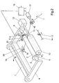
- Figures 1 and 2 is an embodiment of an inventive Winder shown, such as in a texturing machine is inserted.
- the winding device according to the invention Winding the thread shown. 2
- the winding device is after the bobbin change when threading is shown.
- the following Description applies to both Figures 1 and 2, insofar as not expressly to one the figures are referenced.
- the winding device has a pivotable bobbin holder 4 which a pivot axis 7 is mounted.
- the pivot axis 7 is at one Machine frame attached.
- two opposing clamping plates 5 and 6 are freely rotatable. Between the clamping plates 5 and 6 there is a sleeve 2 for receiving a coil 3 curious; excited.
- the clamping plates 5 and 6 each have a conical Centering approach that partially protrudes into the sleeve end. So that is the sleeve 2 centered between the clamping plates 5 and 6.
- the clamping plate 5 has one Catcher 8 to change the thread to the new one after a bobbin change Sleeve.
- the structure of the clamping plate 5 will be explained in more detail below described.
- a sensor 9 is provided on the coil holder 4 in the area of the clamping plate 5, which is connected to a control device 15 via a signal line.
- the Control device 15 is used to control the thread guide during the Winding and during the reel change.
- control device 15 has a drive 17 coupled, which leads a thread guide 16 for applying the thread 1.
- Driving roller 10 on.
- the drive roller 10 is connected via a drive shaft 11 to a Roller motor 12 connected.
- the roller motor 12 drives the drive roller 10 in the substantially constant speed.
- the direction of rotation is by one Arrow marked in Figures 1 to 2.
- the drive roller drives through friction the sleeve 2 or the coil 3 with a substantially constant Peripheral speed.
- Fig. List the winding device when winding the thread 1 to the bobbin 3 shown.
- the drive means can for example by a belt drive or by a Reverse thread shaft to be executed.
- Evasive movement of the constantly growing coil 3 through the coil holder 4 enables.
- a bobbin change executed executed.
- the coil holder 4 is pivoted into a change position, so that the coil 3 is out of contact with the drive roller 10.
- the thread 1 by auxiliary devices in a Hand over suction device for cutting and suction. 2 is a suction device 18 is shown as an example.
- the suction device 18 has a knife 19 and a suction connection 20.
- the knife 19 is used for cutting the thread when changing the bobbin, with the incoming thread is led through the suction connection to a yarn container.
- Fig. 2 the bobbin change is completed and the bobbin holder with a new one Sleeve 2 pivoted back into its operating position.
- the thread 1 is passed through the thread guide 16 in the direction of the tension plate 5 guided so that the clamping plate 5 with the catching device 8 the running thread 1st can catch.
- the drive 17 of the thread guide 16 is thereby Control device 15 activates as soon as sensor 9 reaches a predefined speed of the clamping plate 5 signals.
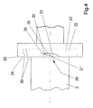
- the clamping plate has a circumferential end edge 25 which is on the sleeve 2 facing end of the clamping plate 5 is formed.
- a catch nose 27 and a catch slot 28 are formed by a recess 26.
- the Catch 27 is undercut by the recess 26 such that the tip of the Catch 27 shows in the direction of rotation of the clamping plate 5.
- the catch slot 28 has a leading edge 31, which is connected to the front edge 25 and one in Extension of the front edge 25 deflecting guidance of the thread in the Catch slot 28 caused by rotation of the clamping plate.
- the clamping body 29 is here as Ball formed by a cage extending in the radial direction 34 is freely guided on the clamping plate.
- the ball 29 is shown in FIGS. 3, 4 and 5 in shown a clamping position. In the clamping position, the ball 29 is through a centrifugal force is held on a contact surface formed by the recess 26. The centrifugal force is generated by the rotation of the clamping plate 5. Between the ball 29 and the contact surface 33, a clamping gap 32 is generated.
- the contact surface 33 is formed at the end of the catch slot 27, the End of the catch slot 27 represents a section of the contact surface 33.
- the sleeve 2 is with the sleeve end face 23 on the centering shoulder 22 of the Tension plates held.
- the centering projection 22 is through an incision 30 in the End face of the clamping plate is formed.
- Thread leading edge 24 generated on the end face of the tensioning plate 5.
- the incision 30 in the front of the clamping plate is designed such that the Thread leading edge 24 covers the sleeve end of the clamped sleeve and on a normal plane of the sleeve 2, which is at a distance from the sleeve end face 23 stretched over the sleeve.
- the thread 1 In order to catch and clamp the thread 1 when putting it on, the thread 1 is through the thread guide 16 and the suction port 20 (Fig. 2) guided such that the Thread 1 overflows the end edge 25 of the tensioning plate 5 in the oblique run.
- the thread 1 By turning the tension plate, the thread 1 is first slide along the end edge 25 until the thread 1 hits the recess 26. The thread 1 is transferred from the front edge 25 to the leading edge 31 and slides behind the catch nose 27 into the catch slot 28.
- the thread 1 With further rotation of the tension plate 5, the thread 1 is guided into the clamping gap 32 and between the clamping body 29 and the contact surface 33 clamped.
- Fig. 6 the situation immediately after the thread 1 is clamped on the Chuck 5 shown.
- the tension plate 5 By turning the tension plate 5, the thread piece between the suction port 20 and the clamping in the clamping plate 5 in the Cutting device 21 out.
- the cutting device 21 has one stationary knife through which the thread is cut.
- the clamping body 29 is located each in the clamping position.
- This clamping position is from the clamping body observed as long as the clamping plate rotates at a speed so that the resulting centrifugal force acts on the sprag and the Clamping body holds in the clamping position.
- the clamping plate is no longer turns, the clamping of the thread is released.
- this condition only occurs in the event of a bobbin change.
- the Clamping plates either due to its own weight on the contact surface remain or moved to a radially inner relief position.
- a spring is preferably used, which counteracts the centrifugal force acts on the clamping body 29. This ensures that when the Clamping plate the clamp body is pressed into its relief position and the loose thread start of the bobbin is released immediately.
- the thread guide 16 After the thread is fixed in the clamping plate 5 by the clamping body 29, the thread guide 16 will guide the thread 1 back into the traversing area.
- the thread on the front of the clamping plate is directly on the Surface of the sleeve 2 out.
- the thread winding on the sleeve 2 can kick off.
- the thread 16 is transferred to the traversing thread guide 13. It is also possible that the thread during winding and during of the catch is only guided by the traversing thread guide. This does not apply only the handover of the thread.
- the clamping plate shown in Fig. 3 to 6 is designed such that the Front edge 25 and the thread guide edge 24 lie together in a normal plane. This version is exemplary.
- the front edge 25 and the thread leading edge 24 can also be offset on the clamping plate. The only important thing here is that that is formed between the sleeve end face 23 and the clamping plate 5 Gap is covered by the thread guide edge 24.
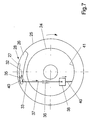
- FIG. 7 shows a further exemplary embodiment of a clamping plate.
- the Clamping plate is shown schematically in a side view, with on the front edge 25 also a catch nose 27 and a catch slot 28 through a recess 26 are trained.
- the stop 40 is through the bottom of the Nose 27 formed.
- the contact surface 33 is through a through the recess 26 opposite surface to the nose 27 formed.
- the sprag is coupled to a weight 38 via a guide element 37.
- the weight 38 is movable on the clamping plate on the side opposite to the axis arranged.
- the guide element 37 and thus the weight 38 is on the Guided tour 36. Between an incision 41 and the weight 38 is one Spring 40 tensioned.
- the guide element 37, the guide 36 and the weight 38 are preferred integrated in the clamping plate 5 without the clamping of the sleeve 2 influence.
- the weight 38 by rotating the clamping plate 5 one on the Weight 38 attacking centrifugal force cause the weight 38 to be radial corresponding to the guide 36 on the clamping plate to the outside against the spring force of Spring 40 moves.
- the movement of the Weight 38 transferred to the clamp body 35.
- the clamp body 35 will from its relief position, which is defined by the stop 40, in the The clamping position moves and forms one between itself and the contact surface 33 Clamping gap 32.
- the catch slot 28 of the catch nose 27 detected thread are clamped in the clamping gap 32.
- the winding device In the winding device according to the invention is used to fix the Thread beginning of a bobbin of thread in the between the clamping body and guided and clamped a contact surface formed clamping gap.
Landscapes
- Tension Adjustment In Filamentary Materials (AREA)
- Spinning Or Twisting Of Yarns (AREA)
- Winding Filamentary Materials (AREA)
Applications Claiming Priority (2)
| Application Number | Priority Date | Filing Date | Title |
|---|---|---|---|
| DE10010294 | 2000-03-02 | ||
| DE10010294 | 2000-03-02 |
Publications (2)
| Publication Number | Publication Date |
|---|---|
| EP1129975A2 true EP1129975A2 (fr) | 2001-09-05 |
| EP1129975A3 EP1129975A3 (fr) | 2002-12-18 |
Family
ID=7633323
Family Applications (1)
| Application Number | Title | Priority Date | Filing Date |
|---|---|---|---|
| EP01103529A Withdrawn EP1129975A3 (fr) | 2000-03-02 | 2001-02-16 | Dispostif de bobinage |
Country Status (2)
| Country | Link |
|---|---|
| EP (1) | EP1129975A3 (fr) |
| JP (1) | JP2001278544A (fr) |
Cited By (4)
| Publication number | Priority date | Publication date | Assignee | Title |
|---|---|---|---|---|
| WO2021090082A1 (fr) * | 2019-11-06 | 2021-05-14 | Stc Spinnzwirn Gmbh | Dispositif et procédé d'enroulement d'un fil |
| CN113981574A (zh) * | 2021-10-29 | 2022-01-28 | 巢湖市华锦纺织有限公司 | 一种低磨损细纱机涨力盘 |
| CN114506736A (zh) * | 2022-03-21 | 2022-05-17 | 迈得医疗工业设备股份有限公司 | 丝线输送控制方法及丝线收集设备 |
| CN116715089A (zh) * | 2023-07-19 | 2023-09-08 | 湖南思远智能装备有限公司 | 一种风电叶片螺栓套缠丝装置及方法 |
Family Cites Families (5)
| Publication number | Priority date | Publication date | Assignee | Title |
|---|---|---|---|---|
| GB830978A (en) * | 1955-06-10 | 1960-03-23 | Reiners Walter | Automatic bobbin changing thread winding machines |
| US3081044A (en) * | 1961-04-21 | 1963-03-12 | Leesona Corp | Initial strand end snagger |
| US3411726A (en) * | 1966-12-12 | 1968-11-19 | Monsanto Co | Yarn string-up roll |
| FR2200836A5 (fr) * | 1972-09-25 | 1974-04-19 | Rhone Poulenc Textile | |
| EP0916610B1 (fr) * | 1997-11-14 | 2003-04-02 | B a r m a g AG | Dispositif de bobinage |
-
2001
- 2001-02-16 EP EP01103529A patent/EP1129975A3/fr not_active Withdrawn
- 2001-03-02 JP JP2001059102A patent/JP2001278544A/ja active Pending
Cited By (8)
| Publication number | Priority date | Publication date | Assignee | Title |
|---|---|---|---|---|
| WO2021090082A1 (fr) * | 2019-11-06 | 2021-05-14 | Stc Spinnzwirn Gmbh | Dispositif et procédé d'enroulement d'un fil |
| CN113614012A (zh) * | 2019-11-06 | 2021-11-05 | Stc纺织公司 | 纱线卷绕装置和方法 |
| CN113614012B (zh) * | 2019-11-06 | 2022-12-27 | Stc纺织公司 | 纱线卷绕装置和方法 |
| US11772928B2 (en) | 2019-11-06 | 2023-10-03 | Stc Spinnzwirn Gmbh | Device and method for winding a thread |
| CN113981574A (zh) * | 2021-10-29 | 2022-01-28 | 巢湖市华锦纺织有限公司 | 一种低磨损细纱机涨力盘 |
| CN113981574B (zh) * | 2021-10-29 | 2022-08-09 | 巢湖市华锦纺织有限公司 | 一种低磨损细纱机涨力盘 |
| CN114506736A (zh) * | 2022-03-21 | 2022-05-17 | 迈得医疗工业设备股份有限公司 | 丝线输送控制方法及丝线收集设备 |
| CN116715089A (zh) * | 2023-07-19 | 2023-09-08 | 湖南思远智能装备有限公司 | 一种风电叶片螺栓套缠丝装置及方法 |
Also Published As
| Publication number | Publication date |
|---|---|
| EP1129975A3 (fr) | 2002-12-18 |
| JP2001278544A (ja) | 2001-10-10 |
Similar Documents
| Publication | Publication Date | Title |
|---|---|---|
| EP0916610B1 (fr) | Dispositif de bobinage | |
| DE2615909C2 (fr) | ||
| DE102019129966B3 (de) | Vorrichtung und Verfahren zum Aufwickeln eines Fadens | |
| EP2739555B1 (fr) | Dispositif de bobinage | |
| EP1161397B1 (fr) | Procede et dispositif pour guider et couper un fil d'alimentation lors du changement de bobines | |
| EP0916612B1 (fr) | Dispositif et procédé pour guider et couper un fil textile alimenté en continu | |
| EP0921087A2 (fr) | Procédé et dispositif de bobinage pour bobiner un fil textile alimenté en continu | |
| DE3805347A1 (de) | Aufspulmaschine | |
| DE2461621B2 (de) | Fadenschneidvorrichtung an ringspinn- und ringzwirnmaschinen | |
| EP0565899B1 (fr) | Dispositif pour couper un fil | |
| DE3923305A1 (de) | Aufspulmaschine | |
| DE2503299A1 (de) | Verfahren und vorrichtung zur steuerung einer reservewicklung beim aufspulen eines fadens auf einer spulenhuelse | |
| DE102019122337B3 (de) | Mehrfachspulenschrank zum aufspulen eines filamentes auf eine transportspule und eine pufferspule hierfür | |
| CH686669A5 (de) | Verfahren und Vorrichtung zum Wickeln einer Fadenreserve. | |
| EP0286893A1 (fr) | Méthode pour fixer un fil amené à vitesse constante à une bobine | |
| DE3512403C2 (de) | Fadenendebehandlungseinrichtung | |
| DE4334813B4 (de) | Spulvorrichtung | |
| EP1046603A2 (fr) | Dispositif et procédé pour guider et couper un fil arrivant pendant le changement de bobine | |
| DE102008041564B3 (de) | Rollenwechsler mit einer Vorrichtung zum kontrollierten Auffangen und Aufwickeln einer Restfahne einer abgelaufenen Materialrolle beim fliegenden Rollenwechsel | |
| DE19743278A1 (de) | Spulmaschine und Verfahren zum Aufwickeln eines kontinuierlich zulaufenden Fadens zu Spulen | |
| DE3713135C2 (fr) | ||
| DE4115339B4 (de) | Spulhülse | |
| CH438112A (de) | Vorrichtung zum Erfassen des Fadenanfanges eines Kopses | |
| DE10235209C1 (de) | Vorrichtung zum Fangen eines Fadens am Anfang einer Spulreise | |
| DE102011115051A1 (de) | Verfahren und Vorrichtung zum kontinuierlichen Aufwickeln eines bandförmigen Spulgutes |
Legal Events
| Date | Code | Title | Description |
|---|---|---|---|
| PUAI | Public reference made under article 153(3) epc to a published international application that has entered the european phase |
Free format text: ORIGINAL CODE: 0009012 |
|
| AK | Designated contracting states |
Kind code of ref document: A2 Designated state(s): AT BE CH CY DE DK ES FI FR GB GR IE IT LI LU MC NL PT SE TR |
|
| AX | Request for extension of the european patent |
Free format text: AL;LT;LV;MK;RO;SI |
|
| PUAL | Search report despatched |
Free format text: ORIGINAL CODE: 0009013 |
|
| AK | Designated contracting states |
Kind code of ref document: A3 Designated state(s): AT BE CH CY DE DK ES FI FR GB GR IE IT LI LU MC NL PT SE TR |
|
| AX | Request for extension of the european patent |
Free format text: AL;LT;LV;MK;RO;SI |
|
| AKX | Designation fees paid |
Designated state(s): CH DE FR GB IT LI TR |
|
| STAA | Information on the status of an ep patent application or granted ep patent |
Free format text: STATUS: THE APPLICATION IS DEEMED TO BE WITHDRAWN |
|
| 18D | Application deemed to be withdrawn |
Effective date: 20030829 |