EP1129983A2 - Flurförderzeug mit einer Hubvorrichtung - Google Patents
Flurförderzeug mit einer Hubvorrichtung Download PDFInfo
- Publication number
- EP1129983A2 EP1129983A2 EP01104624A EP01104624A EP1129983A2 EP 1129983 A2 EP1129983 A2 EP 1129983A2 EP 01104624 A EP01104624 A EP 01104624A EP 01104624 A EP01104624 A EP 01104624A EP 1129983 A2 EP1129983 A2 EP 1129983A2
- Authority
- EP
- European Patent Office
- Prior art keywords
- industrial truck
- driver
- truck according
- lifting device
- load
- Prior art date
- Legal status (The legal status is an assumption and is not a legal conclusion. Google has not performed a legal analysis and makes no representation as to the accuracy of the status listed.)
- Withdrawn
Links
Images



Classifications
-
- B—PERFORMING OPERATIONS; TRANSPORTING
- B66—HOISTING; LIFTING; HAULING
- B66F—HOISTING, LIFTING, HAULING OR PUSHING, NOT OTHERWISE PROVIDED FOR, e.g. DEVICES WHICH APPLY A LIFTING OR PUSHING FORCE DIRECTLY TO THE SURFACE OF A LOAD
- B66F9/00—Devices for lifting or lowering bulky or heavy goods for loading or unloading purposes
- B66F9/06—Devices for lifting or lowering bulky or heavy goods for loading or unloading purposes movable, with their loads, on wheels or the like, e.g. fork-lift trucks
- B66F9/075—Constructional features or details
- B66F9/08—Masts; Guides; Chains
- B66F9/082—Masts; Guides; Chains inclinable
-
- B—PERFORMING OPERATIONS; TRANSPORTING
- B66—HOISTING; LIFTING; HAULING
- B66F—HOISTING, LIFTING, HAULING OR PUSHING, NOT OTHERWISE PROVIDED FOR, e.g. DEVICES WHICH APPLY A LIFTING OR PUSHING FORCE DIRECTLY TO THE SURFACE OF A LOAD
- B66F9/00—Devices for lifting or lowering bulky or heavy goods for loading or unloading purposes
- B66F9/06—Devices for lifting or lowering bulky or heavy goods for loading or unloading purposes movable, with their loads, on wheels or the like, e.g. fork-lift trucks
- B66F9/075—Constructional features or details
- B66F9/07545—Overhead guards
-
- B—PERFORMING OPERATIONS; TRANSPORTING
- B66—HOISTING; LIFTING; HAULING
- B66F—HOISTING, LIFTING, HAULING OR PUSHING, NOT OTHERWISE PROVIDED FOR, e.g. DEVICES WHICH APPLY A LIFTING OR PUSHING FORCE DIRECTLY TO THE SURFACE OF A LOAD
- B66F9/00—Devices for lifting or lowering bulky or heavy goods for loading or unloading purposes
- B66F9/06—Devices for lifting or lowering bulky or heavy goods for loading or unloading purposes movable, with their loads, on wheels or the like, e.g. fork-lift trucks
- B66F9/075—Constructional features or details
- B66F9/08—Masts; Guides; Chains
- B66F9/10—Masts; Guides; Chains movable in a horizontal direction relative to truck
Definitions
- the invention relates to an industrial truck, in particular a forklift, with a drive axle close to the load and a steering axle remote from the load as well as a lifting device.
- Forklifts in particular counterbalance forklifts, come as industrial trucks. into consideration, in which the lifting device in the area of the near-load Drive axis are arranged. Such are in the area of the steering axle remote from the load Provide a counterweight to the forklift. Between the lifting device and the counterweight is a driver's seat, for example a driver's canopy or a Driver's cabin arranged.
- the present invention is based on the object of an industrial truck to provide the type mentioned above, the increased tipping safety having.
- the lifting device in Longitudinal direction of the truck is displaceable.
- the Lifting device and thus the load can be moved in the longitudinal direction, whereby the Load arranged in the transport position between the drive axle and the steering axle can be worn and thus worn within the contact area.
- This can the stability and thus the tipping safety of the forklift during transport the load increases in both the transverse and longitudinal directions of the forklift become.
- a driver's seat is in the area of the arranged away from the load steering axis and between the steering axis and the drive axle formed a platform on which the lifting device is mounted to be longitudinally displaceable.
- the lifting device can be opened be carried out in a simple manner in the longitudinal direction.
- the drive system of the Industrial truck to provide, such as a battery and electrical Drive motors or an internal combustion engine and a hydrostatic drive.
- the lifting device has one in the guide mounted carriage which is connected to a lifting mast.
- a Sled which is mounted in the guide to move longitudinally and with the mast in Operational connection, the lifting device can be moved longitudinally in a simple manner be formed.
- a tilt drive is expediently provided. With one of the lifting devices assigned tilt drive can pick up and set down loads be improved.
- the tilting device has at least one tilting cylinder, which is in operative connection with the carriage and the lifting mast, the lifting mast is articulated on the slide. It is also possible to be rigid on the sled attached lifting mast to provide a tiltable load handler on the lifting mast.
- the lifting mast has at least one hydraulic one Telescopic cylinder on.
- the lifting device of at least one Telescopic cylinders are formed.
- the mast has one in one Guide element that is connected to the slide, movable slide rail on.
- a guide element and a slide rail trained mast can be arranged in a simple manner on the slide rail Load handler based on the level of the platform on the floor lowered or raised from the floor to the level of the platform become.
- the slide rail can be by means of an electric drive motor or by means of a hydraulic telescopic cylinder can be driven.
- the drive axle close to the load is designed as a tandem axle, a small one can be used Height of the truck in the area of the platform achieved with high load capacity become.
- the driver's view becomes clear to a load handler attached to the mast with a low overall height Platform improved.
- the driver's position is at least partially above the distance from the load Axis is arranged.
- the driver's seat continues to serve as a counterweight.
- the driver's seat can be rotated.
- a rotatable driver's cab within which the driver's seat is arranged, can be opened simple way the driver's seat can be pivoted and achieved that the Driver in both forward and reverse travel of the truck in Direction of travel sits and looks.
- the arrangement of the driver's seat relative to The driver's cabin remains unchanged, so that the ergonomics remain the same Driver's seat for the driver a relaxed reverse drive with improved Visibility is made possible.
- the driver's cab is particularly advantageous by at least 180 degrees, preferably 360 Degrees, rotatable.
- the driver's cab can thus move from one position to the forward a position for reversing can be swiveled by 180 degrees.
- the driver's cab prefferably be in the region of the longitudinal central axis of the Forklift arranged rotating axis rotatably. This allows according to the dimensions of the driver's cab that the driver's cab at Do not rotate or protrude only slightly beyond the outline of the truck.
- the truck's stability can be increased further if the driver's cab is provided with a counterweight.
- a counterweight By arranging the driver's cabin at least partially above the steering axis and the design of the driver's cabin a counterweight can be used during picking up and putting down a load which is the lifting device outside the footprint, the stability and Tipping safety can be increased in a simple manner.
- a counterbalance forklift trained industrial truck is in the area of the steering axle on the frame a counterweight is provided on the truck, so that this is at the driver's cabin arranged counterweight represents an additional counterweight.
- the industrial truck can be equipped with an electric drive system or with a internal combustion engine drive system.
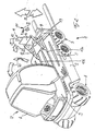
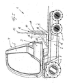
- FIGS. 1 to 3 show a counterbalance forklift 1 according to the invention trained industrial truck in a position for forward travel for receiving or shown for placing a load.
- the forklift 1 has a frame 2 with a tandem axle trained drive axle 3 and is provided with a steering axle 4. Between the Steering axis 4 and the drive axis 3 is a platform 5 which is above the Drive axis 3 is arranged.
- a frame 6 designed as a driver's cabin 6
- Driver's seat 7 arranged, which can be seen from Figure 3, by means of a Swivel joint 8, for example a slewing ring, is rotatably mounted on the frame 2.
- the vertical axis of rotation is located on the longitudinal central axis of the Forklift.
- the driver's cabin 7 is provided with a counterweight 9.
- the frame 2 of the forklift 1 is provided with a counterweight trained or provided with a counterweight.
- the Driver's cab 7 provided with a counterweight 9.
- the counterweight 9 forms here an additional counterweight, so that in accordance with in FIGS. 1 to 3 pivoted driver's cab 6 is the greatest possible counterweight in the area of Steering axis 4 is effective for receiving or depositing a load.
- the driver's cabin 6 is thus - as shown in FIG. 2 - in the direction of the arrows 20 swiveling.
- Within the driver's cab 6 are a in a manner not shown Driver's seat, a steering device and control levers for work equipment arranged.
- a lifting device 10 is mounted on the platform 5 so as to be longitudinally displaceable.
- the Lifting device 10 has a lifting mast 11, which with a carriage 12 in Connection is established.
- the carriage 12 is in two spaced-apart guides 13a, 13b mounted to be longitudinally displaceable.
- the guides 13a, 13b are here on the Platform 5 formed, and arranged in the longitudinal direction of the forklift 1.
- the carriage 12 can, for example, be driven below the platform Hydraulic cylinders can be provided.
- a load handler 14 arranged, for example a fork carriage with two fork tines.
- the lifting mast 11 is designed, for example, as a slide rail 15, which is inside of a guide element 16, which is connected to the carriage 12, vertically is slidably mounted.
- a hydraulic can drive the slide rail 15 Telescopic cylinder or an electric motor can be provided.
- the load suspension device 14 can be inclined.
- guide element 16 is articulated in the lower area on the slide 12, for example by means of a swivel joint 18.
- the tilting device 17 has two Tilt cylinder 19, which are articulated on the slide 12 and on the guide element 16.
- the load suspension device 14 can thus - as shown in Figure 2 - in the direction of Arrows 21 can be raised and lowered.
- the mast 11 is in the direction of the arrows 22 tiltable and the lifting device 10 in the direction of the arrows 23 longitudinally displaceable.
- the driver's cabin 6 In the position shown in FIGS. 1 to 3, the driver's cabin 6 is located in a forward swiveled position for driving forward, causing the driver to move in Direction to the lifting device 10 and thus looks towards the load.
- the Lifting device 10 is fully extended in the direction of drive axis 3 whereby the load-carrying means 14 outside the contact area of the Forklift 1 is located and arranged in the guide member 16 Slide rail 15 can be lowered to the floor.
- the driver's cabin 6 arranged counterweight 9 is in such a pivoted driver's cab 6 in the area of the forklift 1 opposite the load, which results in a high Load capacity and tipping safety can be achieved.
- the load handling device 14 After picking up the load from the floor or placing the load on the floor the load handling device 14 is raised to the level of the platform 5, whereby the carriage 12 can be moved in the direction of the steering axis 4.
- the forklift is in a position for reversing, in the load can be transported, especially over long distances.
- the Lifting device 10 is here in the fully retracted position, so that the center of gravity of the load picked up on the load suspension device 14 within that formed by the drive axle 3 and the steering axle 4 Footprint is arranged. This results in the load being transported a high level of safety against tipping of the forklift 1.
- the driver's cabin 6 is 180 ° from the position for forward travel pivoted so that the driver is also in this position for reversing Direction of travel looks and thus the driver's view while transporting the load is not hindered by the load and the lifting device 10, which makes a more secure Operation of the forklift results.
Landscapes
- Engineering & Computer Science (AREA)
- Transportation (AREA)
- Structural Engineering (AREA)
- Civil Engineering (AREA)
- Life Sciences & Earth Sciences (AREA)
- Geology (AREA)
- Mechanical Engineering (AREA)
- Forklifts And Lifting Vehicles (AREA)
Abstract
Description
- Figur 1
- ein erfindungsgemäßes Flurförderzeug in einer perspektivischen Darstellung in einer Stellung für die Vorwärtsfahrt,
- Figur 2
- ein Flurförderzeug gemäß Figur 1 in einer weiteren perspektivischen Darstellung,
- Figur 3
- ein Flurförderzeug gemäß Figur 1 in einer Seitenansicht,
- Figur 4
- ein erfindungsgemäßes Flurförderzeug in einer perspektivischen Darstellung in einer Stellung für die Rückwärtsfahrt und
- Figur 5
- ein Flurförderzeug gemäß Figur 4 in einer Seitenansicht.
Claims (19)
- Flurförderzeug, insbesondere Gabelstapler, mit einer lastnahen Antriebsachse und einer lastfernen Lenkachse sowie einer Hubvorrichtung, dadurch gekennzeichnet, daß die Hubvorrichtung (10) in Längsrichtung des Flurförderzeugs verschiebbar ist.
- Flurförderzeug nach Anspruch 1, dadurch gekennzeichnet, daß ein Fahrerplatz (7) im Bereich der lastfernen Lenkachse (4) angeordnet ist und zwischen der Lenkachse (4) und der Antriebsachse (3) eine Plattform (5) ausgebildet ist, auf der die Hubvorrichtung (10) längsverschiebbar gelagert ist.
- Flurförderzeug nach Anspruch 2, dadurch gekennzeichnet, daß die Plattform (5) mit zumindest einer Führung (13a; 13b) versehen ist, in der die Hubvorrichtung (10) verschiebbar gelagert ist.
- Flurförderzeug nach Anspruch 3, dadurch gekennzeichnet, daß die Hubvorrichtung (10) einen in der Führung (13a; 13b) gelagerten Schlitten (12) aufweist, der mit einem Hubmast (11) in Verbindung steht.
- Flurförderzeug nach einem der Ansprüche 1 bis 4, dadurch gekennzeichnet, daß eine Neigevorrichtung (17) vorgesehen ist.
- Flurförderzeug nach Anspruch 5, dadurch gekennzeichnet, daß die Neigevorrichtung (17) zumindest einen Neigezylinder (19) aufweist, der mit dem Schlitten (12) und dem Hubmast (11) in Wirkverbindung steht, wobei der Hubmast (11) am Schlitten (12) gelenkig gelagert ist.
- Flurförderzeug nach einem der Ansprüche 1 bis 6, dadurch gekennzeichnet, daß der Hubmast (11) zumindest einen hydraulischen Teleskopzylinder aufweist.
- Flurförderzeug nach einem der Ansprüche 1 bis 6, dadurch gekennzeichnet, daß der Hubmast (11) eine in einem Führungselement (16), das mit dem Schlitten (12) in Wirkverbindung steht, verschiebbare Gleitschiene (15) aufweist.
- Flurförderzeug nach Anspruch 8, dadurch gekennzeichnet, daß die Gleitschiene (15) mittels eines elektrischen Antriebsmotors antreibbar ist.
- Flurförderzeug nach Anspruch 8, dadurch gekennzeichnet, daß die Gleitschiene (15) mittels eines Teleskopzylinders antreibbar ist.
- Flurförderzeug nach einem der Ansprüche 1 bis 10, dadurch gekennzeichnet, daß die Antriebsachse (3) als Tandemachse ausgebildet ist.
- Flurförderzeug nach einem der Ansprüche 1 bis 11, dadurch gekennzeichnet, daß der Fahrerplatz (7) zumindest teilweise über der Lenkachse (4) angeordnet ist.
- Flurförderzeug nach einem der Ansprüche 1 bis 12, dadurch gekennzeichnet, daß der Fahrerplatz (7) drehbar ist.
- Flurförderzeug nach Anspruch 13, dadurch gekennzeichnet, daß die Fahrerplatz (7) um 180 Grad drehbar ist.
- Flurförderzeug nach Anspruch 13 oder 14, dadurch gekennzeichnet, daß der Fahrerplatz (7) um eine im Bereich der Längsmittelachse des Flurförderzeugs angeordnete Drehachse drehbar gelagert ist.
- Flurförderzeug nach einem der Ansprüche 1 bis 15, dadurch gekennzeichnet, daß der Fahrerplatz (7) als Fahrerkabine (6) ausgebildet ist
- Flurförderzeug nach Anspruch 16, dadurch gekennzeichnet, daß die Fahrerkabine (6) mit einem Gegengewicht (9) versehen ist.
- Flurförderzeug nach einem der Ansprüche 1 bis 17, dadurch gekennzeichnet, daß das Flurförderzeug ein elektrisches Antriebssystem aufweist.
- Flurförderzeug nach einem der Ansprüche 1 bis 17, dadurch gekennzeichnet, daß das Flurförderzeug ein verbrennungsmotorisches Antriebssystem aufweist.
Applications Claiming Priority (4)
| Application Number | Priority Date | Filing Date | Title |
|---|---|---|---|
| DE10009641 | 2000-03-01 | ||
| DE10009641 | 2000-03-01 | ||
| DE10013083 | 2000-03-17 | ||
| DE10013083A DE10013083A1 (de) | 2000-03-01 | 2000-03-17 | Flurförderzeug mit einer Hubvorrichtung |
Publications (2)
| Publication Number | Publication Date |
|---|---|
| EP1129983A2 true EP1129983A2 (de) | 2001-09-05 |
| EP1129983A3 EP1129983A3 (de) | 2004-07-07 |
Family
ID=26004588
Family Applications (1)
| Application Number | Title | Priority Date | Filing Date |
|---|---|---|---|
| EP01104624A Withdrawn EP1129983A3 (de) | 2000-03-01 | 2001-02-23 | Flurförderzeug mit einer Hubvorrichtung |
Country Status (1)
| Country | Link |
|---|---|
| EP (1) | EP1129983A3 (de) |
Cited By (3)
| Publication number | Priority date | Publication date | Assignee | Title |
|---|---|---|---|---|
| FR2852308A1 (fr) * | 2003-03-13 | 2004-09-17 | Bernard Coeuret | Chariot transporteur/elevateur |
| EP2377806A1 (de) * | 2010-04-14 | 2011-10-19 | MDB S.r.L. con Socio Unico | Gabelstapler |
| EP4067288A1 (de) * | 2021-03-30 | 2022-10-05 | Karlsruher Institut für Technologie | Hebe- und verfahrvorrichtung |
Family Cites Families (8)
| Publication number | Priority date | Publication date | Assignee | Title |
|---|---|---|---|---|
| GB793972A (en) * | 1955-10-03 | 1958-04-23 | Lifting Gear Services Ltd | Improvements in and relating to reach-fork stackers |
| GB988565A (en) * | 1960-05-13 | 1965-04-07 | Lansing Bagnall Ltd | Improvements in or relating to industrial lift trucks |
| SE426937B (sv) * | 1981-07-03 | 1983-02-21 | Knut Jacobsson | Forfarande och anordning for att astadkomma vendning av ett lastobjekt kring en i huvudsak vertikal axel |
| US4778327A (en) * | 1984-09-14 | 1988-10-18 | Western Waste Industries | Bin lifting mechanism |
| FR2664556B1 (fr) * | 1990-07-10 | 1993-07-30 | Brissaud Dominique | Engin de manutention a cabine tournante. |
| SE469426B (sv) * | 1991-11-18 | 1993-07-05 | Bt Ind Ab | Skjutstativtruck med lutningsbar foerarplats |
| DE19819270B4 (de) * | 1997-05-02 | 2005-04-07 | Radosav Nikolic | Seitenstapler |
| JP2001089091A (ja) * | 1999-09-22 | 2001-04-03 | Kioritz Corp | 運搬車用荷積み装置 |
-
2001
- 2001-02-23 EP EP01104624A patent/EP1129983A3/de not_active Withdrawn
Cited By (3)
| Publication number | Priority date | Publication date | Assignee | Title |
|---|---|---|---|---|
| FR2852308A1 (fr) * | 2003-03-13 | 2004-09-17 | Bernard Coeuret | Chariot transporteur/elevateur |
| EP2377806A1 (de) * | 2010-04-14 | 2011-10-19 | MDB S.r.L. con Socio Unico | Gabelstapler |
| EP4067288A1 (de) * | 2021-03-30 | 2022-10-05 | Karlsruher Institut für Technologie | Hebe- und verfahrvorrichtung |
Also Published As
| Publication number | Publication date |
|---|---|
| EP1129983A3 (de) | 2004-07-07 |
Similar Documents
| Publication | Publication Date | Title |
|---|---|---|
| EP0071796A1 (de) | Knicklenker mit querverschiebbarem Gegengewicht | |
| DE69806316T2 (de) | Wagen mit Hubmast, geeignet zur Montage an das Ende eines Transportfahrzeugs | |
| DE3017456A1 (de) | Hochregalstapler | |
| DE1924968A1 (de) | Zusatzgeraet,insbesondere fuer Gabelstapler einschliesslich Seitenlader | |
| DE3047132A1 (de) | Mehrzweckfahrzeug | |
| DE3534626C2 (de) | ||
| DE60115581T2 (de) | Gabelhubwagen | |
| DE2149410A1 (de) | Vorder- und Seitenladevorrichtung | |
| DE2017624A1 (de) | Lasttragwagen für schmale Gänge | |
| DE2319408A1 (de) | Batteriebetriebener gabelstapler | |
| DE1781246A1 (de) | Gabelstapler | |
| DE2739325A1 (de) | Verladefahrzeug | |
| DE19545433A1 (de) | Hebe- und Versetzvorrichtung zur Handhabung von plattenförmigen Gegenständen | |
| DE1291683B (de) | Hublader mit verschiebbarem und vollstaendig drehbarem Hubmast | |
| DE69222738T2 (de) | Fahrzeug zum Stapeln von Lasten | |
| DE952428C (de) | Gabelstapler mit einem einen teleskopischen Mast tragenden Fahrgestell | |
| EP1129981A2 (de) | Flurförderzeug mit einer Fahrerkabine | |
| DE10013083A1 (de) | Flurförderzeug mit einer Hubvorrichtung | |
| WO2018018061A1 (de) | Selbstfahrendes flurfördergerät | |
| AT504031A1 (de) | Transportgerät | |
| EP3412620B1 (de) | Aufbaukran und aufbaukransystem | |
| DE69319398T2 (de) | Handhabungsfahrzeug | |
| DE2811797A1 (de) | Vorrichtung zum verladen von guetern | |
| DE10013082A1 (de) | Flurförderzeug mit einer Fahrerkabine | |
| EP2518005B1 (de) | Flurförderzeug |
Legal Events
| Date | Code | Title | Description |
|---|---|---|---|
| PUAI | Public reference made under article 153(3) epc to a published international application that has entered the european phase |
Free format text: ORIGINAL CODE: 0009012 |
|
| AK | Designated contracting states |
Kind code of ref document: A2 Designated state(s): AT BE CH CY DE DK ES FI FR GB GR IE IT LI LU MC NL PT SE TR |
|
| AX | Request for extension of the european patent |
Free format text: AL;LT;LV;MK;RO;SI |
|
| RIC1 | Information provided on ipc code assigned before grant |
Ipc: 7B 66F 9/08 B Ipc: 7B 66F 9/075 B Ipc: 7B 66F 9/10 A |
|
| PUAL | Search report despatched |
Free format text: ORIGINAL CODE: 0009013 |
|
| AK | Designated contracting states |
Kind code of ref document: A3 Designated state(s): AT BE CH CY DE DK ES FI FR GB GR IE IT LI LU MC NL PT SE TR |
|
| AX | Request for extension of the european patent |
Extension state: AL LT LV MK RO SI |
|
| AKX | Designation fees paid | ||
| REG | Reference to a national code |
Ref country code: DE Ref legal event code: 8566 |
|
| STAA | Information on the status of an ep patent application or granted ep patent |
Free format text: STATUS: THE APPLICATION IS DEEMED TO BE WITHDRAWN |
|
| 18D | Application deemed to be withdrawn |
Effective date: 20050108 |