EP1130150A2 - Näheinheit zum Herstellen von Falten and Abnähern - Google Patents
Näheinheit zum Herstellen von Falten and Abnähern Download PDFInfo
- Publication number
- EP1130150A2 EP1130150A2 EP01104971A EP01104971A EP1130150A2 EP 1130150 A2 EP1130150 A2 EP 1130150A2 EP 01104971 A EP01104971 A EP 01104971A EP 01104971 A EP01104971 A EP 01104971A EP 1130150 A2 EP1130150 A2 EP 1130150A2
- Authority
- EP
- European Patent Office
- Prior art keywords
- folding
- sewing
- stop bar
- folded
- edge
- Prior art date
- Legal status (The legal status is an assumption and is not a legal conclusion. Google has not performed a legal analysis and makes no representation as to the accuracy of the status listed.)
- Withdrawn
Links
- 238000009958 sewing Methods 0.000 title claims abstract description 52
- 239000000463 material Substances 0.000 claims abstract description 44
- 238000012546 transfer Methods 0.000 claims abstract description 6
- 238000000034 method Methods 0.000 claims description 2
- 238000012937 correction Methods 0.000 abstract description 5
- 230000001419 dependent effect Effects 0.000 abstract 1
- 238000004519 manufacturing process Methods 0.000 description 2
- 238000012545 processing Methods 0.000 description 2
- 230000015572 biosynthetic process Effects 0.000 description 1
- 238000011161 development Methods 0.000 description 1
- 230000000694 effects Effects 0.000 description 1
- 239000004744 fabric Substances 0.000 description 1
Images


Classifications
-
- D—TEXTILES; PAPER
- D05—SEWING; EMBROIDERING; TUFTING
- D05B—SEWING
- D05B39/00—Workpiece carriers
-
- D—TEXTILES; PAPER
- D05—SEWING; EMBROIDERING; TUFTING
- D05B—SEWING
- D05B35/00—Work-feeding or -handling elements not otherwise provided for
- D05B35/08—Work-feeding or -handling elements not otherwise provided for for ruching, gathering, casing, or filling lace, ribbons, or bindings; Pleating devices; Cuttlers; Gathering feet; Crimpers; Curlers; Rufflers
Definitions
- the invention relates to a sewing unit according to the preamble of Claim 1.
- From DE-PS 1 660 839 is a sewing unit for the manufacture of Darts known.
- the sewing unit contains a between a receiving position and a transfer position for the folding tool that can be moved, a resilient folding auxiliary sheet, holding means in the form of a Needle bar for the folded dart and a pressure rail for Takeover of the folded sewing material and for guiding during the sewing process.
- the folding tool is in its angular position relative to the Adjustable pressure rail to achieve a certain dart depth.
- the folding tool pushes the material in under its forward movement through the resilient folding auxiliary sheet and the raised pressure rail so far that the dart on the back of the pressure rail protrudes, depending on the preselected angular position of the folding tool, d. H. according to the desired dart depth.
- the needle bar becomes after the feed movement of the folding tool moved downwards, with their needles sewing material in the area of the fold grasp and fix on a sewing table top.
- DE 295 14 185 U1 is a sewing unit for the manufacture of Folding and darts known, in which the folding tool resiliently a rotatable stop disc, through which the folding or Dart depth is adjustable.
- this adjustment device for the folding tool is that the stop washer has stepless control curve and a stepper motor is finely adjustable. This way, when you switch from thin to thick or vice versa from thick to thin material Deviation of the actual intersection of the dart seam with the outside the sewing material folding edge corrected from the target intersection become.
- Carrying out such a correction is very simplified still the need, if necessary, such a correction to have to do at all. Furthermore, it is still necessary sew at least one sample piece to be able to check whether the chosen correction value was sufficient.
- the invention is therefore based on the object of handling a still trained according to the preamble of claim 1 sewing unit to further simplify.
- the task is characterized by the Feature of claim 1 solved.
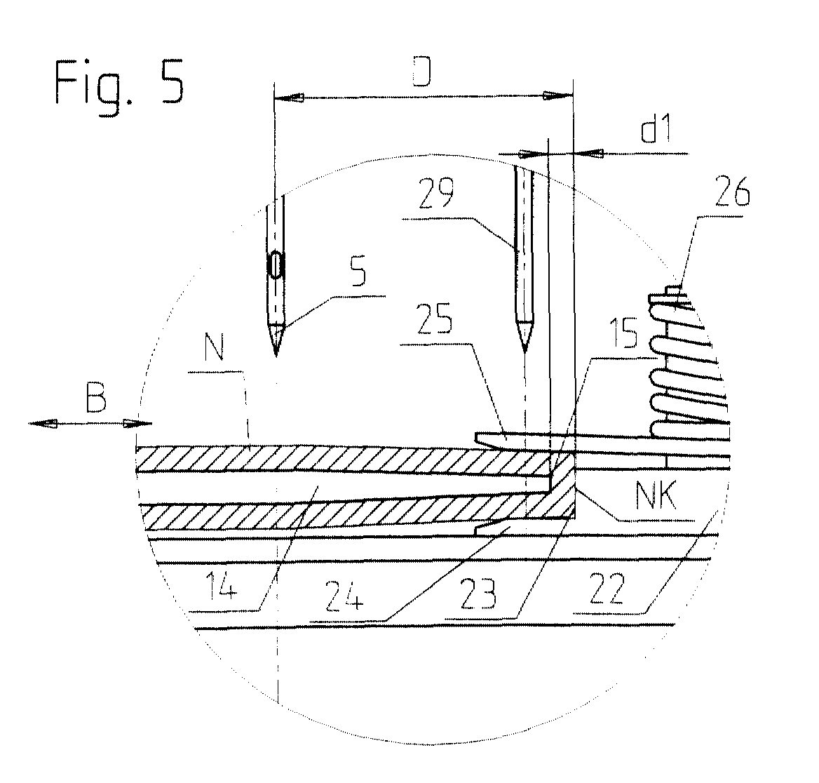
- the sling gear for limiting the Feed movement of the folding tool in the movement path of the folded material surrounding part of the folding edge of the folding tool and to be arranged directly in the path of the material folding edge achieved that the path length of this feed movement from the material itself is influenced, with the position of the sling unchanged the outside of the fabric folding edge for both thin and thick material is always the same distance from the needle, while the folding tool by the measure of the respective thickness of the sewing material in to a certain extent self-adjusting in front of the stop bar Stand comes. This ensures that regardless of the respective material thickness and without any corrective measures the actual point of intersection of the dart seam with the outside of the material folding edge always coincides exactly with the target intersection.
- the sewing unit has a table top 2 carried by a frame 1 on. On the table top 2, a sewing machine 3 is arranged, the one contains up and down movable needle bar 4 with a needle 5.
- the sewing unit has the shape of the one to be produced Seam determining pressure rail 6 on between two Rollers 7 can be passed.
- the pressure rail 6 and the rollers 7 are movable up and down with the help of two pressure cylinders 8.
- By not Drive means shown is the pressure rail 6 in its longitudinal direction slidable, whereby, as already mentioned, between the Rollers 7 is moved through.
- a guide rail 9 for a slide 10 is on the frame 1 attached.
- the piston rod 11 of an air cylinder engages on the slide 10 12 on.
- On the sled 10 is an upward projecting carrier 13 attached to which is parallel to the table top plane extending plate-shaped folding ruler 14 is arranged is.
- the edge of the folding ruler 14 facing the pressure rail 6 forms a folded edge 15.
- a bracket 16 attached to the table top 2 is a Guide rail 17 attached, which in turn a carriage 18, wearing.
- the carriage 18 is connected to a threaded spindle 19 Positioning motor 20 in drive connection.
- a rod 21 with an L-shaped cross section is attached to the slide 18, whose horizontally extending leg is transverse to the movement path B the folding edge 15 of the folding ruler 14 extending stop bar 22 for the folding ruler 14 forms.
- On the stop bar 22 is one of the abutting surface 23 projecting flat in the vertical plane Folding auxiliary bar 24 is formed.
- a compressed air cylinder 27 is arranged, the Piston rod a holding bar running parallel to the stop bar 22 28 for a plurality of holding needles 29 carries.
- the holding needles 29 are corresponding in the upper folding aid bar 25, not shown through holes assigned.
- Holding needles 29 corresponding number of passage slots, not shown formed for the holding needles 29, which differ from the Extend folding edge 15 starting transversely to this.
- the operator places the sewing material N on which, for. B. a dart to be formed on the one in the starting position Folding ruler 14 according to FIGS. 1 and 3, with part of the sewing material N hangs over the folded edge 15.
- the holding needles 29 in the Sewing material N is lowered, which makes it easier when the Folding rulers 14 is held securely. Then the print bar 6 moved in the longitudinal direction to the sewing machine 3 and then this switched on, whereupon the dart seam is formed.
Landscapes
- Engineering & Computer Science (AREA)
- Textile Engineering (AREA)
- Sewing Machines And Sewing (AREA)
- Treatment Of Fiber Materials (AREA)
Abstract
Description
- Fig. 1
- eine Teilansicht einer Näheinheit;
- Fig. 2
- einen vergrößerten Ausschnitt aus Fig. 1, in dem die Anschlagleiste und zwei Falthilfsleisten dargestellt sind;
- Fig. 3
- eine vergrößerte Teilansicht der Näheinheit mit in Ausgangsstellung befindlichem Faltlineal das ein Nähgutteil trägt;
- Fig. 4
- eine noch stärker vergrößerte Teilansicht der Näheinheit mit in Faltstellung befindlichem Faltlineal, und
- Fig. 5 und 6
- je einen vergrößerten Ausschnitt aus Fig. 4, in dem die Situation bei der Verarbeitung von unterschiedlich dickem Nähgut dargestellt ist.
Claims (6)
- Näheinheit zum Herstellen von Falten und Abnähern mit einer Nähmaschine (3), einem zwischen einer Aufnahmestellung und einer Übergabestellung für das Nähgut bewegbaren Faltwerkzeug (14), das eine Faltkante (15) aufweist, mit einem Anschlagmittel zur Begrenzung der Zuführbewegung des Faltwerkzeuges (14) in der Übergabestellung, mit Haltemitteln (29) für die gebildete Falte bzw. den Abnäher und mit einer Druckschiene (6) zur Übernahme des gefalteten Nähgutes in der Übergabestellung und zum Führen des Nähgutes während des Nähvorganges, dadurch gekennzeichnet, daß das Anschlagmittel (22) in der Bewegungsbahn (B) des vom gefalteten Nähgut umgebenen Teils der Faltkante (15) des Faltwerkzeuges (14) liegt.
- Näheinheit nach Anspruch 1, dadurch gekennzeichnet, daß das Anschlagmittel von einer im wesentlich quer zur Bewegungsbahn (B) der Faltkante (15) des Faltwerkzeuges (14) verlaufenden Anschlagleiste (22) gebildet und der parallel zur Bewegungsbahn (B) der Faltkante (15) des Faltwerkzeuges (14) gemessene Abstand der Anschlagleiste (22) zur Nadel (5) der Nähmaschine (3) veränderbar ist.
- Näheinheit nach Anspruch 2, dadurch gekennzeichnet, daß die Anschlagleiste (22) über eine Gewindespindel (19) mit einer Positioniereinrichtung (20) in Antriebsverbindung steht.
- Näheinheit nach einem oder mehreren der Ansprüche 1 bis 3, dadurch gekennzeichnet, daß der Anschlagleiste (22) wenigstens eine mit ihr verbundene Falthilfsleiste (24; 25) zugeordnet ist, die sich im wesentlichen horizontal und dabei ebenfalls quer zur Bewegungsbahn (B) der Faltkante (15) erstreckt.
- Näheinheit nach Anspruch 4, dadurch gekennzeichnet, daß die Anschlagleiste (22) zwei einen gegenseitigen Abstand aufweisende übereinander angeordnete Falthilfsleisten (24, 25) aufweist, von denen die obere mit Hilfe eines Federmechanismus (26) in einer Ruhestellung gehalten ist, aus der sie beim Einfahren des Faltwerkzeuges (14) zwischen die beiden Falthilfsleisten (24, 25) nach aufwärts bewegbar ist.
- Näheinheit nach Anspruch 4 und 5, dadurch gekennzeichnet, daß die Anschlagleiste (22) mit den Falthilfsleisten (24, 25) und die Haltemittel (29) für die gebildete Falte auf einem gemeinsamen schienengeführten Schlitten (18) angeordnet sind, der mit der Gewindespindel (19) verbunden ist.
Applications Claiming Priority (2)
| Application Number | Priority Date | Filing Date | Title |
|---|---|---|---|
| DE2000111162 DE10011162C1 (de) | 2000-03-03 | 2000-03-03 | Näheinheit zum Herstellen von Falten und Abnähern |
| DE10011162 | 2000-03-03 |
Publications (2)
| Publication Number | Publication Date |
|---|---|
| EP1130150A2 true EP1130150A2 (de) | 2001-09-05 |
| EP1130150A3 EP1130150A3 (de) | 2002-07-24 |
Family
ID=7633889
Family Applications (1)
| Application Number | Title | Priority Date | Filing Date |
|---|---|---|---|
| EP01104971A Withdrawn EP1130150A3 (de) | 2000-03-03 | 2001-03-01 | Näheinheit zum Herstellen von Falten and Abnähern |
Country Status (6)
| Country | Link |
|---|---|
| EP (1) | EP1130150A3 (de) |
| JP (1) | JP2001259273A (de) |
| BR (1) | BR0100814A (de) |
| DE (1) | DE10011162C1 (de) |
| MX (1) | MXPA01002182A (de) |
| TR (1) | TR200100526A2 (de) |
Cited By (3)
| Publication number | Priority date | Publication date | Assignee | Title |
|---|---|---|---|---|
| CN108625050A (zh) * | 2018-07-03 | 2018-10-09 | 宁波申洲针织有限公司 | 一种口袋盖自动拼合修剪一体机及其使用方法 |
| CN111705438A (zh) * | 2020-07-10 | 2020-09-25 | 广东溢达纺织有限公司 | 裁片辅助折叠装置以及裁片加工设备 |
| CN114454490A (zh) * | 2022-02-14 | 2022-05-10 | 浙江伊鲁博生物科技有限公司 | 一种口罩机用手抓指模具 |
Family Cites Families (9)
| Publication number | Priority date | Publication date | Assignee | Title |
|---|---|---|---|---|
| DE1660839B1 (de) * | 1967-09-26 | 1971-05-27 | Duerkoppwerke | Nähanlage zum Nähen von Abnähern |
| DE1760466A1 (de) * | 1968-05-22 | 1972-02-03 | Duerkoppwerke | Faltlineal fuer Arbeitsstuecke aus duennem,biegsamem Material |
| DE8027080U1 (de) * | 1980-10-10 | 1981-01-22 | Pfaff Industriemaschinen Gmbh, 6750 Kaiserslautern | Vorrichtung zum herstellen von abnaehern an zuschnitteilen von bekleidungsstuecken |
| JPH0335271Y2 (de) * | 1987-10-31 | 1991-07-25 | ||
| JP2513050Y2 (ja) * | 1991-06-27 | 1996-10-02 | ヤマトミシン製造株式会社 | 二つ折り布地縫着用ミシンの布端案内装置 |
| JPH0591570U (ja) * | 1992-05-16 | 1993-12-14 | ヤマトミシン製造株式会社 | ボタン付けミシン |
| DE29514185U1 (de) * | 1995-09-05 | 1995-10-26 | G.M. Pfaff Ag, 67655 Kaiserslautern | Einstellvorrichtung für eine Faltschiene an einer Nähmaschine |
| DE29902391U1 (de) * | 1999-02-10 | 1999-05-12 | G. M. Pfaff AG, 67655 Kaiserslautern | Faltvorrichtung an einer Näheinheit |
| JP4061424B2 (ja) * | 1999-07-31 | 2008-03-19 | ヤマトミシン製造株式会社 | ミシンの生地折返し案内装置 |
-
2000
- 2000-03-03 DE DE2000111162 patent/DE10011162C1/de not_active Expired - Fee Related
-
2001
- 2001-02-28 MX MXPA01002182 patent/MXPA01002182A/es active IP Right Grant
- 2001-02-28 TR TR2001/00526A patent/TR200100526A2/xx unknown
- 2001-03-01 EP EP01104971A patent/EP1130150A3/de not_active Withdrawn
- 2001-03-02 BR BR0100814A patent/BR0100814A/pt not_active IP Right Cessation
- 2001-03-02 JP JP2001058385A patent/JP2001259273A/ja active Pending
Cited By (5)
| Publication number | Priority date | Publication date | Assignee | Title |
|---|---|---|---|---|
| CN108625050A (zh) * | 2018-07-03 | 2018-10-09 | 宁波申洲针织有限公司 | 一种口袋盖自动拼合修剪一体机及其使用方法 |
| CN108625050B (zh) * | 2018-07-03 | 2023-04-28 | 宁波申洲针织有限公司 | 一种口袋盖自动拼合修剪一体机及其使用方法 |
| CN111705438A (zh) * | 2020-07-10 | 2020-09-25 | 广东溢达纺织有限公司 | 裁片辅助折叠装置以及裁片加工设备 |
| CN114454490A (zh) * | 2022-02-14 | 2022-05-10 | 浙江伊鲁博生物科技有限公司 | 一种口罩机用手抓指模具 |
| CN114454490B (zh) * | 2022-02-14 | 2023-09-12 | 浙江伊鲁博生物科技有限公司 | 一种口罩机用手抓指模具 |
Also Published As
| Publication number | Publication date |
|---|---|
| DE10011162C1 (de) | 2001-10-11 |
| JP2001259273A (ja) | 2001-09-25 |
| BR0100814A (pt) | 2001-11-06 |
| TR200100526A2 (tr) | 2001-12-21 |
| MXPA01002182A (es) | 2004-07-30 |
| EP1130150A3 (de) | 2002-07-24 |
Similar Documents
| Publication | Publication Date | Title |
|---|---|---|
| EP1278903B1 (de) | Nähvorrichtung | |
| DE2130642C3 (de) | Näheinrichtung zur Herstellung von paspelierten Öffnungen, insbesondere von Taschenschlitzen in Oberbekleidungen | |
| DE2709738A1 (de) | Brennschneidmaschine | |
| CH681093A5 (de) | ||
| DE7525743U (de) | Einrichtung zum herstellen von paspeloeffnungen in zuschnitteilen von bekleidungsstuecken | |
| DE3531895C1 (de) | Vorrichtung zur UEbertragung eines Paspelstreifens | |
| DE3314717C1 (de) | Naehmaschine mit mindestens einem Stoffschieber und einer Fuehrungsvorrichtung zum selbsttaetigen Herstellen einer kurvenfoermigen,randparallelen Naht | |
| DE3016676C2 (de) | Automatische Nähanlage zum randgleichen Zusammennähen zweier Nähgutanlagen | |
| DE10003133A1 (de) | Nähautomat | |
| DE10011162C1 (de) | Näheinheit zum Herstellen von Falten und Abnähern | |
| DE29709523U1 (de) | Faltvorrichtung für einen Nähautomaten | |
| DE2643106C2 (de) | Nähvorrichtung zum automatischen Nähen einander gegenüberliegender Ränder eines Stoffteils | |
| DE4029891C1 (de) | ||
| DE3033186C2 (de) | Vorrichtung zur Ausbildung eines Saumes an einem schlauchförmigen, Verdickungen aufweisenden Nähgutstück mit Blindsticken an einer Nähmaschine | |
| CH679408A5 (de) | ||
| DE4033470C1 (de) | ||
| DE2629117C2 (de) | Nähmaschine mit einer Faltvorrichtung | |
| DE3443314C2 (de) | ||
| DE2940552A1 (de) | Fuehrungsvorrichtung an naehmaschinen mit einem drueckerfuss zum vernaehen ungleich dicker stofflagen | |
| DE2244205C2 (de) | Nähmaschine zum Herstellen von Stoffstreifen vorbestimmter Länge | |
| EP1112401B1 (de) | Näheinheit zum aufnähen von umzubuggenden oder vorgebuggten taschen | |
| DE2653790A1 (de) | Verfahren und vorrichtung zum lagenlegen von karostoffen | |
| DE2325669C3 (de) | Vorrichtung zur Herstellung von paspelierten öffnungen in Bekleidungsstücken | |
| DE10136767A1 (de) | Kehlmaschine sowie Verfahren zur Einstellung wenigstens einer der Spindeln der Kehlmaschine | |
| DE2939025C2 (de) | Nähvorrichtung |
Legal Events
| Date | Code | Title | Description |
|---|---|---|---|
| PUAI | Public reference made under article 153(3) epc to a published international application that has entered the european phase |
Free format text: ORIGINAL CODE: 0009012 |
|
| AK | Designated contracting states |
Kind code of ref document: A2 Designated state(s): AT BE CH CY DE DK ES FI FR GB GR IE IT LI LU MC NL PT SE TR |
|
| AX | Request for extension of the european patent |
Free format text: AL;LT;LV;MK;RO;SI |
|
| PUAL | Search report despatched |
Free format text: ORIGINAL CODE: 0009013 |
|
| AK | Designated contracting states |
Kind code of ref document: A3 Designated state(s): AT BE CH CY DE DK ES FI FR GB GR IE IT LI LU MC NL PT SE TR |
|
| AX | Request for extension of the european patent |
Free format text: AL;LT;LV;MK;RO;SI |
|
| RAP1 | Party data changed (applicant data changed or rights of an application transferred) |
Owner name: PFAFF INDUSTRIE MASCHINEN AG |
|
| 17P | Request for examination filed |
Effective date: 20021220 |
|
| AKX | Designation fees paid |
Designated state(s): DE ES IT PT |
|
| GRAP | Despatch of communication of intention to grant a patent |
Free format text: ORIGINAL CODE: EPIDOSNIGR1 |
|
| STAA | Information on the status of an ep patent application or granted ep patent |
Free format text: STATUS: THE APPLICATION IS DEEMED TO BE WITHDRAWN |
|
| 18D | Application deemed to be withdrawn |
Effective date: 20060712 |