EP1130167A2 - Poller - Google Patents
Poller Download PDFInfo
- Publication number
- EP1130167A2 EP1130167A2 EP01105289A EP01105289A EP1130167A2 EP 1130167 A2 EP1130167 A2 EP 1130167A2 EP 01105289 A EP01105289 A EP 01105289A EP 01105289 A EP01105289 A EP 01105289A EP 1130167 A2 EP1130167 A2 EP 1130167A2
- Authority
- EP
- European Patent Office
- Prior art keywords
- bollard
- embedding sleeve
- connecting piece
- conical
- embedding
- Prior art date
- Legal status (The legal status is an assumption and is not a legal conclusion. Google has not performed a legal analysis and makes no representation as to the accuracy of the status listed.)
- Granted
Links
Images


Classifications
-
- E—FIXED CONSTRUCTIONS
- E01—CONSTRUCTION OF ROADS, RAILWAYS, OR BRIDGES
- E01F—ADDITIONAL WORK, SUCH AS EQUIPPING ROADS OR THE CONSTRUCTION OF PLATFORMS, HELICOPTER LANDING STAGES, SIGNS, SNOW FENCES, OR THE LIKE
- E01F15/00—Safety arrangements for slowing, redirecting or stopping errant vehicles, e.g. guard posts or bollards; Arrangements for reducing damage to roadside structures due to vehicular impact
- E01F15/003—Individual devices arranged in spaced relationship, e.g. buffer bollards
-
- E—FIXED CONSTRUCTIONS
- E01—CONSTRUCTION OF ROADS, RAILWAYS, OR BRIDGES
- E01F—ADDITIONAL WORK, SUCH AS EQUIPPING ROADS OR THE CONSTRUCTION OF PLATFORMS, HELICOPTER LANDING STAGES, SIGNS, SNOW FENCES, OR THE LIKE
- E01F9/00—Arrangement of road signs or traffic signals; Arrangements for enforcing caution
- E01F9/60—Upright bodies, e.g. marker posts or bollards; Supports for road signs
- E01F9/623—Upright bodies, e.g. marker posts or bollards; Supports for road signs characterised by form or by structural features, e.g. for enabling displacement or deflection
- E01F9/631—Upright bodies, e.g. marker posts or bollards; Supports for road signs characterised by form or by structural features, e.g. for enabling displacement or deflection specially adapted for breaking, disengaging, collapsing or permanently deforming when deflected or displaced, e.g. by vehicle impact
- E01F9/638—Upright bodies, e.g. marker posts or bollards; Supports for road signs characterised by form or by structural features, e.g. for enabling displacement or deflection specially adapted for breaking, disengaging, collapsing or permanently deforming when deflected or displaced, e.g. by vehicle impact by connection of stud-and-socket type, e.g. spring-loaded
-
- E—FIXED CONSTRUCTIONS
- E01—CONSTRUCTION OF ROADS, RAILWAYS, OR BRIDGES
- E01F—ADDITIONAL WORK, SUCH AS EQUIPPING ROADS OR THE CONSTRUCTION OF PLATFORMS, HELICOPTER LANDING STAGES, SIGNS, SNOW FENCES, OR THE LIKE
- E01F9/00—Arrangement of road signs or traffic signals; Arrangements for enforcing caution
- E01F9/60—Upright bodies, e.g. marker posts or bollards; Supports for road signs
- E01F9/658—Upright bodies, e.g. marker posts or bollards; Supports for road signs characterised by means for fixing
- E01F9/673—Upright bodies, e.g. marker posts or bollards; Supports for road signs characterised by means for fixing for holding sign posts or the like
- E01F9/685—Subsoil means, e.g. foundations
Definitions
- the invention relates to a bollard in Preamble of claim 1 specified genus.
- Such bollards are used as safety posts in places. e.g. Parking lots or in pedestrian zones or as a fence around Buildings or monuments.
- the external form of such Bollards generally match the architectural style of the area customized. Newer constructions are sometimes with the help of a Hydrant key or the like. detachably anchored.
- the invention has for its object a simple Anchored and interchangeable, but not easily to create removable bollard.
- This mounting system for bollards can also be used for Signs, benches, trash cans, etc. can be used.
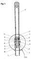
- the bollard shown in Fig. 1 consists of the following Individual parts: an embedding sleeve 1 to be embedded in concrete, a connector 2, a bollard top 3, two Clamping cones 4 and 5, a screw 6 and a nut (not shown), which in the one clamping cone, here e.g. 5, is used.
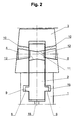
- the connecting piece 2 After anchoring the embedding sleeve 1, advantageously in concrete (not shown) shown individually in Figs. 5 and 6 is the connecting piece 2 via longitudinal grooves 7 (see Fig. 9 and 10) inserted in the embedding sleeve 1 and by rotation coupled by 90 ° like a bayonet. Cams 8 engage Connector 2 in a corresponding inner circumferential groove 9 of the Embedding sleeve 1.
- the configuration of the clamping cones 4, 5 is shown in FIGS. 3 and 4 shown.
- the screw-side clamping cone 4 has one Through hole 13 for the screw 6, during the nut-side clamping cone 5 in the described Embodiment a somewhat conical hexagon 14 for non-positive clamping of the nut matching screw 6 (not shown).
- the mother becomes so deep in that Hexagon socket 14 of the clamping cone 5 added that a Hexagon wrench of conventional type (not shown) yet be inserted into the hexagon socket 14 above the nut can counter to if the screw 6, the one Polygonal head, e.g. Triangular or square, with one appropriate special key (not shown) tightened becomes.
- a cover 16 can also be provided for the bollard is shown in Fig. 13 in side view and instead of Connector 2 and the bollard top 3 bayonet in the embedding sleeve 1 is locked when the bollard is not is needed and after loosening the screw 6 Bollard top 3 together with the connector 2 after turning back has been removed from the embedding sleeve 1 by 90 °.
- the lid 16 also has cams 17 for the bayonet catch in contrast to the cams 8 of the connector 2 in the Inner circumferential groove 9 of the embedding sleeve 1 hardly has any axial play to have.
- rainwater infiltration Embedding sleeve 1 is hollow and towards the connecting piece 2 Has axial bore 18.
- the connector 2 can also have a circumferential groove 19 as a predetermined breaking point.
Landscapes
- Architecture (AREA)
- Civil Engineering (AREA)
- Structural Engineering (AREA)
- Engineering & Computer Science (AREA)
- Refuge Islands, Traffic Blockers, Or Guard Fence (AREA)
- Led Devices (AREA)
- Road Signs Or Road Markings (AREA)
- Building Environments (AREA)
- Forms Removed On Construction Sites Or Auxiliary Members Thereof (AREA)
- Amplifiers (AREA)
- Light Receiving Elements (AREA)
- Rod-Shaped Construction Members (AREA)
- Recrystallisation Techniques (AREA)
- Thin Film Transistor (AREA)
- Medicines Containing Material From Animals Or Micro-Organisms (AREA)
- Pharmaceuticals Containing Other Organic And Inorganic Compounds (AREA)
Abstract
Description
- Fig. 1
- im Längsschnitt den fertig montierten Poller,
- Fig. 2
- in schematischer Einzeldarstellung das Verbindungsstück im Zusammenwirken mit dem Polleroberteil und der Einbetthülse vor dem Anziehen der Klemmkegel,
- Fig. 3
- perspektivisch den schraubenseitigen Klemmkegel,
- Fig. 4
- perspektivisch den mutterseitigen Klemmkegel,
- Fig. 5
- perspektivisch das Verbindungsstück,
- Fig. 6
- einen Längsschnitt des Verbindungsstücks,
- Fig. 7
- perspektivisch die Einbetthülse,
- Fig. 8
- einen Längsschnitt der Einbetthülse,
- Fig. 9
- einen weiteren Längsschnitt der Einbetthülse,
- Fig. 10
- einen Schnitt nach der Linie X-X in Fig. 11,
- Fig. 11
- perspektivisch das Polleroberteil,
- Fig. 12
- einen Längsschnitt des Polleroberteils nach Fig. 9,
- Fig. 13
- in Seitenansicht einen zugehörigen Deckel,
- Fig. 14
- einen Ausschnitt XIV aus Fig. 1 nach dem Anziehen der Klemmkegel und
- Fig. 15
- einen Schnitt nach der Linie XV-XV in Fig. 14.
Claims (5)
- Poller, bestehend aus einer in Beton erdbodenbündig einzubettenden Einbetthülse und einem mit dieser lösbar formschlüssig verbindbaren Polleroberteil, gekennzeichnet durch ein Verbindungsstück (2) zwischen Polleroberteil (3) und Einbetthülse (1), wobei das Verbindungsstück (2) mit der Einbetthülse (1) bajonettartig verbindbar ist und eine Querbohrung (11) aufweist, die an beiden Enden konisch erweitert ist und in diesen konischen Erweiterungen (12), die sich in einander gegenüberliegenden konischen Querbohrungen (10) des Polleroberteils (3) fortsetzen, je einen Klemmkegel (4 bzw. 5) aufnimmt, wobei diese Klemmkegel (4, 5) mittels einer mit einem entsprechenden Spezialschlüssel betätigbaren Schraube (6) das Verbindungsstück (2) in der Einbetthülse (1) innerhalb des Bajonettverschlusses (8, 9) kraftschlüssig festziehen und das Polleroberteil (3) gegen die Einbetthülse (1) verspannen.
- Poller nach Anspruch 1, dadurch gekennzeichnet, daß die Klemmkegel (4, 5) in den konischen Erweiterungen (12) der Querbohrung (11) des Verbindungsstücks (2) und in den konischen Querbohrungen (10) des Polieroberteils (3) mit entsprechendem Spiel sitzen, derart, daß sie beim Anziehen der Schraube (6) jeweils eine Keilwirkung zum Bewegen des Verbindungsstücks (2) nach oben und des Polleroberteils (3) nach unten ausüben.
- Poller nach Anspruch 1 oder 2, dadurch gekennzeichnet, daß das Verbindungsstück (2) einen Umfangseinstich (19) als Sollbruchstelle aufweist.
- Poller nach einem der vorangehenden Ansprüche, gekennzeichnet durch einen Deckel (16) zum Abdecken der Einbetthülse (1) bei abgenommenem Polleroberteil (3).
- Poller nach Anspruch 4, dadurch gekennzeichnet, daß der Deckel (16) mit der Einbetthülse (1) bajonettverschlußartig kuppelbar ist.
Priority Applications (1)
| Application Number | Priority Date | Filing Date | Title |
|---|---|---|---|
| SI200130624T SI1130167T1 (sl) | 2000-03-03 | 2001-03-05 | Priveznik |
Applications Claiming Priority (2)
| Application Number | Priority Date | Filing Date | Title |
|---|---|---|---|
| DE10010449A DE10010449C1 (de) | 2000-03-03 | 2000-03-03 | Poller |
| DE10010449 | 2000-03-03 |
Publications (3)
| Publication Number | Publication Date |
|---|---|
| EP1130167A2 true EP1130167A2 (de) | 2001-09-05 |
| EP1130167A3 EP1130167A3 (de) | 2003-10-22 |
| EP1130167B1 EP1130167B1 (de) | 2006-06-21 |
Family
ID=7633414
Family Applications (1)
| Application Number | Title | Priority Date | Filing Date |
|---|---|---|---|
| EP01105289A Expired - Lifetime EP1130167B1 (de) | 2000-03-03 | 2001-03-05 | Poller |
Country Status (7)
| Country | Link |
|---|---|
| EP (1) | EP1130167B1 (de) |
| AT (1) | ATE331085T1 (de) |
| DE (1) | DE10010449C1 (de) |
| DK (1) | DK1130167T3 (de) |
| ES (1) | ES2265368T3 (de) |
| PT (1) | PT1130167E (de) |
| SI (1) | SI1130167T1 (de) |
Families Citing this family (6)
| Publication number | Priority date | Publication date | Assignee | Title |
|---|---|---|---|---|
| FR2825740B1 (fr) * | 2001-06-08 | 2006-09-29 | Caravagna Jean Luc | Barriere de protection demontable |
| DE50112527D1 (de) * | 2001-10-09 | 2007-07-05 | Wemas Gmbh | Vorrichtung zur Befestigung einer Bake an einer Fussplatte |
| DE10326680B4 (de) * | 2003-06-13 | 2006-01-19 | Lutz Barich | Hochwasser-Schutzwand |
| DE102008045788A1 (de) | 2007-09-18 | 2009-03-26 | Lutz Barich | Befestigungselement zum Verbinden von öffentlichen Gegenständen wie Poller mit und ohne Beleuchtung, Straßenmobiliar, Straßenschilder, Spielplatzgeräte u. dgl. mit einer im Boden eingesetzten Einbetthülse |
| EP2039834B1 (de) | 2007-09-18 | 2012-11-14 | Lutz Barich | Befestigungselement zum Verbinden von öffentlichen Gegenständen wie Poller mit und ohne Beleuchtung, Strassenmobiliar, Strassenschilder, Spielplatzgeräte u. dgl. mit einer im Boden eingesetzten Einbetthülse |
| DE102021102067B4 (de) | 2021-01-29 | 2023-07-13 | Lutz Barich | Anordnung einer Vorrichtung auf einer Fläche oder einem Boden zur Bildung einer Abgrenzung bzw. Abtrennung von Flächen, Wegen o.dgl. |
Family Cites Families (4)
| Publication number | Priority date | Publication date | Assignee | Title |
|---|---|---|---|---|
| DE1845138U (de) * | 1961-10-24 | 1962-01-18 | Vdo Schindling | Haltevorrichtung fuer parkzeituhren. |
| DE2042640C3 (de) * | 1970-08-27 | 1979-11-29 | Erich 8151 Neukolbing Weichenrieder | Pfosten aus Kunststoff, insbesondere Straßenleitpfosten und Verfahren zu seiner Herstellung |
| DE3436091A1 (de) * | 1984-10-02 | 1986-04-10 | Ingeborg 7505 Ettlingen Jöckel | Halterung fuer poller |
| DE9210725U1 (de) * | 1992-08-11 | 1992-10-29 | Kuo, Mao-Te, Taipeh / T'ai-pei | Schnell austauschbarer Straßenschutz |
-
2000
- 2000-03-03 DE DE10010449A patent/DE10010449C1/de not_active Expired - Lifetime
-
2001
- 2001-03-05 PT PT01105289T patent/PT1130167E/pt unknown
- 2001-03-05 DK DK01105289T patent/DK1130167T3/da active
- 2001-03-05 AT AT01105289T patent/ATE331085T1/de active
- 2001-03-05 EP EP01105289A patent/EP1130167B1/de not_active Expired - Lifetime
- 2001-03-05 SI SI200130624T patent/SI1130167T1/sl unknown
- 2001-03-05 ES ES01105289T patent/ES2265368T3/es not_active Expired - Lifetime
Also Published As
| Publication number | Publication date |
|---|---|
| ATE331085T1 (de) | 2006-07-15 |
| DK1130167T3 (da) | 2006-10-30 |
| ES2265368T3 (es) | 2007-02-16 |
| EP1130167B1 (de) | 2006-06-21 |
| DE10010449C1 (de) | 2001-05-23 |
| EP1130167A3 (de) | 2003-10-22 |
| PT1130167E (pt) | 2006-10-31 |
| SI1130167T1 (sl) | 2007-02-28 |
Similar Documents
| Publication | Publication Date | Title |
|---|---|---|
| EP2085521B1 (de) | Erd- oder Felsanker mit einem Ankerzugglied aus einem oder mehreren Einzelementen mit korrosionsgeschützter Ankerkopfausbildung | |
| DE867909C (de) | Bolzen zum Befestigen von Gegenstaenden in Stein, Beton od. dgl. | |
| EP0801544A1 (de) | Verbindungsanordnung zwischen einem implantat und einem abutment | |
| EP0748422A1 (de) | Verbindungselement mit beidseitigem gewinde | |
| DE60031159T2 (de) | Abformkappen-system zur anwendung in der zahnimplantologie | |
| EP0243298A2 (de) | Bausatz für eine Schaftprothese | |
| DE202007015833U1 (de) | Schalungsanker | |
| DE10010449C1 (de) | Poller | |
| DE29500655U1 (de) | Bausatz aus verschiedenen Rundstäben zum Aufbau eines verkröpften Rundstab-Zugs | |
| EP2039834B1 (de) | Befestigungselement zum Verbinden von öffentlichen Gegenständen wie Poller mit und ohne Beleuchtung, Strassenmobiliar, Strassenschilder, Spielplatzgeräte u. dgl. mit einer im Boden eingesetzten Einbetthülse | |
| DE102005022335A1 (de) | Schalungsanker sowie Verfahren zum Verankern von Schalungselementen und Verfahren zum Lösen eines Schlalungsankers | |
| DE10326680B4 (de) | Hochwasser-Schutzwand | |
| DE19603682A1 (de) | Verankerungselement für Gestaltungs- und Nutzungsobjekte in öffentlichen Verkehrsraümen und Grünanlagen | |
| DE3910204A1 (de) | Gelaender | |
| AT407546B (de) | Spindeleinheit, insbesondere für den schalungsbau | |
| DE9303225U1 (de) | Befestigungsvorrichtung für Poller, Masten o.dgl. | |
| EP1847666A1 (de) | Ankervorrichtung zum Verbinden von Schalungstafeln | |
| EP3231941B1 (de) | Pfostensystem | |
| EP3913142B1 (de) | Stadtmobiliar | |
| EP3283694B1 (de) | Fundamentverankerung für arbeitsmaschine | |
| DE3403873A1 (de) | Vorrichtung zum befestigen eines huelsenfoermigen einbauteils an einer schalungsform | |
| DE29500727U1 (de) | Vorrichtung für eine Verbindung eines Zugelementes mit einem Armierungsstab eines Betonfertigteiles | |
| EP1004728A2 (de) | Anti-Panikschlosse | |
| DE917189C (de) | Leitungsverbinder fuer Hoch- und Mittelspannungsleitungen sowie fuer Ortsnetz- und Telephonleitungen | |
| DE19652898A1 (de) | Ankerhülse |
Legal Events
| Date | Code | Title | Description |
|---|---|---|---|
| PUAI | Public reference made under article 153(3) epc to a published international application that has entered the european phase |
Free format text: ORIGINAL CODE: 0009012 |
|
| AK | Designated contracting states |
Kind code of ref document: A2 Designated state(s): AT BE CH CY DE DK ES FI FR GB GR IE IT LI LU MC NL PT SE TR |
|
| AX | Request for extension of the european patent |
Free format text: AL;LT;LV;MK;RO;SI |
|
| PUAL | Search report despatched |
Free format text: ORIGINAL CODE: 0009013 |
|
| AK | Designated contracting states |
Kind code of ref document: A3 Designated state(s): AT BE CH CY DE DK ES FI FR GB GR IE IT LI LU MC NL PT SE TR |
|
| AX | Request for extension of the european patent |
Extension state: AL LT LV MK RO SI |
|
| 17P | Request for examination filed |
Effective date: 20040413 |
|
| AKX | Designation fees paid |
Designated state(s): AT BE CH DK ES FI FR GB GR IE IT LI LU NL PT SE TR |
|
| AXX | Extension fees paid |
Extension state: SI Payment date: 20040413 |
|
| REG | Reference to a national code |
Ref country code: DE Ref legal event code: 8566 |
|
| 17Q | First examination report despatched |
Effective date: 20040618 |
|
| GRAP | Despatch of communication of intention to grant a patent |
Free format text: ORIGINAL CODE: EPIDOSNIGR1 |
|
| GRAS | Grant fee paid |
Free format text: ORIGINAL CODE: EPIDOSNIGR3 |
|
| GRAA | (expected) grant |
Free format text: ORIGINAL CODE: 0009210 |
|
| AK | Designated contracting states |
Kind code of ref document: B1 Designated state(s): AT BE CH DK ES FI FR GB GR IE IT LI LU NL PT SE TR |
|
| AX | Request for extension of the european patent |
Extension state: SI |
|
| PG25 | Lapsed in a contracting state [announced via postgrant information from national office to epo] |
Ref country code: IT Free format text: LAPSE BECAUSE OF FAILURE TO SUBMIT A TRANSLATION OF THE DESCRIPTION OR TO PAY THE FEE WITHIN THE PRESCRIBED TIME-LIMIT;WARNING: LAPSES OF ITALIAN PATENTS WITH EFFECTIVE DATE BEFORE 2007 MAY HAVE OCCURRED AT ANY TIME BEFORE 2007. THE CORRECT EFFECTIVE DATE MAY BE DIFFERENT FROM THE ONE RECORDED. Effective date: 20060621 |
|
| REG | Reference to a national code |
Ref country code: GB Ref legal event code: FG4D Free format text: NOT ENGLISH |
|
| REG | Reference to a national code |
Ref country code: CH Ref legal event code: EP |
|
| REG | Reference to a national code |
Ref country code: IE Ref legal event code: FG4D Free format text: LANGUAGE OF EP DOCUMENT: GERMAN |
|
| REG | Reference to a national code |
Ref country code: CH Ref legal event code: NV Representative=s name: PA ALDO ROEMPLER |
|
| GBT | Gb: translation of ep patent filed (gb section 77(6)(a)/1977) |
Effective date: 20060912 |
|
| REG | Reference to a national code |
Ref country code: SE Ref legal event code: TRGR |
|
| REG | Reference to a national code |
Ref country code: DK Ref legal event code: T3 |
|
| REG | Reference to a national code |
Ref country code: PT Ref legal event code: SC4A Effective date: 20060810 |
|
| REG | Reference to a national code |
Ref country code: GR Ref legal event code: EP Ref document number: 20060403147 Country of ref document: GR |
|
| ET | Fr: translation filed | ||
| REG | Reference to a national code |
Ref country code: ES Ref legal event code: FG2A Ref document number: 2265368 Country of ref document: ES Kind code of ref document: T3 |
|
| PLBE | No opposition filed within time limit |
Free format text: ORIGINAL CODE: 0009261 |
|
| STAA | Information on the status of an ep patent application or granted ep patent |
Free format text: STATUS: NO OPPOSITION FILED WITHIN TIME LIMIT |
|
| 26N | No opposition filed |
Effective date: 20070322 |
|
| REG | Reference to a national code |
Ref country code: CH Ref legal event code: PCAR Free format text: ALDO ROEMPLER PATENTANWALT;BRENDENWEG 11 POSTFACH 154;9424 RHEINECK (CH) |
|
| PG25 | Lapsed in a contracting state [announced via postgrant information from national office to epo] |
Ref country code: TR Free format text: LAPSE BECAUSE OF FAILURE TO SUBMIT A TRANSLATION OF THE DESCRIPTION OR TO PAY THE FEE WITHIN THE PRESCRIBED TIME-LIMIT Effective date: 20060621 |
|
| REG | Reference to a national code |
Ref country code: FR Ref legal event code: PLFP Year of fee payment: 16 |
|
| REG | Reference to a national code |
Ref country code: FR Ref legal event code: PLFP Year of fee payment: 17 |
|
| REG | Reference to a national code |
Ref country code: FR Ref legal event code: PLFP Year of fee payment: 18 |
|
| PGFP | Annual fee paid to national office [announced via postgrant information from national office to epo] |
Ref country code: FI Payment date: 20190319 Year of fee payment: 19 Ref country code: FR Payment date: 20190326 Year of fee payment: 19 Ref country code: LU Payment date: 20190321 Year of fee payment: 19 Ref country code: GB Payment date: 20190325 Year of fee payment: 19 Ref country code: CH Payment date: 20190325 Year of fee payment: 19 Ref country code: IT Payment date: 20190321 Year of fee payment: 19 Ref country code: IE Payment date: 20190326 Year of fee payment: 19 |
|
| PGFP | Annual fee paid to national office [announced via postgrant information from national office to epo] |
Ref country code: NL Payment date: 20190321 Year of fee payment: 19 Ref country code: BE Payment date: 20190321 Year of fee payment: 19 Ref country code: SE Payment date: 20190325 Year of fee payment: 19 Ref country code: AT Payment date: 20190319 Year of fee payment: 19 Ref country code: DK Payment date: 20190325 Year of fee payment: 19 Ref country code: GR Payment date: 20190319 Year of fee payment: 19 |
|
| PGFP | Annual fee paid to national office [announced via postgrant information from national office to epo] |
Ref country code: ES Payment date: 20190424 Year of fee payment: 19 |
|
| PGFP | Annual fee paid to national office [announced via postgrant information from national office to epo] |
Ref country code: PT Payment date: 20200228 Year of fee payment: 20 |
|
| REG | Reference to a national code |
Ref country code: FI Ref legal event code: MAE |
|
| PG25 | Lapsed in a contracting state [announced via postgrant information from national office to epo] |
Ref country code: FI Free format text: LAPSE BECAUSE OF NON-PAYMENT OF DUE FEES Effective date: 20200305 |
|
| REG | Reference to a national code |
Ref country code: CH Ref legal event code: PL |
|
| REG | Reference to a national code |
Ref country code: DK Ref legal event code: EBP Effective date: 20200331 |
|
| REG | Reference to a national code |
Ref country code: NL Ref legal event code: MM Effective date: 20200401 |
|
| REG | Reference to a national code |
Ref country code: AT Ref legal event code: MM01 Ref document number: 331085 Country of ref document: AT Kind code of ref document: T Effective date: 20200305 |
|
| REG | Reference to a national code |
Ref country code: BE Ref legal event code: MM Effective date: 20200331 |
|
| PG25 | Lapsed in a contracting state [announced via postgrant information from national office to epo] |
Ref country code: NL Free format text: LAPSE BECAUSE OF NON-PAYMENT OF DUE FEES Effective date: 20200401 Ref country code: LU Free format text: LAPSE BECAUSE OF NON-PAYMENT OF DUE FEES Effective date: 20200305 |
|
| PG25 | Lapsed in a contracting state [announced via postgrant information from national office to epo] |
Ref country code: LI Free format text: LAPSE BECAUSE OF NON-PAYMENT OF DUE FEES Effective date: 20200331 Ref country code: GR Free format text: LAPSE BECAUSE OF NON-PAYMENT OF DUE FEES Effective date: 20201008 Ref country code: AT Free format text: LAPSE BECAUSE OF NON-PAYMENT OF DUE FEES Effective date: 20200305 Ref country code: IE Free format text: LAPSE BECAUSE OF NON-PAYMENT OF DUE FEES Effective date: 20200305 Ref country code: FR Free format text: LAPSE BECAUSE OF NON-PAYMENT OF DUE FEES Effective date: 20200331 Ref country code: SE Free format text: LAPSE BECAUSE OF NON-PAYMENT OF DUE FEES Effective date: 20200306 Ref country code: CH Free format text: LAPSE BECAUSE OF NON-PAYMENT OF DUE FEES Effective date: 20200331 |
|
| PG25 | Lapsed in a contracting state [announced via postgrant information from national office to epo] |
Ref country code: BE Free format text: LAPSE BECAUSE OF NON-PAYMENT OF DUE FEES Effective date: 20200331 |
|
| GBPC | Gb: european patent ceased through non-payment of renewal fee |
Effective date: 20200305 |
|
| PG25 | Lapsed in a contracting state [announced via postgrant information from national office to epo] |
Ref country code: GB Free format text: LAPSE BECAUSE OF NON-PAYMENT OF DUE FEES Effective date: 20200305 Ref country code: PT Free format text: LAPSE BECAUSE OF EXPIRATION OF PROTECTION Effective date: 20210315 Ref country code: DK Free format text: LAPSE BECAUSE OF NON-PAYMENT OF DUE FEES Effective date: 20200331 |
|
| REG | Reference to a national code |
Ref country code: ES Ref legal event code: FD2A Effective date: 20210726 |
|
| PG25 | Lapsed in a contracting state [announced via postgrant information from national office to epo] |
Ref country code: IT Free format text: LAPSE BECAUSE OF NON-PAYMENT OF DUE FEES Effective date: 20200305 |
|
| PG25 | Lapsed in a contracting state [announced via postgrant information from national office to epo] |
Ref country code: ES Free format text: LAPSE BECAUSE OF NON-PAYMENT OF DUE FEES Effective date: 20200306 |