EP1130197B1 - Schliessblech mit Flüstereffekt - Google Patents
Schliessblech mit Flüstereffekt Download PDFInfo
- Publication number
- EP1130197B1 EP1130197B1 EP99124493A EP99124493A EP1130197B1 EP 1130197 B1 EP1130197 B1 EP 1130197B1 EP 99124493 A EP99124493 A EP 99124493A EP 99124493 A EP99124493 A EP 99124493A EP 1130197 B1 EP1130197 B1 EP 1130197B1
- Authority
- EP
- European Patent Office
- Prior art keywords
- lock
- door
- receiving cavity
- bolt
- spring
- Prior art date
- Legal status (The legal status is an assumption and is not a legal conclusion. Google has not performed a legal analysis and makes no representation as to the accuracy of the status listed.)
- Expired - Lifetime
Links
Images



Classifications
-
- E—FIXED CONSTRUCTIONS
- E05—LOCKS; KEYS; WINDOW OR DOOR FITTINGS; SAFES
- E05B—LOCKS; ACCESSORIES THEREFOR; HANDCUFFS
- E05B15/00—Other details of locks; Parts for engagement by bolts of fastening devices
- E05B15/02—Striking-plates; Keepers; Bolt staples; Escutcheons
- E05B15/0205—Striking-plates, keepers, staples
- E05B15/022—Striking-plates, keepers, staples movable, resilient or yieldable
- E05B15/0225—Resilient block type, e.g. made from rubber
-
- E—FIXED CONSTRUCTIONS
- E05—LOCKS; KEYS; WINDOW OR DOOR FITTINGS; SAFES
- E05B—LOCKS; ACCESSORIES THEREFOR; HANDCUFFS
- E05B17/00—Accessories in connection with locks
- E05B17/0045—Silencing devices; Noise reduction
Definitions
- the present invention relates to a striking plate with a whisper effect.
- Strike plates according to the invention can be related to room or front doors as well any other doors.
- Striking plates are known from the prior art in various forms.
- Known striking plates have in particular a latch receiving cavity or a bolt receiving cavity for receiving the lock latch or the lock bolt a door lock. They are screwed into the rebate cladding the door frame of a door mounted.
- a separate striking plate is not required, but it a locking area integrated in one piece into the door frame is provided, which the Has latch receiving cavity or the bolt receiving cavity.
- the function the closing area of an integral door frame is the same as that a separate striking plate.
- the annoying impact sound occurs even when a door from Hand is closed without pressing the doorknob far enough down and thereby pull the lock latch sufficiently far into the lock.
- the lock latch strikes the striking plate, is then pressed into the lock and finally jumps due to their spring preload in the Strike plate cavity of the striking plate.
- the insert has a trap receiving cavity for receiving a Lock latch of a lock mounted in a door. Furthermore is one Stop edge provided in the door closing direction (in Fig. 3a from right to left) is arranged in front of the latch receiving cavity and to which the lock latch thus strikes with the formation of a stop sound when the door is in Door closing direction falls.
- the trap receiving cavity and the stop edge Extensive use is in the interest of good noise insulation made of plastic manufactured. The noise insulation with separate striking plates enables known use not.
- a similar insert in the form of a cleaning box is from DE-A-22 26 640 known.
- the plastic cleaning box has a stop edge for the Lock latch that reduces noise when the door is closed.
- a Noise reduction with strikers to be installed separately is also included this use is not possible.
- the striking plate for door frames in particular has a latch receiving cavity to hold a lock latch made of a certain material a lock mounted in a door, whereby in the door closing direction there is a stop edge in front of the trap receiving cavity which strikes the lock latch with the formation of a stop sound when the Door closes in the door closing direction, and the stop edge is designed as an insert is and consists of a material or is coated with a material, which dampens the impact sound with regard to the material of the lock latch.
- the choice of the material of the stop edge or the material of the The stop edge coating depends on the material of the lock latch. To note that the damping of the impact sound in the sense of the present Invention can also be achieved if the lock latch and stop edge or Edge coating are made of the same material. When choosing this Material is only important to ensure that when two parts hit each other no or no significant impact sound is produced from this material.
- lock latches made of metallic materials Plastic as material for the stop edge or the stop edge coating selected.
- the material pairings plastic / plastic are also conceivable as well as plastic / metal, the lock latch material being mentioned first.
- the stop edge is used only as an insert train.
- the insert can either be clipped into the striking plate with a force fit and / or with the aid of other fastening means, for example screws be attached to the striking plate.
- Conventional striking plates, which according to the invention are to be converted, are in the area of their stop edges prepare enough space for the insertion of the as a stop edge functioning insert is present.
- the insert not only has the stop edge itself, but also additionally the trap receiving cavity.
- Such an application can be releasably attached to a cover, which with a corresponding Trap receptacle opening is provided, so the stop edge comes in Latch receiving opening to lie that the lock latch only the stop edge and cannot touch the cover part itself.
- the cover part can be the latch receiving area of the latch receiving area be conventional, i.e. a latch receiving cavity not designed as an insert exhibit.
- the cover part itself can be made of a metallic Material, for example aluminum, made of plastic or a material Carbon fiber base exist. In particular, are nylon, polyamide, glass fiber or carbon fiber reinforced plastics conceivable.
- the surfaces of the cover can be galvanically treated, powder-coated or painted.
- the present invention has the advantage of a kind of shock absorber effect with himself.
- This shock absorber effect is caused by the material combination insert / cover part causes.
- the insert consists of a non-metallic one Material, such as plastic, and the cover made of metal dampen the use the impact of the lock latch against the cover part acting on the stop edge and thus compared to the entire door frame.
- the stop edge and the trap receiving cavity are advantageous not only the stop edge and the trap receiving cavity as an insert, but also the bolt receiving cavity to be provided together with a further stop edge on the insert.
- the additional stop edge made of the same material as that of the trap receiving cavity assigned stop edge or is coated with the same material.
- the cover part has a bolt receiving opening, in which the further stop edge when attaching the insert to the cover part comes to rest.
- the stop edge and / or the further stop edge preferably has an in about a quarter-cylindrical surface. This ensures an unhindered Sliding movement of the slant of the lock latch along the stop edge.
- the surface of the stop edge can also take a shape which one corresponds to a circular cylindrical surface area, which is less than a quarter of a Full circle extends. Other geometries, such as one, are also conceivable chamfered stop edge.
- the striking plate according to the invention can also be used Can be attached to the door frame using additional securing means.
- a reinforcing plate preferably made of metal connected, for example screwed, which are also on the door frame is attached. This attachment is also preferably carried out by screwing.
- Another way to prevent burglary is to use the reinforcement plate to be arranged on the cover part.
- the reinforcing plate can be integral or provided in one piece on the cover part or with the aid of fastening means, for example screws, to be connected to this.
- Reinforcing plate can also have several strip-shaped securing fingers on the cover part be provided, which at their connection points with the cover part can be cranked so that they are in the door closing direction in front of the plane of the actual cover part.
- the reinforcement plate or are the locking fingers integrally connected to the cover part so they consist of the same Material like this. If they are provided as separate parts, they must do not consist of the same material as the cover part.
- metal comes as a material for the reinforcement plate or the locking fingers also plastic in Question.
- the latch and / or bolt receiving cavity are in the door closing direction bounded at the front by a latch and / or a bolt receptacle wall, which is at least partially inclined so that the trap and / or the bolt receiving cavity at least in the latch or bolt entry direction partially rejuvenated.
- the latch and / or the bolt receiving cavity can be in the latch or bolt entry direction be bounded by a bottom wall. This prevents that from through the latch receiving cavity or the latch receiving cavity Rebate cladding of the door frame can be viewed.
- the bottom wall is perforated along its circumference in such a way that it can be broken out by hand. The lock bolt can then move accordingly move far in the bolt entry direction and thereby the bolt receiving cavity enforce completely.
- the bottom walls are also conceivable omit the latch and / or bolt receiving cavity from the outset.
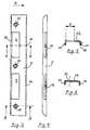
- Fig. 1 shows an inventive, separate striking plate 1 in an exploded view.
- the striking plate 1 comprises the metal cover 5 and the insert 4, which is an injection molded part made of plastic.
- the invention Whisper effect is thus in the embodiment shown with regard to such lock latch materials achieved which none when hitting plastic or generate only a small impact sound. This applies, for example, to Lock latches made of metal.
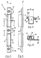
- the cover part 5 an elongated rectangular shape and a U-shaped cross section with proportionate short U-legs 10 and 21. It was manufactured using the deep-drawing process.
- the latch receiving opening 6 and the bolt receiving opening 9 have the same rectangular shape and are arranged in such a way that Fig. 1 and 5 left transition radius between the U-web 22 and the U-leg 21 run in or include this.
- Fig. 1 there are also three Recognized countersunk holes 23 through which fastening screws, not shown reach through to fasten the striking plate 1 to the door frame.
- 4 and 5 are two bores 11 and 12 provided in the U-leg 10 to recognize which are used to hold the insert 4 securely in the U-profile.
- the insert 4 can be seen in FIGS. 1 and 7 to 12. It is symmetrical to that 7 shown section line of the section D-D. The same applies to the cover part 5 with respect to a corresponding cutting line through the middle Hole 23.
- the insert 4 includes the trap receiving cavity 2 and the Bolt receiving cavity 7, both of which are cuboid.
- the in Fig. 11 shown bottom walls 19 and 20 of the trap receiving cavity 2 and of the bolt receiving ear space 7 can be omitted or along if necessary their respective circumference be perforated to break them out if necessary to be able to.
- Fig. 1 the stop edge 3 can be seen, which in the door closing direction according to arrow R is in front of the trap receiving cavity 2. Furthermore is the further Stop edge 8 shown, which also in the door closing direction R in front of the bolt receiving cavity 7 lies.
- the stop edge 3 surrounds together with the peripheral edges 24, 25 and 26 the rectangular opening of the trap receiving cavity 2.
- the peripheral edges 24, 25 and 26 and the stop edge 3 are in the Fig. 1 above the plane E, which is located in Figs. 8,9 and 12 Die Level E falls when the insert 4 is inserted into the cover part 5 at the level of inner or in FIGS. 5 and 6 lower surface of the U-web 22 together.
- peripheral edges 24, 25 and 26 protrude beyond the plane E corresponds essentially to the material thickness of the U-web 22 of the cover part 5. Due to the symmetry of the insert 4, the same geometrical relationships apply to the peripheral edges 27, 28 and 29 of the bolt receiving cavity 7.
- peripheral edges 24, 25, 26 and 27, 28, 29 in the manner described are raised compared to level E and the peripheral edges 25, 26 and 28, 29 in the If the surfaces of the stop edges 3 or 8 pass over, the peripheral edges fit and stop edges in the manner shown in Fig. 2 to the outer contour of the cover part 5 when the insert 4 is inserted into the U-profile of the cover part 5.
- the circumferential edges 24 to 29 and the sit Stop edges 3 and 8 flush in the latch or bolt receiving opening 6 or 9, so that they form part of the outer contour of the striking plate according to the invention 1 form.
- the striking plate 1 When the striking plate 1 is assembled according to FIG. 2, it lies below the Stop edge 3 and the contact surface 30 shown in FIG. 9 on the one in FIG. 3 marked counter surface 31 of the cover part 5.
- the dimension e shown in FIG. 9 can be a be chosen slightly larger than the dimension b shown in FIG. 5. This will achieved that the insert 4 non-positively in the latch or bolt receiving opening 6 or 9 is held.
- the stop edge 3 has a quarter circle Cross section on, so that the surface of the stop edge 3 quarter-cylindrical is shaped.
- the radii of the quarter-cylindrical surface are preferably in Range from 1 mm to 10 mm.
- the angle of inclination ⁇ is the trap receiving cavity wall 18 recognizable.
- the width of the trap receiving cavity 2 tapers in Trap entry direction from top to bottom.
- Lock latch in the trap receiving cavity 2 can the trap receiving cavity wall over part of their height or, if necessary, over their entire height run inclined.
- the inclination ⁇ means that the lock latch also which are within a certain tolerance, still in the Trap receiving cavity 2 engages and can keep the door closed. With increasing Door leaf warping is always the front edge of the lock latch in Fig. 9 further up on the inclined trap receiving cavity wall 18.
- the insert 4 In the area of the two ends and between the trap receiving cavity 2 and the bolt receiving cavity 7 has the insert 4 substantially cuboid Wells 34, in each of which a cylindrical casting eye 35 with countersunk through hole 36 is located as shown in FIGS. 1 and 10. Fastening screws, not shown, run through the through bores 36 for fastening the striking plate 1 to the door frame. As shown in particular in FIGS. 11 and 12, the insert 4 has on it Underside underneath the depressions 34, three attachment lugs 15, 16 and 17 on. These protrude in the door closing direction R, i.e. 11 to the left in FIG in the same direction as the holding mandrels 13, 14, from the insert 4.
Landscapes
- Lock And Its Accessories (AREA)
- Clamps And Clips (AREA)
- Orthopedics, Nursing, And Contraception (AREA)
- Securing Of Glass Panes Or The Like (AREA)
- Medicines Containing Material From Animals Or Micro-Organisms (AREA)
- Connection Of Plates (AREA)
Description
- Fig. 1
- eine perspektivische Explosionsdarstellung eines erfindungsgemäßen Schließblechs, umfassend das Abdeckteil und den Einsatz;
- Fig. 2
- eine perspektivische Ansicht eines erfindungsgemäßen Schließblechs in zusammengebautem Zustand;
- Fig. 3
- eine Ansicht des Abdeckteils gemäß Fig. 1 von vorne;
- Fig. 4
- eine Ansicht des Abdeckteils gemäß Fig. 3 von links;
- Fig. 5
- den Schnitt A-A in Fig. 3;
- Fig. 6
- den Schnitt B-B in Fig. 3;
- Fig. 7
- eine Ansicht des Einsatzes gemäß Fig. 1 von vorne;
- Fig. 8
- eine Ansicht des Einsatzes gemäß Fig. 7 von links;
- Fig. 9
- den Schnitt C-C in Fig. 7;
- Fig. 10
- den Schnitt D-D in Fig. 7;
- Fig. 11
- eine Ansicht des Einsatzes gemäß Fig. 1 von hinten; und
- Fig. 12
- eine Ansicht des Einsatzes gemäß Fig. 11 von links.
Claims (8)
- Schließblech für Türzargen miteinem Fallenaufnahmehohlraum (2) zur Aufnahme einer Schloßfalle eines in einer Tür montierten Schlosses,einer Anschlagkante (3), die in Türschließrichtung (R) vor dem Fallenaufnahmehohlraum (2) angeordnet ist und an welche die Schloßfalle unter Entstehung eines Anschlagschalls anschlägt, wenn die Tür in Türschließrichtung (R) zufällt,einem Einsatz (4), der die Anschlagkante (3) bildet und aus einem Werkstoff besteht oder mit einem Werkstoff beschichtet ist, welcher den Anschlagschall dämpft, wobei der Einsatz (4) neben der Anschlagkante (3) auch den Fallenaufnahmehohlraum (2) umfaßt, undeinem Abdeckteil (5) mit einem Fallenaufnahmedurchbruch (6), wobei der Einsatz (4) derart lösbar an dem Abdeckteil (5) befestigbar ist, dass die Anschlagkante (3) in dem Fallenaufnahmedurchbruch (6) zu liegen kommt.
- Schließblech nach Anspruch 1,
dadurch gekennzeichnet, dass
ein Riegelaufnahmehohlraum (7) zur Aufnahme eines Schloßriegels und eine weitere Anschlagkante (8) als Bestandteile des Einsatzes (4) vorgesehen sind, wobei die weitere Anschlagkante (8) aus dem Werkstoff besteht oder mit dem Werkstoff beschichtet ist und das Abdeckteil (5) einen Riegelaufnahmedurchbruch (9) aufweist, in welchem die weitere Anschlagkante (8) zu liegen kommt. - Schließblech nach Anspruch 1 oder 2,
dadurch gekennzeichnet, dass
das Abdeckteil (5) einen im wesentlichen U-förmigen Querschnitt aufweist und in dem in Türschließrichtung (R) hinten liegenden U-Schenkel (10) wenigstens ein Loch (11,12) vorgesehen ist, wobei der Einsatz (4) wenigstens einen Haltedorn (13,14) aufweist, der in das Loch (11, 12) eingreift. - Schließblech nach einem der vorangehenden Ansprüche,
dadurch gekennzeichnet, dass
der Einsatz (4) wenigstens einen Befestigungsansatz (15,16,17) zur Befestigung einer Verstärkungsplatte aufweist, mittels welcher das Schließblech (1) an der Türzarge gesichert wird. - Schließblech nach einem der vorangehenden Ansprüche,
dadurch gekennzeichnet, dass
das Abdeckteil (5) an seiner in Türöffnungsrichtung (R) hinten liegenden Seite wenigstens einen Sicherungsfinger aufweist, mittels welchem das Schließblech (1) an der Türzarge gesichert wird. - Schließblech nach einem der vorangehenden Ansprüche,
dadurch gekennzeichnet, dass
die Anschlagkante (3) und/oder die weitere Anschlagkante (8) eine im wesentlichen viertelzylindrische Oberfläche aufweist bzw. aufweisen. - Schließblech nach einem der vorangehenden Ansprüche,
dadurch gekennzeichnet, dass
der Fallen- (2) und/oder der Riegelaufnahmehohlraum (7) in Türschließrichtung (R) nach vorne von einer Fallen- (18) und/oder einer Riegelaufnahmehohlraumwandung begrenzt wird, welche zumindest teilweise derart geneigt (α) verläuft, dass sich der Fallen- (2) und/oder der Riegelaufnahmehohlraum (7) in Fallen- bzw. Riegeleintrittsrichtung zumindest teilweise verjüngt. - Schließblech nach einem der vorangehenden Ansprüche,
dadurch gekennzeichnet, dass
der Fallen- (2) und/oder der Riegelaufnahmehohlraum (7) in Fallen- bzw. Riegeleintrittsrichtung von einer Bodenwandung (19,20) begrenzt wird, welche derart entlang ihres Umfangs perforiert ist, dass sie von Hand herausbrechbar ist.
Priority Applications (4)
| Application Number | Priority Date | Filing Date | Title |
|---|---|---|---|
| EP99124493A EP1130197B1 (de) | 1999-12-08 | 1999-12-08 | Schliessblech mit Flüstereffekt |
| DK99124493T DK1130197T3 (da) | 1999-12-08 | 1999-12-08 | Låseblik med støjreducerende virkning |
| DE59905500T DE59905500D1 (de) | 1999-12-08 | 1999-12-08 | Schliessblech mit Flüstereffekt |
| AT99124493T ATE239845T1 (de) | 1999-12-08 | 1999-12-08 | Schliessblech mit flüstereffekt |
Applications Claiming Priority (1)
| Application Number | Priority Date | Filing Date | Title |
|---|---|---|---|
| EP99124493A EP1130197B1 (de) | 1999-12-08 | 1999-12-08 | Schliessblech mit Flüstereffekt |
Publications (2)
| Publication Number | Publication Date |
|---|---|
| EP1130197A1 EP1130197A1 (de) | 2001-09-05 |
| EP1130197B1 true EP1130197B1 (de) | 2003-05-07 |
Family
ID=8239555
Family Applications (1)
| Application Number | Title | Priority Date | Filing Date |
|---|---|---|---|
| EP99124493A Expired - Lifetime EP1130197B1 (de) | 1999-12-08 | 1999-12-08 | Schliessblech mit Flüstereffekt |
Country Status (4)
| Country | Link |
|---|---|
| EP (1) | EP1130197B1 (de) |
| AT (1) | ATE239845T1 (de) |
| DE (1) | DE59905500D1 (de) |
| DK (1) | DK1130197T3 (de) |
Cited By (2)
| Publication number | Priority date | Publication date | Assignee | Title |
|---|---|---|---|---|
| DE10328330A1 (de) * | 2003-06-24 | 2005-01-20 | Baugruppentechnik Pollmeier Gmbh | Schließblech mit Federungsabschnitt |
| CN108474216A (zh) * | 2016-01-11 | 2018-08-31 | 普兰特Gdz股份公司 | 锁紧槽 |
Families Citing this family (10)
| Publication number | Priority date | Publication date | Assignee | Title |
|---|---|---|---|---|
| DE102005012856A1 (de) * | 2005-03-17 | 2006-09-28 | Carl Fuhr Gmbh & Co. Kg | Schliessleistenaggregat für ein Türschloss |
| DE102006037476A1 (de) * | 2006-08-10 | 2008-02-14 | H & K Teckentrup Kg | Stahlzarge für eine Drehtür |
| DE202006018772U1 (de) * | 2006-12-12 | 2008-04-17 | Sylid Systemlogistik Und Industriedienstleistung Gmbh | Schließleiste |
| DE102008032072A1 (de) | 2008-07-08 | 2010-01-14 | Assa Abloy Sicherheitstechnik Gmbh | Schließblech und Stulp und deren Verwendung |
| PL2281984T3 (pl) * | 2009-06-29 | 2017-03-31 | Vkr Holding A/S | Zespół zamka |
| CH702814A1 (de) * | 2010-03-02 | 2011-09-15 | Planet Gdz Ag | Verriegelungsmulde. |
| DE202013102260U1 (de) * | 2013-05-23 | 2014-08-25 | T + T Teching Gbr ( Vertretungsberechtigter Gesellschafter Dr. Andreas Teckentrup, 33378 Rheda-Wiedenbrück) | Aufnahmetasche für ein Schließelement eines Türschlosses, Türzarge und Tür |
| US11377875B2 (en) * | 2016-09-19 | 2022-07-05 | Level Home, Inc. | Deadbolt position sensing |
| US11462062B1 (en) * | 2019-07-19 | 2022-10-04 | Alarm.Com Incorporated | Power connection for smart lock devices |
| CN111140099A (zh) * | 2019-12-26 | 2020-05-12 | 湖南汉坤建筑安保器材有限公司 | 一种具有防刮伤功能的防盗门安全锁片 |
Family Cites Families (3)
| Publication number | Priority date | Publication date | Assignee | Title |
|---|---|---|---|---|
| DE2226640A1 (de) * | 1972-05-31 | 1973-12-13 | Hoermann Kg | Zargen-putzkasten |
| DE2445834A1 (de) * | 1974-09-25 | 1976-04-15 | Greschbach Stahlbau | Schliesschlitzausbildung in einer tuerzarge |
| CH663818A5 (en) * | 1984-07-06 | 1988-01-15 | Geilinger Ag | Protective casing for steel door bolt - is plastics moulding with open edge shaped to give snap action connection with door |
-
1999
- 1999-12-08 AT AT99124493T patent/ATE239845T1/de not_active IP Right Cessation
- 1999-12-08 DE DE59905500T patent/DE59905500D1/de not_active Expired - Lifetime
- 1999-12-08 EP EP99124493A patent/EP1130197B1/de not_active Expired - Lifetime
- 1999-12-08 DK DK99124493T patent/DK1130197T3/da active
Cited By (2)
| Publication number | Priority date | Publication date | Assignee | Title |
|---|---|---|---|---|
| DE10328330A1 (de) * | 2003-06-24 | 2005-01-20 | Baugruppentechnik Pollmeier Gmbh | Schließblech mit Federungsabschnitt |
| CN108474216A (zh) * | 2016-01-11 | 2018-08-31 | 普兰特Gdz股份公司 | 锁紧槽 |
Also Published As
| Publication number | Publication date |
|---|---|
| EP1130197A1 (de) | 2001-09-05 |
| ATE239845T1 (de) | 2003-05-15 |
| DE59905500D1 (de) | 2003-06-12 |
| DK1130197T3 (da) | 2003-07-28 |
Similar Documents
| Publication | Publication Date | Title |
|---|---|---|
| EP1130197A1 (de) | Schliessblech mit Flüstereffekt sowie Einsatz für integrale Türzargen mit Flüstereffekt | |
| EP2796645B1 (de) | Riegelschloss eines Möbels | |
| EP1485555B1 (de) | Beschlagsgarnitur | |
| DE102007017453A1 (de) | Drehöffnungsbegrenzungsvorrichtung für einen Flügel eines Fensters oder dergleichen | |
| EP2113624B1 (de) | Tür- oder Fenstersicherungsvorrichtung | |
| EP0681079A1 (de) | Fenster- oder Türrahmen mit darauf befestigtem Schliessblech und darin eingreifendem Schliessbolzen | |
| DE19522220C2 (de) | Schließvorrichtung | |
| DE19511109B4 (de) | Objektschutztür | |
| DE60208306T2 (de) | Schloss mit Sicherheitsblock gegen Einbruch | |
| DE69810009T2 (de) | Verriegelungsvorrichtung für einen Schiebeflügel | |
| DE102012103277A1 (de) | Einbruchshemmende Verriegelungseinheit | |
| EP3366873B1 (de) | Fenster-/türsicherung | |
| EP0886022B1 (de) | Türverschluss | |
| DE4227448C2 (de) | Schloßsicherung für Sicherheitsschließ-Zylinder | |
| EP2910713B1 (de) | Einsteckschloss | |
| DE19507481C1 (de) | Abschließbarer Fenstergriff | |
| EP0500125B1 (de) | Verschluss für Fenster oder Türen | |
| EP1255005B1 (de) | Riegelbeschlag | |
| EP1813754B1 (de) | Obertürschliesser | |
| EP1498563B1 (de) | Spaltlüftungsvorrichtung | |
| DE10151193B4 (de) | Garagentür- oder -tor | |
| DE9411842U1 (de) | Hakenschwenkriegelschloß, insbesondere zur Verwendung als Einsteck-Rohrprofilschloß | |
| EP3553260A1 (de) | Falleneinsatz mit tagstellung zur bedingten freigabe einer schlossfalle eines türschlossmechanismus | |
| DE29805276U1 (de) | Vorrichtung mit einer Einbruchsicherung zum Verschließen einer Öffnung | |
| DE20316622U1 (de) | Band für Türen, Fenster o.dgl. |
Legal Events
| Date | Code | Title | Description |
|---|---|---|---|
| PUAI | Public reference made under article 153(3) epc to a published international application that has entered the european phase |
Free format text: ORIGINAL CODE: 0009012 |
|
| AK | Designated contracting states |
Kind code of ref document: A1 Designated state(s): AT BE CH CY DE DK ES FI FR GB GR IE IT LI LU MC NL PT SE |
|
| AX | Request for extension of the european patent |
Free format text: AL;LT;LV;MK;RO;SI |
|
| 17P | Request for examination filed |
Effective date: 20010827 |
|
| AKX | Designation fees paid |
Free format text: AT BE CH CY DE DK ES FI FR GB GR IE IT LI LU MC NL PT SE |
|
| 17Q | First examination report despatched |
Effective date: 20020607 |
|
| GRAH | Despatch of communication of intention to grant a patent |
Free format text: ORIGINAL CODE: EPIDOS IGRA |
|
| RTI1 | Title (correction) |
Free format text: STRIKER WITH NOISE REDUCING EFFECT |
|
| GRAH | Despatch of communication of intention to grant a patent |
Free format text: ORIGINAL CODE: EPIDOS IGRA |
|
| GRAA | (expected) grant |
Free format text: ORIGINAL CODE: 0009210 |
|
| AK | Designated contracting states |
Designated state(s): AT BE CH CY DE DK ES FI FR GB GR IE IT LI LU MC NL PT SE |
|
| PG25 | Lapsed in a contracting state [announced via postgrant information from national office to epo] |
Ref country code: IT Free format text: LAPSE BECAUSE OF FAILURE TO SUBMIT A TRANSLATION OF THE DESCRIPTION OR TO PAY THE FEE WITHIN THE PRESCRIBED TIME-LIMIT;WARNING: LAPSES OF ITALIAN PATENTS WITH EFFECTIVE DATE BEFORE 2007 MAY HAVE OCCURRED AT ANY TIME BEFORE 2007. THE CORRECT EFFECTIVE DATE MAY BE DIFFERENT FROM THE ONE RECORDED. Effective date: 20030507 Ref country code: IE Free format text: LAPSE BECAUSE OF NON-PAYMENT OF DUE FEES Effective date: 20030507 Ref country code: GB Free format text: LAPSE BECAUSE OF FAILURE TO SUBMIT A TRANSLATION OF THE DESCRIPTION OR TO PAY THE FEE WITHIN THE PRESCRIBED TIME-LIMIT Effective date: 20030507 Ref country code: FR Free format text: LAPSE BECAUSE OF FAILURE TO SUBMIT A TRANSLATION OF THE DESCRIPTION OR TO PAY THE FEE WITHIN THE PRESCRIBED TIME-LIMIT Effective date: 20030507 Ref country code: FI Free format text: LAPSE BECAUSE OF FAILURE TO SUBMIT A TRANSLATION OF THE DESCRIPTION OR TO PAY THE FEE WITHIN THE PRESCRIBED TIME-LIMIT Effective date: 20030507 |
|
| REG | Reference to a national code |
Ref country code: GB Ref legal event code: FG4D Free format text: NOT ENGLISH |
|
| REG | Reference to a national code |
Ref country code: CH Ref legal event code: EP |
|
| REG | Reference to a national code |
Ref country code: IE Ref legal event code: FG4D Free format text: GERMAN |
|
| REF | Corresponds to: |
Ref document number: 59905500 Country of ref document: DE Date of ref document: 20030612 Kind code of ref document: P |
|
| REG | Reference to a national code |
Ref country code: DK Ref legal event code: T3 |
|
| PG25 | Lapsed in a contracting state [announced via postgrant information from national office to epo] |
Ref country code: SE Free format text: LAPSE BECAUSE OF FAILURE TO SUBMIT A TRANSLATION OF THE DESCRIPTION OR TO PAY THE FEE WITHIN THE PRESCRIBED TIME-LIMIT Effective date: 20030807 Ref country code: PT Free format text: LAPSE BECAUSE OF FAILURE TO SUBMIT A TRANSLATION OF THE DESCRIPTION OR TO PAY THE FEE WITHIN THE PRESCRIBED TIME-LIMIT Effective date: 20030807 Ref country code: GR Free format text: LAPSE BECAUSE OF FAILURE TO SUBMIT A TRANSLATION OF THE DESCRIPTION OR TO PAY THE FEE WITHIN THE PRESCRIBED TIME-LIMIT Effective date: 20030807 |
|
| PG25 | Lapsed in a contracting state [announced via postgrant information from national office to epo] |
Ref country code: ES Free format text: LAPSE BECAUSE OF FAILURE TO SUBMIT A TRANSLATION OF THE DESCRIPTION OR TO PAY THE FEE WITHIN THE PRESCRIBED TIME-LIMIT Effective date: 20030818 |
|
| GBV | Gb: ep patent (uk) treated as always having been void in accordance with gb section 77(7)/1977 [no translation filed] |
Effective date: 20030507 |
|
| PG25 | Lapsed in a contracting state [announced via postgrant information from national office to epo] |
Ref country code: LU Free format text: LAPSE BECAUSE OF NON-PAYMENT OF DUE FEES Effective date: 20031208 Ref country code: CY Free format text: LAPSE BECAUSE OF FAILURE TO SUBMIT A TRANSLATION OF THE DESCRIPTION OR TO PAY THE FEE WITHIN THE PRESCRIBED TIME-LIMIT Effective date: 20031208 |
|
| PG25 | Lapsed in a contracting state [announced via postgrant information from national office to epo] |
Ref country code: MC Free format text: LAPSE BECAUSE OF NON-PAYMENT OF DUE FEES Effective date: 20031231 Ref country code: LI Free format text: LAPSE BECAUSE OF NON-PAYMENT OF DUE FEES Effective date: 20031231 Ref country code: CH Free format text: LAPSE BECAUSE OF NON-PAYMENT OF DUE FEES Effective date: 20031231 Ref country code: BE Free format text: LAPSE BECAUSE OF NON-PAYMENT OF DUE FEES Effective date: 20031231 |
|
| REG | Reference to a national code |
Ref country code: IE Ref legal event code: FD4D Ref document number: 1130197E Country of ref document: IE |
|
| PLBE | No opposition filed within time limit |
Free format text: ORIGINAL CODE: 0009261 |
|
| STAA | Information on the status of an ep patent application or granted ep patent |
Free format text: STATUS: NO OPPOSITION FILED WITHIN TIME LIMIT |
|
| 26N | No opposition filed |
Effective date: 20040210 |
|
| EN | Fr: translation not filed | ||
| BERE | Be: lapsed |
Owner name: RUDEL WERNER PATENTVERWERTUNG ENTWICKLUNG UND KONS Effective date: 20031231 |
|
| REG | Reference to a national code |
Ref country code: CH Ref legal event code: PL |
|
| PGFP | Annual fee paid to national office [announced via postgrant information from national office to epo] |
Ref country code: NL Payment date: 20071213 Year of fee payment: 9 Ref country code: DK Payment date: 20071220 Year of fee payment: 9 |
|
| PGFP | Annual fee paid to national office [announced via postgrant information from national office to epo] |
Ref country code: AT Payment date: 20071220 Year of fee payment: 9 |
|
| REG | Reference to a national code |
Ref country code: DK Ref legal event code: EBP |
|
| PG25 | Lapsed in a contracting state [announced via postgrant information from national office to epo] |
Ref country code: AT Free format text: LAPSE BECAUSE OF NON-PAYMENT OF DUE FEES Effective date: 20081208 |
|
| NLV4 | Nl: lapsed or anulled due to non-payment of the annual fee |
Effective date: 20090701 |
|
| PG25 | Lapsed in a contracting state [announced via postgrant information from national office to epo] |
Ref country code: NL Free format text: LAPSE BECAUSE OF NON-PAYMENT OF DUE FEES Effective date: 20090701 |
|
| PG25 | Lapsed in a contracting state [announced via postgrant information from national office to epo] |
Ref country code: DK Free format text: LAPSE BECAUSE OF NON-PAYMENT OF DUE FEES Effective date: 20090105 |
|
| PGFP | Annual fee paid to national office [announced via postgrant information from national office to epo] |
Ref country code: DE Payment date: 20130701 Year of fee payment: 14 |
|
| REG | Reference to a national code |
Ref country code: DE Ref legal event code: R119 Ref document number: 59905500 Country of ref document: DE |
|
| REG | Reference to a national code |
Ref country code: DE Ref legal event code: R119 Ref document number: 59905500 Country of ref document: DE Effective date: 20140701 |
|
| PG25 | Lapsed in a contracting state [announced via postgrant information from national office to epo] |
Ref country code: DE Free format text: LAPSE BECAUSE OF NON-PAYMENT OF DUE FEES Effective date: 20140701 |