EP1130207B1 - Verdecktes Band - Google Patents
Verdecktes Band Download PDFInfo
- Publication number
- EP1130207B1 EP1130207B1 EP01104275A EP01104275A EP1130207B1 EP 1130207 B1 EP1130207 B1 EP 1130207B1 EP 01104275 A EP01104275 A EP 01104275A EP 01104275 A EP01104275 A EP 01104275A EP 1130207 B1 EP1130207 B1 EP 1130207B1
- Authority
- EP
- European Patent Office
- Prior art keywords
- hinge
- wall
- jamb
- bearing journal
- concealed
- Prior art date
- Legal status (The legal status is an assumption and is not a legal conclusion. Google has not performed a legal analysis and makes no representation as to the accuracy of the status listed.)
- Expired - Lifetime
Links
- 239000000945 filler Substances 0.000 claims abstract description 18
- 238000003780 insertion Methods 0.000 description 4
- 230000037431 insertion Effects 0.000 description 4
- 238000012856 packing Methods 0.000 description 4
- 238000005192 partition Methods 0.000 description 3
- 238000009413 insulation Methods 0.000 description 2
- 229910000831 Steel Inorganic materials 0.000 description 1
- 230000002411 adverse Effects 0.000 description 1
- 238000010276 construction Methods 0.000 description 1
- 238000005553 drilling Methods 0.000 description 1
- 230000000694 effects Effects 0.000 description 1
- 238000007654 immersion Methods 0.000 description 1
- 239000011810 insulating material Substances 0.000 description 1
- 230000001681 protective effect Effects 0.000 description 1
- 239000010959 steel Substances 0.000 description 1
- 239000000725 suspension Substances 0.000 description 1
- 239000002023 wood Substances 0.000 description 1
Images


Classifications
-
- E—FIXED CONSTRUCTIONS
- E05—LOCKS; KEYS; WINDOW OR DOOR FITTINGS; SAFES
- E05D—HINGES OR SUSPENSION DEVICES FOR DOORS, WINDOWS OR WINGS
- E05D7/00—Hinges or pivots of special construction
- E05D7/10—Hinges or pivots of special construction to allow easy separation or connection of the parts at the hinge axis
- E05D7/1044—Hinges or pivots of special construction to allow easy separation or connection of the parts at the hinge axis in an axial direction
-
- E—FIXED CONSTRUCTIONS
- E05—LOCKS; KEYS; WINDOW OR DOOR FITTINGS; SAFES
- E05D—HINGES OR SUSPENSION DEVICES FOR DOORS, WINDOWS OR WINGS
- E05D11/00—Additional features or accessories of hinges
- E05D11/0054—Covers, e.g. for protection
-
- E—FIXED CONSTRUCTIONS
- E05—LOCKS; KEYS; WINDOW OR DOOR FITTINGS; SAFES
- E05D—HINGES OR SUSPENSION DEVICES FOR DOORS, WINDOWS OR WINGS
- E05D11/00—Additional features or accessories of hinges
- E05D11/06—Devices for limiting the opening movement of hinges
-
- E—FIXED CONSTRUCTIONS
- E05—LOCKS; KEYS; WINDOW OR DOOR FITTINGS; SAFES
- E05D—HINGES OR SUSPENSION DEVICES FOR DOORS, WINDOWS OR WINGS
- E05D5/00—Construction of single parts, e.g. the parts for attachment
- E05D5/02—Parts for attachment, e.g. flaps
- E05D5/0215—Parts for attachment, e.g. flaps for attachment to profile members or the like
-
- E—FIXED CONSTRUCTIONS
- E05—LOCKS; KEYS; WINDOW OR DOOR FITTINGS; SAFES
- E05D—HINGES OR SUSPENSION DEVICES FOR DOORS, WINDOWS OR WINGS
- E05D5/00—Construction of single parts, e.g. the parts for attachment
- E05D5/02—Parts for attachment, e.g. flaps
- E05D5/06—Bent flaps
-
- E—FIXED CONSTRUCTIONS
- E05—LOCKS; KEYS; WINDOW OR DOOR FITTINGS; SAFES
- E05D—HINGES OR SUSPENSION DEVICES FOR DOORS, WINDOWS OR WINGS
- E05D5/00—Construction of single parts, e.g. the parts for attachment
- E05D5/02—Parts for attachment, e.g. flaps
- E05D5/06—Bent flaps
- E05D2005/067—Bent flaps gooseneck shaped
-
- E—FIXED CONSTRUCTIONS
- E05—LOCKS; KEYS; WINDOW OR DOOR FITTINGS; SAFES
- E05D—HINGES OR SUSPENSION DEVICES FOR DOORS, WINDOWS OR WINGS
- E05D5/00—Construction of single parts, e.g. the parts for attachment
- E05D5/02—Parts for attachment, e.g. flaps
- E05D5/0215—Parts for attachment, e.g. flaps for attachment to profile members or the like
- E05D5/0223—Parts for attachment, e.g. flaps for attachment to profile members or the like with parts, e.g. screws, extending through the profile wall or engaging profile grooves
- E05D5/023—Parts for attachment, e.g. flaps for attachment to profile members or the like with parts, e.g. screws, extending through the profile wall or engaging profile grooves with parts extending through the profile wall
-
- E—FIXED CONSTRUCTIONS
- E05—LOCKS; KEYS; WINDOW OR DOOR FITTINGS; SAFES
- E05Y—INDEXING SCHEME ASSOCIATED WITH SUBCLASSES E05D AND E05F, RELATING TO CONSTRUCTION ELEMENTS, ELECTRIC CONTROL, POWER SUPPLY, POWER SIGNAL OR TRANSMISSION, USER INTERFACES, MOUNTING OR COUPLING, DETAILS, ACCESSORIES, AUXILIARY OPERATIONS NOT OTHERWISE PROVIDED FOR, APPLICATION THEREOF
- E05Y2201/00—Constructional elements; Accessories therefor
- E05Y2201/10—Covers; Housings
- E05Y2201/11—Covers
-
- E—FIXED CONSTRUCTIONS
- E05—LOCKS; KEYS; WINDOW OR DOOR FITTINGS; SAFES
- E05Y—INDEXING SCHEME ASSOCIATED WITH SUBCLASSES E05D AND E05F, RELATING TO CONSTRUCTION ELEMENTS, ELECTRIC CONTROL, POWER SUPPLY, POWER SIGNAL OR TRANSMISSION, USER INTERFACES, MOUNTING OR COUPLING, DETAILS, ACCESSORIES, AUXILIARY OPERATIONS NOT OTHERWISE PROVIDED FOR, APPLICATION THEREOF
- E05Y2600/00—Mounting or coupling arrangements for elements provided for in this subclass
- E05Y2600/40—Mounting location; Visibility of the elements
- E05Y2600/41—Concealed
-
- E—FIXED CONSTRUCTIONS
- E05—LOCKS; KEYS; WINDOW OR DOOR FITTINGS; SAFES
- E05Y—INDEXING SCHEME ASSOCIATED WITH SUBCLASSES E05D AND E05F, RELATING TO CONSTRUCTION ELEMENTS, ELECTRIC CONTROL, POWER SUPPLY, POWER SIGNAL OR TRANSMISSION, USER INTERFACES, MOUNTING OR COUPLING, DETAILS, ACCESSORIES, AUXILIARY OPERATIONS NOT OTHERWISE PROVIDED FOR, APPLICATION THEREOF
- E05Y2600/00—Mounting or coupling arrangements for elements provided for in this subclass
- E05Y2600/60—Mounting or coupling members; Accessories therefor
- E05Y2600/63—Retainers
-
- E—FIXED CONSTRUCTIONS
- E05—LOCKS; KEYS; WINDOW OR DOOR FITTINGS; SAFES
- E05Y—INDEXING SCHEME ASSOCIATED WITH SUBCLASSES E05D AND E05F, RELATING TO CONSTRUCTION ELEMENTS, ELECTRIC CONTROL, POWER SUPPLY, POWER SIGNAL OR TRANSMISSION, USER INTERFACES, MOUNTING OR COUPLING, DETAILS, ACCESSORIES, AUXILIARY OPERATIONS NOT OTHERWISE PROVIDED FOR, APPLICATION THEREOF
- E05Y2900/00—Application of doors, windows, wings or fittings thereof
- E05Y2900/10—Application of doors, windows, wings or fittings thereof for buildings or parts thereof
- E05Y2900/13—Type of wing
- E05Y2900/132—Doors
-
- E—FIXED CONSTRUCTIONS
- E05—LOCKS; KEYS; WINDOW OR DOOR FITTINGS; SAFES
- E05Y—INDEXING SCHEME ASSOCIATED WITH SUBCLASSES E05D AND E05F, RELATING TO CONSTRUCTION ELEMENTS, ELECTRIC CONTROL, POWER SUPPLY, POWER SIGNAL OR TRANSMISSION, USER INTERFACES, MOUNTING OR COUPLING, DETAILS, ACCESSORIES, AUXILIARY OPERATIONS NOT OTHERWISE PROVIDED FOR, APPLICATION THEREOF
- E05Y2900/00—Application of doors, windows, wings or fittings thereof
- E05Y2900/10—Application of doors, windows, wings or fittings thereof for buildings or parts thereof
- E05Y2900/13—Type of wing
- E05Y2900/148—Windows
Definitions
- the invention relates to a concealed hinge for connecting a frame profile having a plurality of chambers to a frame profile of a door or a window, wherein the concealed hinge is concealed in a recess of a fold-side wall of a frame profile, with a bearing pin arranged within the recess in the region of a frame outer wall. with a the hinge pin by means of a band sleeve rotatably comprehensive connected to a falz bathen wall of the frame profile hinge bracket, and with a recess the falz furniture up to the passage for the hinge bracket occlusive filler.
- Frame profiles of modern design for reasons of strength and to prevent cold spots on a shaft-like structure that is, that profile is divided by one or more transverse webs like a chamber.
- recess in the frame profile is inevitably an interruption of the transverse webs and thus of the shaft-like structure in the region of the recess, so that in this area forms a cold bridge, leading to an undesirable convection within one or more shafts can lead.
- This adverse effect increases with the size of the recess or Ausraumung in the frame profile.
- the DE 198 16 365 A1 describes a generic Verschwindscharnier, wherein the bearing pin is held in the frame profile by two mutually parallel hinge tabs. To release the hinge connection in the frame area, the removal of the hinge tabs is required, which necessarily requires a re-adjustment of the door when re-inserting. Furthermore, a filler body made of plastic is provided for closing the falz stoolen Wandausraumung.
- the EP 0 187 337 A2 discloses a door hanger with a three-roller door hinge, in which the bearing pin is divided into three parts in the form of bearing inserts and the bearing sleeves in the axial direction of the bearing inserts for the purpose of locking or unlocking the door are spreadable.
- the aforementioned solution is costly and prone to failure because of the required ball bearing and spreading device.
- a door suspension device for wooden frames with a three-roller belt has become known, in which the recess in the timber frame is covered by a recessed cover plate with a corresponding only to the height of the web of the hinge bracket recess.
- the wood frame profile is formed here fully walled.
- the DE 295 14 335 U1 relates to a Stahlzargen hinge construction with a Verschwindscharnier, in which a Falzabdeckplatte is provided for area by area coverage of the recess in the steel frame.
- the hinge also consists of a three-reel belt whose outer reels are bolted to a protective box connected to a building wall.
- the object of the invention is to facilitate in a Verschwindscharnier a profile of the type mentioned in case of need, the insertion or release of the door or window sash in the frame profile or the frame profile. It is to dispense with a multiple storage of the journal on the frame profile by multiple hinge tabs or a three-reel tape using expandable elements for locking and unlocking the middle roll of tape. It is another object of the invention to close by the teaching of the invention relatively large recess or Ausraumung the Zargenprofils in a manner that prevents the resulting by the chamber-like or shaft-like design of the frame profile convection.
- the invention solves the problem by the teaching of claim 1.
- the length of the extending parallel to the plane of the Zargenprofils bearing journal and the height of a hinge bracket are dimensioned smaller than half the clear height of a recess, wherein a filler at least one orthogonal to the longitudinal axis of the Zargenprofils extending, which has broken through the recess chamber closing transverse wall.
- the filler may consist of a suitable plastic.
- the filler body has two transverse walls, wherein a transverse wall is arranged above the free end of the bearing journal and / or the hinge bracket and the second transverse wall surrounds the foot of the journal.
- a transverse wall is arranged above the free end of the bearing journal and / or the hinge bracket and the second transverse wall surrounds the foot of the journal.
- the filler is formed above the free end of the journal and / or the hinge bracket as open against a Zargenan gleichwand box, that is, it can be realized three transverse walls, which reliably interrupted by the recess chambers both down and up foreclose.
- the filling body is designed such that it has a web which is in contact with the frame connecting wall, which connects the transverse wall arranged above the free end of the trunnion and / or the hinge bracket and the transverse wall enclosing the base of the trunnion, wherein the aforementioned web can be subdivided into a section connecting the transverse walls and a section which can be swiveled against the frame connecting wall.
- This subdivision is effected by a pivotable connection between the two aforementioned sections, so that the pivotable portion for insertion and removal of the packing can be detected in its pivoted from the Zargenan gleichwand pivoted position while it also serves in its pivoted against the Zargenan gleichwand position position of the insulation.
- the strength on the one hand and the additional insulation on the other hand serves the further feature that the filler has an inner web to a central chamber of the frame profile adjacent wall.
- the hinge bracket has a conventional cross-sectional shape with concealed bands, wherein a leg of the hinge bracket carries a band sleeve at its free end. It has proved to be expedient to arrange on the leg of the hinge strap having the band sleeve a stop which forms a pivot boundary and can be supported on the front wall of the frame.
- a hidden tape is proposed with the invention in which using a recess or Ausraumung relatively large height in the Zargenprofil the door by lifting out of the hinge connection detachable or can be used in this hinge connection, at the same time measures to prevent convection due to by the recess formed cold bridge are proposed.
- a covered band 1 connects a frame profile 2 with a frame profile 3, to which a door 6 is connected.
- recess 4 are in the region of the recess 4 (see also FIG. 3 ) an outer web 37 and a fold-side wall 5 of the frame profile 2 is removed to the inner web 26, which in the FIG. 1 not shown separately.
- a holder 30 which carries a bearing pin 8.
- a leg 28 of the hinge bracket 11 comprises the bearing pin 8 by means of a band sleeve 9.
- the other end of the hinge bracket 11 is connected via a mounting plate 32 on the fold-side wall 10 of the frame profile 3.
- the frame profile 2 is divided by the inner web 26 and the outer web 37 in an outer chamber 13, a central chamber 14 and an inner chamber 15, wherein the central chamber 14 may be filled with an insulating material. With 21 a Zargenan gleichwand is designated.
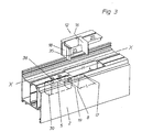
- FIG. 3 shows that a length L of extending in the longitudinal axis X of the frame profile 2 bearing pin 8 is less than the clear height H of the recess 4.
- a packing 12 according to FIG. 3 has a above a free end 17 of the journal 8 and / or the hinge bracket 11 arranged transverse wall 16 and a second foot 19 of the journal 8 enclosing transverse wall 18. Above the transverse wall 16 of the filling body 12 is formed in the form of a cover 20.
- the transverse wall 18 has a recess 35 with which it surrounds the foot 19 of the journal 8.
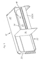
- FIG. 4 is the cover according to FIG. 3 completed in the form of a one-sided open box 22 completed (see also FIG. 5 ), so that one out FIG. 5 apparent additional transverse wall 33 results.
- the transverse walls 16 and 18 are connected by a web 23, which is divided into a fixed portion 24 and a pivotable portion 25.
- the pivotable portion 25 serves in the in FIG. 4 illustrated position of the handling of the filling body 12 in particular during insertion of the filling body in the recess 4; after successful insertion of the pivotable portion 25 can be applied via the indicated at 34 lock against the Zargenan gleichwand 21 in the region of the central chamber 14.
- a designated 27 wall of the filling body 12 is in the inserted position of the filling body 12 to the inner web 26 at.
Landscapes
- Engineering & Computer Science (AREA)
- Mechanical Engineering (AREA)
- Refrigerator Housings (AREA)
- Building Environments (AREA)
- Hinges (AREA)
- Securing Of Glass Panes Or The Like (AREA)
- Extensible Doors And Revolving Doors (AREA)
Description
- Die Erfindung betrifft ein verdecktes Band zur Verbindung eines mehrere Kammern aufweisenden Zargenprofils mit einem Rahmenprofil einer Tür oder eines Fensters, wobei das verdeckte Band in einer Ausnehmung einer falzseitigen Wand eines Zargenprofils verdeckt angeordnet ist, mit einem innerhalb der Ausnehmung im Bereich einer Zargenaußenwand angeordneten Lagerzapfen, mit einem den Lagerzapfen mittels einer Bandhülse drehbar umfassenden an einer falzseitigen Wand des Rahmenprofils angeschlossenen Scharnierbügel, und mit einem die Ausnehmung falzseitig bis auf den Durchtritt für den Scharnierbügel verschließenden Füllkörper.
- Zargenprofile moderner Bauart wiesen aus Gründen der Festigkeit sowie zur Verhinderung von Kältebrücken einen schachtartigen Aufbau auf, das heißt, dass Profil ist durch eine oder mehrere Querstege kammerartig unterteilt. Durch die für das Eintauchen des Scharnierbügels in das Zargenprofil erforderliche Ausnehmung im Zargenprofil erfolgt zwangsläufig eine Unterbrechung der Querstege und damit des schachtartigen Aufbaus im Bereich der Ausnehmung, so dass sich in diesem Bereich eine Kältebrücke bildet, die zu einer unerwünschten Konvektion innerhalb einer oder mehrerer Schächte führen kann. Dieser nachteilige Effekt vergrößert sich mit der Größe der Ausnehmung oder Ausraumung im Zargenprofil.
- Die
DE 198 16 365 A1 beschreibt ein gattungsgemäßes Verschwindscharnier, bei dem der Lagerzapfen im Zargenprofil durch zwei sich parallel zueinander erstreckende Bandlappen gehalten ist. Zum Lösen der Scharnierverbindung im Zargenbereich ist das Entfernen der Bandlappen erforderlich, was zwingend ein erneutes Justieren der Tür beim Wiedereinsetzen erfordert. Ferner ist zum Verschließen der falzseitigen Wandausraumung ein Füllkörper aus Kunststoff vorgesehen. - Die
EP 0 187 337 A2 offenbart eine Türaufhängevorrichtung mit einem Drei-Rollen-Türband, bei dem der Lagerzapfen in Form von Lagereinsätzen dreigeteilt ist und die Lagerhülsen in Achsrichtung der Lagereinsätze zwecks Verriegelung bzw. Entriegelung der Tür spreizbar sind. Die vorgenannte Lösung ist zum einen kostenaufwendig und wegen der erforderlichen Kugellagerung und Spreizvorrichtung störanfällig. - Aus der
DE 298 02 458 U1 ist eine Türaufhängevorrichtung für Holzzargen mit einem Drei-Rollen-Band bekannt geworden, bei dem die Ausnehmung in der Holzzarge durch eine eingesenkte Abdeckplatte mit einer nur der Höhe des Steges des Scharnierbügels entsprechenden Aussparung abgedeckt ist. Das Holzzargenprofil ist hierbei vollwandig ausgebildet. - Die
DE 295 14 335 U1 betrifft eine Stahlzargen-Scharnierkonstruktion mit einem Verschwindscharnier, bei der zur bereichsweisen Abdeckung der Ausnehmung in der Stahlzarge eine Falzabdeckplatte vorgesehen ist. Das Scharnierband besteht ebenfalls aus einem Drei-Rollen-Band, dessen äußere Bandrollen mit einem mit einer Gebäudewand verbundenen Schutzkasten verschraubt sind. - Aufgabe der Erfindung ist es, bei einem Verschwindscharnier eines Profils der eingangs genannten Gattung im Bedarfsfalle das Einsetzen oder Lösen der Tür oder eines Fensterflügels in das Zargenprofil oder vom Zargenprofil zu erleichtern. Dabei soll auf eine Mehrfach-Lagerung des Lagerzapfens am Zargenprofil durch mehrere Bandlappen oder ein Drei-Rollen-Band unter Verwendung spreizbarer Elemente zum Verriegeln und Entriegeln der mittleren Bandrolle verzichtet werden. Ferner ist es Aufgabe der Erfindung, die durch die erfindungsgemäße Lehre bedingte relativ große Ausnehmung oder Ausraumung des Zargenprofils in einer Weise zu verschließen, die die durch die kammerartige oder schachtartige Ausbildung des Zargenprofils entstehende Konvektion verhindert.
- Die Erfindung löst die gestellte Aufgabe durch der Lehre nach Anspruch 1.
- Hiernach sind die Länge des sich parallel zur Ebene des Zargenprofils erstreckenden Lagerzapfens und die Höhe eines Scharnierbügels geringer als die halbe lichte Höhe einer Ausnehmung bemessen, wobei ein Füllkörper wenigstens eine orthogonal zur Längsachse des Zargenprofils verlaufende, die durch die Ausnehmung unterbrochene Kammer verschließende Querwand aufweist.
- Nach Lehre der Erfindung wird somit ein verdecktes Band geschaffen, bei dem die Tür nach Entfernen des Füllkörpers oder Beseitigung von Teilen des Füllkörpers durch einfaches Anheben aus der Zarge herausgehoben werden kann. Die in Folge der Höhe der erforderlichen Ausnehmung bzw. Ausraumung entstehende Kältebrücke und daraus resultierende Konvektion wird zuverlässig durch das zweite Teilmerkmal des Anspruches 1, nämlich durch die Zuordnung einer die unterbrochene Kammer bzw. die unterbrochenen Kammern verschließende Querwand kompensiert.
- Der Füllkörper kann dabei aus einem geeigneten Kunststoff bestehen.
- Weitere Merkmale der Erfindung sind durch die Unteransprüche gekennzeichnet.
- Sofern nur eine Querwand vorgesehen ist, ist diese vorteilhaft oberhalb des freien Endes des Lagerzapfens und/oder des Scharnierbügels angeordnet; es hat sich jedoch als zweckmäßig erwiesen, dass der Füllkörper zwei Querwände aufweist, wobei eine Querwand oberhalb des freien Endes des Lagerzapfens und/oder des Scharnierbügels angeordnet ist und die zweite Querwand den Fuß des Lagerzapfens umschließt. Hierdurch erfolgt eine doppelte Abschottung der Kammern des Zargenprofils, wobei in weiterer Ausgestaltung der Füllkörper oberhalb des freien Endes des Lagerzapfens und/oder des Scharnierbügels als die Ausnehmung falzseitig verschließende Abdeckung ausgebildet sein kann.
- Nach einer bevorzugten Ausführungsform ist der Füllkörper oberhalb des freien Endes des Lagerzapfens und/oder des Scharnierbügels als gegen eine Zargenanschlusswand offener Kasten ausgebildet, das heißt es können drei Querwände realisiert werden, die zuverlässig die durch die Ausnehmung unterbrochenen Kammern sowohl nach unten als auch nach oben abschotten.
- Nach einem weiteren Merkmal der Erfindung ist der Füllkörper derart ausgebildet, dass er einen der Zargenanschlusswand anliegenden Steg aufweist, welcher die oberhalb des freien Endes des Lagerzapfens und/oder des Scharnierbügels angeordnete Querwand und die den Fuß des Lagerzapfens umschließende Querwand verbindet, wobei der vorgenannte Steg in einen die Querwände fest verbindenden Abschnitt und einen gegen die Zargenanschlusswand verschwenkbaren Abschnitt unterteilt sein kann. Diese Unterteilung erfolgt durch eine schwenkbare Verbindung zwischen den beiden vorgenannten Abschnitten, so dass der schwenkbare Abschnitt zum Einsetzen und Ausheben des Füllkörpers in seiner von der Zargenanschlusswand abgeschwenkten Position erfasst werden kann, während er in seiner gegen die Zargenanschlusswand geschwenkten Position zusätzlich der Isolation dient.
- Der Festigkeit einerseits und der zusätzlichen Isolation andererseits dient das weitere Merkmal, das der Füllkörper eine einen Innensteg an einer Mittelkammer des Zargenprofils anliegende Wand aufweist.
- Der Scharnierbügel besitzt eine bei verdeckten Bändern übliche Querschnittsform, wobei ein Schenkel des Scharnierbügels an seinem freien Ende eine Bandhülse trägt. Es hat sich als zweckmäßig erwiesen, an dem die Bandhülse aufweisenden Schenkel des Scharnierbügels einen eine Schwenkbegrenzung bildenden, an der Zargenaußenwand abstützbaren Anschlag anzuordnen.
- Im Ergebnis wird mit der Erfindung ein verdecktes Band vorgeschlagen, bei dem unter Verwendung einer Ausnehmung oder Ausraumung relativ großer Höhe im Zargenprofil die Tür durch Anheben aus der Scharnierverbindung lösbar bzw. in diese Scharnierverbindung einsetzbar ist, wobei gleichzeitig Maßnahmen zur Verhinderung der Konvektion aufgrund der durch die Ausnehmung gebildeten Kältebrücke vorgeschlagen werden.
- Die Erfindung wird nachfolgend anhand von zwei Ausführungsbeispielen näher erläutert.
Es zeigen: - Figur 1:
- Einen Querschnitt durch die Verbindung zwischen dem Zar genprofil und dem Rahmenprofil bei geschlossener Tür.
- Figur 2:
- Die Abbildung gemäß
Figur 1 bei geöffneter Tür. - Figur 3:
- In einer perspektivischen Explosionszeichnung das Zargenprofil mit einem einzusetzenden Füllkörper.
- Figur 4:
- Eine vergrößerte Darstellung des Füllkörpers gemäß
Figur 3 . - Figur 5:
- Eine Ansicht des Füllkörpers gemäß
Figur 4 von der Zargen anschlusswand gesehen. - Ausweislich der
Figuren 1 und 2 verbindet ein verdecktes Band 1 ein Zargenprofil 2 mit einem Rahmenprofil 3, an das eine Tür 6 angeschlossen ist. Zur Erzielung der für den Eingriff eines Scharnierbügels 11 erforderlichen Ausnehmung 4 sind im Bereich der Ausnehmung 4 (siehe auchFigur 3 ) ein Außensteg 37 und eine falzseitige Wand 5 des Zargenprofils 2 bis zum Innensteg 26 entfernt, was in derFigur 1 nicht gesondert dargestellt ist. Unterhalb der Ausnehmung 4 ist an der falzseitigen Wand 5 des Zargenprofils 2 (sieheFigur 3 ) über Bohrungen 36 eine Halterung 30 angeschlossen, welche einen Lagerzapfen 8 trägt. Ein Schenkel 28 des Scharnierbügels 11 umfasst den Lagerzapfen 8 mittels einer Bandhülse 9. Das andere Ende des Scharnierbügels 11 ist über eine Befestigungsplatte 32 an der falzseitigen Wand 10 des Rahmenprofils 3 angeschlossen. Das Zargenprofil 2 ist durch den Innensteg 26 und den Außensteg 37 in eine Außenkammer 13, eine Mittelkammer 14 und eine Innenkammer 15 unterteilt, wobei die Mittelkammer 14 mit einem Isolationsmaterial gefüllt sein kann. Mit 21 ist eine Zargenanschlusswand bezeichnet. -
Figur 3 lässt erkennen, dass eine Länge L des sich in der Längsachse X des Zargenprofils 2 erstreckenden Lagerzapfens 8 geringer ist als die lichte Höhe H der Ausnehmung 4. Ein Füllkörper 12 gemäßFigur 3 weist eine oberhalb eines freien Endes 17 des Lagerzapfens 8 und/oder des Scharnierbügels 11 angeordnete Querwand 16 sowie eine zweite einen Fuß 19 des Lagerzapfens 8 umschließende Querwand 18 auf. Oberhalb der Querwand 16 ist der Füllkörper 12 in Form einer Abdeckung 20 ausgebildet. Die Querwand 18 besitzt eine Ausnehmung 35, mit der sie den Fuß 19 des Lagerzapfens 8 umschließt. - Gemäß dem Ausführungsbeispiel nach
Figur 4 ist die Abdeckung gemäßFigur 3 in Form eines einseitig offenen Kastens 22 vervollständigt ausgebildet (siehe auchFigur 5 ), so dass sich eine ausFigur 5 ersichtliche zusätzliche Querwand 33 ergibt. Die Querwände 16 und 18 sind durch einen Steg 23 verbunden, welcher in einen festen Abschnitt 24 und einen verschwenkbaren Abschnitt 25 unterteilt ist. Der schwenkbare Abschnitt 25 dient in der inFigur 4 dargestellten Position der Handhabung des Füllkörpers 12 insbesondere beim Einsetzen des Füllkörpers in die Ausnehmung 4; nach erfolgtem Einsetzen kann der schwenkbare Abschnitt 25 über die bei 34 angedeutete Verriegelung gegen die Zargenanschlusswand 21 im Bereich der Mittelkammer 14 angelegt werden. Eine mit 27 bezeichnete Wand des Füllkörpers 12 liegt in der eingesetzten Position des Füllkörpers 12 dem Innensteg 26 an. - Aus der
Figur 2 ist ferner ersichtlich, dass zwischen dem Schenkel 28 und einer Zargenaußenwand 7 ein am Schenkel 28 mittels einer Schraubverbindung 38 befestigter, der Schwenkbegrenzung dienender Anschlag 29 vorgesehen ist. -
- 1
- verdecktes Band
- 2
- Zargenprofil
- 3
- Rahmenprofil
- 4
- Ausnehmung
- 5
- falzseitige Wand des Zargenprofils
- 6
- Tür
- 7
- Zargenaußenwand
- 8
- Lagerzapfen
- 9
- Bandhülse
- 10
- falzseitige Wand des Rahmenprofils
- 11
- Scharnierbügel
- 12
- Füllkörper
- 13
- Außenkammer
- 14
- Mittelkammer
- 15
- Innenkammer
- 16
- Querwand
- 17
- freies Ende des Lagerzapfens
- 18
- Querwand
- 19
- Fuß der Lagerzapfens
- 20
- Abdeckung
- 21
- Zargenanschlusswand
- 22
- offener Kasten
- 23
- Steg
- 24
- Abschnitt des Steges
- 25
- Abschnitt des Steges
- 26
- Innensteg
- 27
- Wand
- 28
- Schenkel
- 29
- Anschlag
- 30
- Halterung
- 31
- Halterung
- 32
- Befestigungsplatte
- 33
- Querwand
- 34
- Verriegelung
- 35
- Ausnehmung
- 36
- Bohrungen
- 37
- Außensteg
- 38
- Schraubverbindung
- L
- Länge des Lagerzapfens
- H
- lichte Höhe der Ausnehmung
- X
- Längsachse des Zargenprofils
Claims (9)
- Verdecktes Band (1) zur Verbindung eines mehrere Kammern (13, 14, 15) aufweisenden Zargenprofils (2) mit einem Rahmenprofil (3) an einer Tür (6) oder eines Fensters, wobei das verdeckte Band in einer Ausnehmung (4) einer falzseitigen Wand (5) eines Zargenprofils (2) verdeckt angeordnet ist, mit einem innerhalb der Ausnehmung (4) im Bereich einer Zargenaußenwand (7) angeordneten Lagerzapfen (8), mit einem den Lagerzapfen (8) mittels einer Bandhülse (9) drehbar umfassenden, an einer falzseitigen Wand (10) des Rahmenprofils (3) angeschlossenen Scharnierbügel (11), und mit einem die Ausnehmung (4) falzseitig bis auf den Durchtritt für den Scharnierbügel (11) verschließenden Füllkörper (12), gekennzeichnet durch folgende Merkmale:a) eine Länge (L) des sich parallel zur Ebene des Zargenprofils (2) erstreckenden Lagerzapfens (8) und eine Höhe des Scharnierbügels (11) sind geringer als eine halbe lichte Höhe (H) der Ausnehmung (4);b) der Füllkörper (12) weist wenigstens eine orthogonal zur Längsachse (X) des Zargenprofils (2) verlaufende, eine durch die Ausnehmung (4) unterbrochene (n) Kammer (n) (13, 14, 15) verschließende Querwand (16) auf.
- Verdecktes Band nach Anspruch 1, dadurch gekennzeichnet,
dass die Querwand (16) oberhalb eines freien Endes (17) des Lagerzapfens (8) und/oder des Scharnierbügels (11) angeordnet ist. - Verdecktes Band nach Anspruch 1 und 2, dadurch gekennzeichnet, dass der Füllkörper (12) zwei Querwände (16, 18) aufweist, wobei eine Querwand (16) oberhalb des freien Endes (17) des Lagerzapfens (8) und/oder des Scharnierbügels (11) angeordnet ist und die zweite Querwand (18) einen Fuß (19) des Lagerzapfens (8) umschließt.
- Verdecktes Band nach einem der Ansprüche 1 bis 3, dadurch gekennzeichnet, dass der Füllkörper (12) oberhalb des freien Endes (17) des Lagerzapfens (8) und/oder des Scharnierbügels (11) als die Ausnehmung (4) falzseitig verschließende Abdeckung (20) ausgebildet ist.
- Verdecktes Band nach einem der Ansprüche 1 bis 4, dadurch gekennzeichnet, dass der Füllkörper (12) oberhalb des freien Endes (17) des Lagerzapfens (8) und/oder des Scharnierbügels (11) als gegen eine Zargenanschlusswand (21) offener Kasten (22) ausgebildet ist.
- Verdecktes Band nach einem der Ansprüche 1 bis 5, dadurch gekennzeichnet, dass die oberhalb des freien Endes (17) des Lagerzapfens (8) und/oder des Scharnierbügels (11) angeordnete Querwand (16) und die den Fuß (19) des Lagerzapfens (8) umschließende Querwand (18) durch einen der Zargenanschlusswand (21) anliegenden Steg (23) verbunden sind.
- Verdecktes Band nach Anspruch 6, dadurch gekennzeichnet, dass der Steg (23) in einen die Querwände fest verbindenden Abschnitt (24) und einen gegen die Zargenanschlusswand (21) verschwenkbaren Abschnitt (25) unterteilt ist.
- Verdecktes Band nach einem der Ansprüche 1 bis 7, dadurch gekennzeichnet, dass der Füllkörper (12) eine einen Innensteg (26) einer Mittelkammer (14) des Zargenprofils (2) anliegende Wand (27) aufweist.
- Verdecktes Band nach einem der Ansprüche 1 bis 8, dadurch gekennzeichnet, dass an einem die Bandhülse (9) aufweisenden Schenkel (28) des Scharnierbügels (11) ein eine Schwenkbegrenzung bildender, an der Zargenaußenwand (7) abstützbarer Anschlag (29) angeordnet ist.
Applications Claiming Priority (2)
| Application Number | Priority Date | Filing Date | Title |
|---|---|---|---|
| DE10009630A DE10009630C2 (de) | 2000-03-01 | 2000-03-01 | Verdecktes Band |
| DE10009630 | 2000-03-01 |
Publications (3)
| Publication Number | Publication Date |
|---|---|
| EP1130207A2 EP1130207A2 (de) | 2001-09-05 |
| EP1130207A3 EP1130207A3 (de) | 2005-03-16 |
| EP1130207B1 true EP1130207B1 (de) | 2009-04-08 |
Family
ID=7632892
Family Applications (1)
| Application Number | Title | Priority Date | Filing Date |
|---|---|---|---|
| EP01104275A Expired - Lifetime EP1130207B1 (de) | 2000-03-01 | 2001-02-22 | Verdecktes Band |
Country Status (5)
| Country | Link |
|---|---|
| EP (1) | EP1130207B1 (de) |
| AT (1) | ATE428039T1 (de) |
| DE (2) | DE10009630C2 (de) |
| DK (1) | DK1130207T3 (de) |
| ES (1) | ES2325201T3 (de) |
Families Citing this family (2)
| Publication number | Priority date | Publication date | Assignee | Title |
|---|---|---|---|---|
| DE20100621U1 (de) * | 2001-01-12 | 2002-05-23 | Dr. Hahn GmbH & Co. KG, 41189 Mönchengladbach | Dichtmittel für an Hohlprofilen angebrachte Bandanordnung für Türen, Fenster u.dgl. |
| EP4124712B1 (de) * | 2021-07-27 | 2026-03-25 | Giesse S.P.A. | Scharnier für eine tür oder ein fenster und verfahren zur montage des scharniers an einer tür oder einem fenster |
Family Cites Families (5)
| Publication number | Priority date | Publication date | Assignee | Title |
|---|---|---|---|---|
| EP0187337B1 (de) * | 1984-12-21 | 1990-04-18 | Friedrich Puchtler | Türaufhängevorrichtung |
| CZ38693A3 (en) * | 1992-03-13 | 1993-11-17 | Betonbau Gmbh | Device for closing holes in walls, particularly inlets for switching stations |
| DE29514335U1 (de) * | 1995-09-07 | 1997-01-09 | Breuer & Schmitz, 42719 Solingen | Stahlzargen-Scharnierkonstruktion |
| DE29802458U1 (de) * | 1998-02-13 | 1998-04-23 | Hans Weber Metallwarenfabrik GmbH, 90443 Nürnberg | Türaufhängevorrichtung für stumpf angeschlagene Türen mit Holzzargen |
| DE19816365A1 (de) * | 1998-04-03 | 1999-10-14 | Dieter Fischer | Verschwindscharnier |
-
2000
- 2000-03-01 DE DE10009630A patent/DE10009630C2/de not_active Expired - Fee Related
-
2001
- 2001-02-22 DK DK01104275T patent/DK1130207T3/da active
- 2001-02-22 EP EP01104275A patent/EP1130207B1/de not_active Expired - Lifetime
- 2001-02-22 DE DE50114812T patent/DE50114812D1/de not_active Expired - Lifetime
- 2001-02-22 ES ES01104275T patent/ES2325201T3/es not_active Expired - Lifetime
- 2001-02-22 AT AT01104275T patent/ATE428039T1/de not_active IP Right Cessation
Also Published As
| Publication number | Publication date |
|---|---|
| ES2325201T3 (es) | 2009-08-28 |
| DK1130207T3 (da) | 2009-08-10 |
| EP1130207A2 (de) | 2001-09-05 |
| DE50114812D1 (de) | 2009-05-20 |
| DE10009630C2 (de) | 2002-12-05 |
| EP1130207A3 (de) | 2005-03-16 |
| DE10009630A1 (de) | 2001-09-13 |
| ATE428039T1 (de) | 2009-04-15 |
Similar Documents
| Publication | Publication Date | Title |
|---|---|---|
| EP0460620B1 (de) | Türband | |
| EP1238179B1 (de) | Baugruppe mit einem band für türen, fenster oder dergleichen | |
| WO1993010325A1 (de) | Rolladen | |
| DE10066405B4 (de) | Insektenschutztür | |
| DE29602084U1 (de) | Bandanordnung für Türen, Fenster u.dgl. | |
| DE29703324U1 (de) | Band für Türen, Fenster u.dgl. | |
| DE19816365A1 (de) | Verschwindscharnier | |
| DE9407569U1 (de) | Einbruchsicherung | |
| DE10009630C2 (de) | Verdecktes Band | |
| DE19959736C2 (de) | Rolladen-Aufsatzkasten | |
| DE19834700B4 (de) | Vorrichtung zum Verschließen einer Wandöffnung | |
| EP0074502A1 (de) | Sektional-tor | |
| EP0187337B1 (de) | Türaufhängevorrichtung | |
| DE60010806T2 (de) | Verdeckter Öffnungsbeschlag für Drehflügeltür oder -Fenster | |
| DE19607557A1 (de) | Nachrüstzarge für Türen | |
| DE8423562U1 (de) | Scharnier | |
| DE3511776C2 (de) | ||
| DE3625105C1 (en) | Door hinge for a sheet-metal or plastic cupboard | |
| EP0789123B1 (de) | Bandanordnung für Türen, Fenster und dergleichen | |
| DE3613122C2 (de) | ||
| DE2442473C2 (de) | Zargenunterband für Holz- oder Kunststoffzargen für rechts- oder linksanschlagbare Normtüren | |
| DE29802458U1 (de) | Türaufhängevorrichtung für stumpf angeschlagene Türen mit Holzzargen | |
| DE7244357U (de) | Scharnierteil fuer einen fluegel insbesondere einen schwenk-kippfluegel eines fensters einer tuer od.dgl. | |
| DE29805362U1 (de) | Kantriegelverschluß | |
| DE102006041701A1 (de) | Drehstangenverschluß für eine Türverriegelung |
Legal Events
| Date | Code | Title | Description |
|---|---|---|---|
| PUAI | Public reference made under article 153(3) epc to a published international application that has entered the european phase |
Free format text: ORIGINAL CODE: 0009012 |
|
| AK | Designated contracting states |
Kind code of ref document: A2 Designated state(s): AT BE CH CY DE DK ES FI FR GB GR IE IT LI LU MC NL PT SE TR |
|
| AX | Request for extension of the european patent |
Free format text: AL;LT;LV;MK;RO;SI |
|
| PUAL | Search report despatched |
Free format text: ORIGINAL CODE: 0009013 |
|
| AK | Designated contracting states |
Kind code of ref document: A3 Designated state(s): AT BE CH CY DE DK ES FI FR GB GR IE IT LI LU MC NL PT SE TR |
|
| AX | Request for extension of the european patent |
Extension state: AL LT LV MK RO SI |
|
| RIC1 | Information provided on ipc code assigned before grant |
Ipc: 7E 05D 5/06 B Ipc: 7E 05D 7/10 B Ipc: 7E 05D 5/02 A |
|
| 17P | Request for examination filed |
Effective date: 20050916 |
|
| AKX | Designation fees paid |
Designated state(s): AT BE CH CY DE DK ES FI FR GB GR IE IT LI LU MC NL PT SE TR |
|
| GRAP | Despatch of communication of intention to grant a patent |
Free format text: ORIGINAL CODE: EPIDOSNIGR1 |
|
| GRAS | Grant fee paid |
Free format text: ORIGINAL CODE: EPIDOSNIGR3 |
|
| GRAA | (expected) grant |
Free format text: ORIGINAL CODE: 0009210 |
|
| AK | Designated contracting states |
Kind code of ref document: B1 Designated state(s): AT BE CH CY DE DK ES FI FR GB GR IE IT LI LU MC NL PT SE TR |
|
| REG | Reference to a national code |
Ref country code: GB Ref legal event code: FG4D Free format text: NOT ENGLISH |
|
| REG | Reference to a national code |
Ref country code: CH Ref legal event code: EP |
|
| REG | Reference to a national code |
Ref country code: IE Ref legal event code: FG4D |
|
| REF | Corresponds to: |
Ref document number: 50114812 Country of ref document: DE Date of ref document: 20090520 Kind code of ref document: P |
|
| REG | Reference to a national code |
Ref country code: CH Ref legal event code: NV Representative=s name: BOVARD AG PATENTANWAELTE |
|
| REG | Reference to a national code |
Ref country code: SE Ref legal event code: TRGR |
|
| REG | Reference to a national code |
Ref country code: DK Ref legal event code: T3 |
|
| REG | Reference to a national code |
Ref country code: ES Ref legal event code: FG2A Ref document number: 2325201 Country of ref document: ES Kind code of ref document: T3 |
|
| NLV1 | Nl: lapsed or annulled due to failure to fulfill the requirements of art. 29p and 29m of the patents act | ||
| PG25 | Lapsed in a contracting state [announced via postgrant information from national office to epo] |
Ref country code: PT Free format text: LAPSE BECAUSE OF FAILURE TO SUBMIT A TRANSLATION OF THE DESCRIPTION OR TO PAY THE FEE WITHIN THE PRESCRIBED TIME-LIMIT Effective date: 20090908 |
|
| PG25 | Lapsed in a contracting state [announced via postgrant information from national office to epo] |
Ref country code: NL Free format text: LAPSE BECAUSE OF FAILURE TO SUBMIT A TRANSLATION OF THE DESCRIPTION OR TO PAY THE FEE WITHIN THE PRESCRIBED TIME-LIMIT Effective date: 20090408 |
|
| PLBE | No opposition filed within time limit |
Free format text: ORIGINAL CODE: 0009261 |
|
| STAA | Information on the status of an ep patent application or granted ep patent |
Free format text: STATUS: NO OPPOSITION FILED WITHIN TIME LIMIT |
|
| 26N | No opposition filed |
Effective date: 20100111 |
|
| BERE | Be: lapsed |
Owner name: DORMA G.M.B.H. + CO. KG Effective date: 20100228 |
|
| REG | Reference to a national code |
Ref country code: CH Ref legal event code: PL |
|
| REG | Reference to a national code |
Ref country code: DK Ref legal event code: EBP |
|
| EUG | Se: european patent has lapsed | ||
| GBPC | Gb: european patent ceased through non-payment of renewal fee |
Effective date: 20100222 |
|
| PG25 | Lapsed in a contracting state [announced via postgrant information from national office to epo] |
Ref country code: GR Free format text: LAPSE BECAUSE OF FAILURE TO SUBMIT A TRANSLATION OF THE DESCRIPTION OR TO PAY THE FEE WITHIN THE PRESCRIBED TIME-LIMIT Effective date: 20090709 Ref country code: CH Free format text: LAPSE BECAUSE OF NON-PAYMENT OF DUE FEES Effective date: 20100228 Ref country code: LI Free format text: LAPSE BECAUSE OF NON-PAYMENT OF DUE FEES Effective date: 20100228 Ref country code: MC Free format text: LAPSE BECAUSE OF NON-PAYMENT OF DUE FEES Effective date: 20100301 |
|
| REG | Reference to a national code |
Ref country code: FR Ref legal event code: ST Effective date: 20101029 |
|
| REG | Reference to a national code |
Ref country code: IE Ref legal event code: MM4A |
|
| PG25 | Lapsed in a contracting state [announced via postgrant information from national office to epo] |
Ref country code: FI Free format text: LAPSE BECAUSE OF NON-PAYMENT OF DUE FEES Effective date: 20100222 |
|
| PG25 | Lapsed in a contracting state [announced via postgrant information from national office to epo] |
Ref country code: IE Free format text: LAPSE BECAUSE OF NON-PAYMENT OF DUE FEES Effective date: 20100222 Ref country code: DK Free format text: LAPSE BECAUSE OF NON-PAYMENT OF DUE FEES Effective date: 20100228 Ref country code: FR Free format text: LAPSE BECAUSE OF NON-PAYMENT OF DUE FEES Effective date: 20100301 |
|
| PG25 | Lapsed in a contracting state [announced via postgrant information from national office to epo] |
Ref country code: BE Free format text: LAPSE BECAUSE OF NON-PAYMENT OF DUE FEES Effective date: 20100228 |
|
| REG | Reference to a national code |
Ref country code: ES Ref legal event code: FD2A Effective date: 20110310 |
|
| PG25 | Lapsed in a contracting state [announced via postgrant information from national office to epo] |
Ref country code: IT Free format text: LAPSE BECAUSE OF NON-PAYMENT OF DUE FEES Effective date: 20100222 Ref country code: GB Free format text: LAPSE BECAUSE OF NON-PAYMENT OF DUE FEES Effective date: 20100222 |
|
| PG25 | Lapsed in a contracting state [announced via postgrant information from national office to epo] |
Ref country code: AT Free format text: LAPSE BECAUSE OF NON-PAYMENT OF DUE FEES Effective date: 20100222 |
|
| PGFP | Annual fee paid to national office [announced via postgrant information from national office to epo] |
Ref country code: DE Payment date: 20110218 Year of fee payment: 11 |
|
| PG25 | Lapsed in a contracting state [announced via postgrant information from national office to epo] |
Ref country code: ES Free format text: LAPSE BECAUSE OF NON-PAYMENT OF DUE FEES Effective date: 20110309 |
|
| PG25 | Lapsed in a contracting state [announced via postgrant information from national office to epo] |
Ref country code: ES Free format text: LAPSE BECAUSE OF NON-PAYMENT OF DUE FEES Effective date: 20100223 |
|
| PG25 | Lapsed in a contracting state [announced via postgrant information from national office to epo] |
Ref country code: CY Free format text: LAPSE BECAUSE OF FAILURE TO SUBMIT A TRANSLATION OF THE DESCRIPTION OR TO PAY THE FEE WITHIN THE PRESCRIBED TIME-LIMIT Effective date: 20090408 |
|
| PG25 | Lapsed in a contracting state [announced via postgrant information from national office to epo] |
Ref country code: LU Free format text: LAPSE BECAUSE OF NON-PAYMENT OF DUE FEES Effective date: 20100222 Ref country code: SE Free format text: LAPSE BECAUSE OF NON-PAYMENT OF DUE FEES Effective date: 20100223 |
|
| PG25 | Lapsed in a contracting state [announced via postgrant information from national office to epo] |
Ref country code: TR Free format text: LAPSE BECAUSE OF FAILURE TO SUBMIT A TRANSLATION OF THE DESCRIPTION OR TO PAY THE FEE WITHIN THE PRESCRIBED TIME-LIMIT Effective date: 20090408 |
|
| REG | Reference to a national code |
Ref country code: DE Ref legal event code: R119 Ref document number: 50114812 Country of ref document: DE Effective date: 20120901 |
|
| PG25 | Lapsed in a contracting state [announced via postgrant information from national office to epo] |
Ref country code: DE Free format text: LAPSE BECAUSE OF NON-PAYMENT OF DUE FEES Effective date: 20120901 |