EP1130246A2 - Dosierventilbaugruppe mit Druckausgleichvorrichtung für ein modulares Abgasrückführungsventil - Google Patents
Dosierventilbaugruppe mit Druckausgleichvorrichtung für ein modulares Abgasrückführungsventil Download PDFInfo
- Publication number
- EP1130246A2 EP1130246A2 EP01200650A EP01200650A EP1130246A2 EP 1130246 A2 EP1130246 A2 EP 1130246A2 EP 01200650 A EP01200650 A EP 01200650A EP 01200650 A EP01200650 A EP 01200650A EP 1130246 A2 EP1130246 A2 EP 1130246A2
- Authority
- EP
- European Patent Office
- Prior art keywords
- valve
- actuator
- pintle
- disposed
- pintle shaft
- Prior art date
- Legal status (The legal status is an assumption and is not a legal conclusion. Google has not performed a legal analysis and makes no representation as to the accuracy of the status listed.)
- Withdrawn
Links
- 238000002485 combustion reaction Methods 0.000 claims abstract description 8
- 230000006835 compression Effects 0.000 claims description 5
- 238000007906 compression Methods 0.000 claims description 5
- 230000013011 mating Effects 0.000 claims description 5
- 230000007797 corrosion Effects 0.000 abstract description 4
- 238000005260 corrosion Methods 0.000 abstract description 4
- 238000009434 installation Methods 0.000 abstract description 2
- 239000007789 gas Substances 0.000 description 24
- 238000007789 sealing Methods 0.000 description 4
- 230000008901 benefit Effects 0.000 description 3
- 239000000446 fuel Substances 0.000 description 3
- 239000002184 metal Substances 0.000 description 3
- 229910052751 metal Inorganic materials 0.000 description 3
- IJGRMHOSHXDMSA-UHFFFAOYSA-N Atomic nitrogen Chemical compound N#N IJGRMHOSHXDMSA-UHFFFAOYSA-N 0.000 description 2
- XEEYBQQBJWHFJM-UHFFFAOYSA-N Iron Chemical compound [Fe] XEEYBQQBJWHFJM-UHFFFAOYSA-N 0.000 description 2
- 238000004891 communication Methods 0.000 description 2
- 239000000463 material Substances 0.000 description 2
- 230000009286 beneficial effect Effects 0.000 description 1
- 230000015572 biosynthetic process Effects 0.000 description 1
- 238000010276 construction Methods 0.000 description 1
- 239000000356 contaminant Substances 0.000 description 1
- 239000000428 dust Substances 0.000 description 1
- 229920001971 elastomer Polymers 0.000 description 1
- 239000000806 elastomer Substances 0.000 description 1
- 239000012530 fluid Substances 0.000 description 1
- 229910052742 iron Inorganic materials 0.000 description 1
- 230000007257 malfunction Effects 0.000 description 1
- 150000002739 metals Chemical class 0.000 description 1
- 239000000203 mixture Substances 0.000 description 1
- 238000012986 modification Methods 0.000 description 1
- 230000004048 modification Effects 0.000 description 1
- MWUXSHHQAYIFBG-UHFFFAOYSA-N nitrogen oxide Inorganic materials O=[N] MWUXSHHQAYIFBG-UHFFFAOYSA-N 0.000 description 1
- 229920000642 polymer Polymers 0.000 description 1
- 239000000843 powder Substances 0.000 description 1
- XTQHKBHJIVJGKJ-UHFFFAOYSA-N sulfur monoxide Chemical class S=O XTQHKBHJIVJGKJ-UHFFFAOYSA-N 0.000 description 1
- 229910052815 sulfur oxide Inorganic materials 0.000 description 1
- 238000013022 venting Methods 0.000 description 1
Images
Classifications
-
- F—MECHANICAL ENGINEERING; LIGHTING; HEATING; WEAPONS; BLASTING
- F02—COMBUSTION ENGINES; HOT-GAS OR COMBUSTION-PRODUCT ENGINE PLANTS
- F02M—SUPPLYING COMBUSTION ENGINES IN GENERAL WITH COMBUSTIBLE MIXTURES OR CONSTITUENTS THEREOF
- F02M26/00—Engine-pertinent apparatus for adding exhaust gases to combustion-air, main fuel or fuel-air mixture, e.g. by exhaust gas recirculation [EGR] systems
- F02M26/65—Constructional details of EGR valves
- F02M26/66—Lift valves, e.g. poppet valves
- F02M26/67—Pintles; Spindles; Springs; Bearings; Sealings; Connections to actuators
-
- F—MECHANICAL ENGINEERING; LIGHTING; HEATING; WEAPONS; BLASTING
- F02—COMBUSTION ENGINES; HOT-GAS OR COMBUSTION-PRODUCT ENGINE PLANTS
- F02M—SUPPLYING COMBUSTION ENGINES IN GENERAL WITH COMBUSTIBLE MIXTURES OR CONSTITUENTS THEREOF
- F02M26/00—Engine-pertinent apparatus for adding exhaust gases to combustion-air, main fuel or fuel-air mixture, e.g. by exhaust gas recirculation [EGR] systems
- F02M26/50—Arrangements or methods for preventing or reducing deposits, corrosion or wear caused by impurities
-
- F—MECHANICAL ENGINEERING; LIGHTING; HEATING; WEAPONS; BLASTING
- F02—COMBUSTION ENGINES; HOT-GAS OR COMBUSTION-PRODUCT ENGINE PLANTS
- F02M—SUPPLYING COMBUSTION ENGINES IN GENERAL WITH COMBUSTIBLE MIXTURES OR CONSTITUENTS THEREOF
- F02M26/00—Engine-pertinent apparatus for adding exhaust gases to combustion-air, main fuel or fuel-air mixture, e.g. by exhaust gas recirculation [EGR] systems
- F02M26/52—Systems for actuating EGR valves
- F02M26/53—Systems for actuating EGR valves using electric actuators, e.g. solenoids
Definitions
- the present invention relates to pintle-type valves; more particularly to solenoid-actuated pintle valves for permitting the controlled admission of exhaust gases into the fuel intake manifold of an internal combustion engine; and most particularly to a system including an interrupted pintle and gas arrestor for preventing entrance of corrosive gases and moisture into the valve actuator.
- an EGR valve has a valve body enclosing a chamber disposed between a first port in the exhaust manifold and a second port in the intake manifold; a valve seat dividing the chamber between the two ports; a pintle shaft having a valve head fitted to the valve seat and extending from the valve head through a bearing mounted in a third port in a sidewall of the valve body; a spring-retained bearing splash shield; and a solenoid actuator mounted on the exterior of the valve body and having an armature into which the outer end of the valve pintle extends.
- a problem inherent to EGR valve applications is that the managed fluid (exhaust gas) is moisture-laden, corrosive, and dirty. If this gas enters the actuator, for example, by leaking along the pintle shaft, then internal corrosion, malfunction, and ultimate failure of the actuator can result. Such failure can lead to emission non-compliance and can incur significant cost to a vehicle manufacturer if a recall is required.
- a gas arrestor between an EGR valve and actuator that prevents gas and moisture intrusion into the actuator without impairing efficiency, size, and performance of the valve and actuator.
- an arrestor is simple and inexpensive to fabricate and install.
- the present invention is directed to a leakage arresting system comprising a novel gas arrestor for installation on an interrupted pintle shaft in a pintle-type valve, such as an exhaust gas recirculation valve for an internal combustion engine, for preventing leakage of gas and moisture along the pintle shaft into the actuator to prevent corrosion and failure of the actuator.
- the system comprises two elements: a pintle shaft which is interrupted outside the actuator, and a positive vapor block in the form of a cup-shaped arrestor disposed across the pintle interruption.
- the invention is applicable to both unbalanced and force-balanced valves.
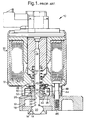
- a prior art EGR valve 10 includes a valve body 12 having a valve seat 14 separating a first chamber 16 from a second chamber 18, which chambers may communicate with the exhaust and intake systems, respectively, of an internal combustion engine (not shown) or the reverse.
- Valve head 20 is disposed adjacent to seat 14 for selectively mating therewith to open or to close communication between chambers 16 and 18.
- Valve pintle shaft 22 extends from head 20 through an axial bore 24 in bearing 26 and is captured within armature 28 of solenoid actuator 30.
- Bearing 26 is disposed in a port 27 in a wall of valve body 12 and guides shaft 22 in reciprocating motion to open and close the valve when actuator 30 is energized and de-energized, respectively.
- Bearing 26 is provided with a circumferential flange 32 having an axial face 34 for sealing against axial outer surface 36 of valve body 12 to prevent leakage of gases therebetween.
- a cup-shaped bearing splash shield 38 has an inward-extending flange 40 with a central aperture for passage of shaft 22, preferably without contact therebetween, and a cylindrical skirt 44 extending axially to shield a substantial portion of bearing 26 from external contaminants. Shield 38 is open in a downwards direction to permit venting of any gases which may leak along bore 24 during operation of the valve.
- Actuator 30 is connected to valve body 12 via a plurality of bolts 46 extending through a plurality of standoffs 48.
- a coil spring 50 surrounding pintle shaft 22 is disposed within shield 38, being compressed between actuator 30 and a second surface 52 on flange 32 for urging flange 32 to seal against surface 36 under all operating conditions.
- Spring 50 also serves to urge shield 38 against surface 49 of primary polepiece 51 of actuator 30 to inhibit dust intrusion into the actuator.
- a second spring 54 disposed in compression within actuator 30 between armature 28 and polepiece 51 keeps valve 10 in the normally-closed position shown in FIG. 1 when the solenoid is de-energized, pintle shaft 22 thus being under tension.
- pintle shaft 22 is subjected to compressive force, an important consideration in providing an interrupted pintle shaft and gas arrestor in accordance with the invention.
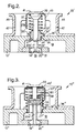
- valve 10' in accordance with the invention is shown, for clarity without an actuator.
- valve 10' has a valve body 12' having a valve seat 14' separating a first chamber 16 (outside of the valve body in this embodiment but analogous to chamber 16 in FIG. 1) from a second chamber 18.
- Valve head 20' having a mating element 21 attached thereto as by any conventional means is disposed adjacent to seat 14' for selectively mating therewith to open or to close communication between chambers 16 and 18.
- Pintle shaft 22' extends from head 20' through an axial bore 24' in bearing 26'.
- Bearing 26' is disposed in a port 27' in a wall of valve body 12' and guides pintle shaft 22' in reciprocating motion to open and close the valve when the actuator (not shown) is energized and de-energized, respectively.
- Bearing 26' is provided with a circumferential flange 32' having a first axial face 34' for sealing against axial outer surface 36' of valve body 12' to prevent leakage of gases therebetween.
- the diameter of port 27' is slightly greater than the diameter of the corresponding portion of bearing 26', providing a gap 29 therebetween, such that the bearing may be radially compliant to accommodate axial misalignments of other valve components.
- pintle shaft 22' may be provided in upper and lower sections 22'a,22'b which are threaded appropriately to screw together to form pintle shaft 22'.
- pintle shaft 22' may be provided as a one-piece element, and the metering head may be attached conventionally.
- Pintle shaft 22' terminates in a flared portion 39 having a flat outer surface 41.
- a gas arrestor 43 cup-shaped and inverted downwards, has a central aperture for receiving portion 39.
- Arrestor 43 is readily and inexpensively formed as by stamping from sheet metal.
- a coil spring 50' is disposed in compression around pintle shaft 22a' between bearing flange 32' and the underside of arrestor 43, urging the arrestor into sealing contact with the underside of flared portion 39.
- Actuator standoffs 45 are attached to valve body 12' and are provided with one or more vents 47.
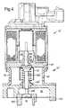
- valve 10' just described and shown in FIG. 2 is here shown fully attached to an actuator 30' modified as necessary to interface with the shortened pintle shaft 22'.
- Valve 10' is shown mounted for use as an exhaust gas recirculation (EGR) valve on an internal combustion engine 104, exhaust manifold 100 and intake manifold 102 being attached to valve 10' adjacent chambers 16 and 18, respectively.
- EGR exhaust gas recirculation
- second spring 54 is eliminated.
- the outer portion of pintle shaft 22 extending into and captured by armature 28 is replaced by a stub shaft, or pintle lifter, 22'c which makes contact with but is not connected to surface 41.
- pintle shaft elements 22'a, 22'b, and 22'c may be thought of as an "interrupted" pintle shaft having a positive gas-arresting break between elements 22'b and 22'c.
- Pintle lifter 22'c is radially supported and guided by a new flanged bearing 62, similar to bearing 26', disposed preferably as a press fit in a new axial bore 64 in modified polepiece 51'.
- the length of lifter 22'c in the bearing is at least 1.5 times the diameter of lifter 22'c to inhibit potential ingress of gas and moisture into actuator 30' through bearing 62.
- valve head 20' is urged towards the closed valve position by spring 50', armature 28 and pintle lifter 22'c act on pintle shaft 22' only under compression. Because surface 41 presents a relatively broad contact surface for pintle lifter 22'c, the axial alignment of actuator 30' with valve 10' is significantly relaxed over the tight tolerance required in prior art valve 10.
- a second embodiment 10" of a valve with a gas arrestor in accordance with the invention is configured as a force-balanced valve.
- Valve 10' is not force-balanced in that pressure or vacuum in chamber 18 exerts an opening or closing force on the back side of valve head 20' which must be overcome by spring 50' for the valve to remain closed or by actuator 30' for the valve to open.
- the operating range of valve 10' is limited to pressures below the spring force of the closing spring and the solenoid force of the actuator.
- valve 10 In valve 10", however, a piston 53 having a cross-sectional area substantially equivalent to the area of valve head 20' is disposed on pintle shaft 22a" in opposition to head 20' such that the opening or closing force exerted on head 20' is balanced by an equal closing or opening force exerted on piston 53.
- valve 10" may be used over a broader range of internal pressures than valve 10'.
- piston 53 effectively takes the place of bearing 26' in guiding the pintle shaft in the valve.
- a piston cylinder 55 is disposed in a bore 27" in valve body 12" to be radially-compliant as described above for bearing 26' in valve body 12'.
- Cylinder 55 is provided with a flange 32" for supporting and sealing against surface 36".
- Piston 53 is slidingly disposed within cylinder 55, the diametral tolerance between piston 53 and cylinder 55 being as small as possible without causing significant drag therebetween.
- Pintle shaft 22a" extends beyond piston 53 and is terminated in a broad, flat cap 56 having an upper surface 41.
- a second embodiment 43' of a gas arrestor is disposed on shaft 22a" and a coil spring 50" in compression is captured between arrestor 43' and flange 32", again for urging arrestor 43' sealingly against cap 56 and for urging head 20" into closed relationship with seat 14".
- cylinder 55 preferably is provided with an inwardly curved flange 58 for receiving a shaft seal 60 which may be formed from an appropriate material, for example, an elastomer, metal, or polymer, and disposed with minimal radial pressure on shaft 22a".
Landscapes
- Engineering & Computer Science (AREA)
- Chemical & Material Sciences (AREA)
- Combustion & Propulsion (AREA)
- Mechanical Engineering (AREA)
- General Engineering & Computer Science (AREA)
- Exhaust-Gas Circulating Devices (AREA)
Applications Claiming Priority (4)
| Application Number | Priority Date | Filing Date | Title |
|---|---|---|---|
| US18453300P | 2000-02-24 | 2000-02-24 | |
| US18453000P | 2000-02-24 | 2000-02-24 | |
| US184530P | 2000-02-24 | ||
| US184533P | 2000-02-24 |
Publications (2)
| Publication Number | Publication Date |
|---|---|
| EP1130246A2 true EP1130246A2 (de) | 2001-09-05 |
| EP1130246A3 EP1130246A3 (de) | 2002-08-28 |
Family
ID=26880219
Family Applications (1)
| Application Number | Title | Priority Date | Filing Date |
|---|---|---|---|
| EP01200650A Withdrawn EP1130246A3 (de) | 2000-02-24 | 2001-02-22 | Dosierventilbaugruppe mit Druckausgleichvorrichtung für ein modulares Abgasrückführungsventil |
Country Status (1)
| Country | Link |
|---|---|
| EP (1) | EP1130246A3 (de) |
Cited By (2)
| Publication number | Priority date | Publication date | Assignee | Title |
|---|---|---|---|---|
| EP1398494A1 (de) * | 2002-09-06 | 2004-03-17 | Delphi Technologies, Inc. | Abgasrückführventil mit niedrigem Luftwiderstand |
| DE112007003021B4 (de) * | 2006-12-28 | 2016-12-01 | Mitsubishi Electric Corp. | Abgasrücklaufventil |
Citations (2)
| Publication number | Priority date | Publication date | Assignee | Title |
|---|---|---|---|---|
| EP0461688A1 (de) * | 1990-06-13 | 1991-12-18 | General Motors Corporation | Aufbau eines Abgasrückführungsventils |
| EP0962646A1 (de) * | 1997-10-22 | 1999-12-08 | Mitsubishi Denki Kabushiki Kaisha | Kontrollventil für abgasrückführung |
Family Cites Families (6)
| Publication number | Priority date | Publication date | Assignee | Title |
|---|---|---|---|---|
| DE4039351A1 (de) * | 1990-12-10 | 1992-06-11 | Pierburg Gmbh | Elektromagnetisches steuerventil fuer abgasrueckfuehrung |
| JP3479353B2 (ja) * | 1994-10-17 | 2003-12-15 | 株式会社ケーヒン | 排気ガス再循環バルブ |
| US5669364A (en) * | 1996-11-21 | 1997-09-23 | Siemens Electric Limited | Exhaust gas recirculation valve installation for a molded intake manifold |
| US5960776A (en) * | 1996-11-21 | 1999-10-05 | Siemens Canada Limited | Exhaust gas recirculation valve having a centered solenoid assembly and floating valve mechanism |
| DE19752495A1 (de) * | 1997-11-27 | 1999-06-02 | Pierburg Ag | Abgasrückführventil für Brennkraftmaschinen |
| US6182684B1 (en) * | 1998-03-19 | 2001-02-06 | Robertshaw Controls Company | Bellows balanced valve |
-
2001
- 2001-02-22 EP EP01200650A patent/EP1130246A3/de not_active Withdrawn
Patent Citations (2)
| Publication number | Priority date | Publication date | Assignee | Title |
|---|---|---|---|---|
| EP0461688A1 (de) * | 1990-06-13 | 1991-12-18 | General Motors Corporation | Aufbau eines Abgasrückführungsventils |
| EP0962646A1 (de) * | 1997-10-22 | 1999-12-08 | Mitsubishi Denki Kabushiki Kaisha | Kontrollventil für abgasrückführung |
Cited By (3)
| Publication number | Priority date | Publication date | Assignee | Title |
|---|---|---|---|---|
| EP1398494A1 (de) * | 2002-09-06 | 2004-03-17 | Delphi Technologies, Inc. | Abgasrückführventil mit niedrigem Luftwiderstand |
| US6749174B2 (en) | 2002-09-06 | 2004-06-15 | Delphi Technologies, Inc. | Exhaust gas recirculation valve having low drag |
| DE112007003021B4 (de) * | 2006-12-28 | 2016-12-01 | Mitsubishi Electric Corp. | Abgasrücklaufventil |
Also Published As
| Publication number | Publication date |
|---|---|
| EP1130246A3 (de) | 2002-08-28 |
Similar Documents
| Publication | Publication Date | Title |
|---|---|---|
| US5685519A (en) | Exhaust gas recirculation valve | |
| US6497226B2 (en) | Modular, compliant, sealing bearing assembly | |
| US6543746B2 (en) | Shaft leakage containment system for a gas control valve | |
| US20080073605A1 (en) | Fluid-controlled valve | |
| CA2137470A1 (en) | Internal combustion engine exhaust control valve | |
| US6047690A (en) | Exhaust gas recirculation valve | |
| CA2209356C (en) | Electromagnetic valve | |
| KR100688132B1 (ko) | 유체밸브 장치 | |
| US6439213B2 (en) | Shaft leakage arresting system for a gas management valve | |
| US6467754B2 (en) | Adaptable gas and moisture shield for a gas management valve | |
| EP1130246A2 (de) | Dosierventilbaugruppe mit Druckausgleichvorrichtung für ein modulares Abgasrückführungsventil | |
| EP1288482A2 (de) | Kraftausgeglichenes Gasregelventil | |
| EP1130244B1 (de) | Abgasrückführungsventilbaugruppe mit Gasfalle | |
| EP1293662B1 (de) | Lagermodul für Abgasrückführsteuerventil | |
| KR20110041265A (ko) | 자동차 egr용 플랩 밸브 | |
| US6874755B2 (en) | Fixed shaft moisture intrusion shield for a valve pintle | |
| EP1398494B1 (de) | Abgasrückführventil mit niedrigem Luftwiderstand | |
| US7159845B2 (en) | Bearing module for an exhaust gas recirculation valve | |
| JP7584390B2 (ja) | Egrバルブ | |
| US6904897B1 (en) | Bearing porosity control in an exhaust gas recirculation valve | |
| CN219221302U (zh) | 上盖及电磁阀 | |
| JP2008064028A (ja) | 空気制御弁 |
Legal Events
| Date | Code | Title | Description |
|---|---|---|---|
| PUAI | Public reference made under article 153(3) epc to a published international application that has entered the european phase |
Free format text: ORIGINAL CODE: 0009012 |
|
| AK | Designated contracting states |
Kind code of ref document: A2 Designated state(s): AT BE CH CY DE DK ES FI FR GB GR IE IT LI LU MC NL PT SE TR |
|
| AX | Request for extension of the european patent |
Free format text: AL;LT;LV;MK;RO;SI |
|
| PUAL | Search report despatched |
Free format text: ORIGINAL CODE: 0009013 |
|
| AK | Designated contracting states |
Kind code of ref document: A3 Designated state(s): AT BE CH CY DE DK ES FI FR GB GR IE IT LI LU MC NL PT SE TR |
|
| AX | Request for extension of the european patent |
Free format text: AL;LT;LV;MK;RO;SI |
|
| 17P | Request for examination filed |
Effective date: 20030228 |
|
| AKX | Designation fees paid |
Designated state(s): DE FR GB |
|
| 17Q | First examination report despatched |
Effective date: 20031113 |
|
| STAA | Information on the status of an ep patent application or granted ep patent |
Free format text: STATUS: THE APPLICATION IS DEEMED TO BE WITHDRAWN |
|
| 18D | Application deemed to be withdrawn |
Effective date: 20050607 |