EP1130262A2 - Zahnradpumpe mit einer fördermengenverändernden Vershiebeeinheit - Google Patents
Zahnradpumpe mit einer fördermengenverändernden Vershiebeeinheit Download PDFInfo
- Publication number
- EP1130262A2 EP1130262A2 EP01102128A EP01102128A EP1130262A2 EP 1130262 A2 EP1130262 A2 EP 1130262A2 EP 01102128 A EP01102128 A EP 01102128A EP 01102128 A EP01102128 A EP 01102128A EP 1130262 A2 EP1130262 A2 EP 1130262A2
- Authority
- EP
- European Patent Office
- Prior art keywords
- gear pump
- pressure
- pressure chamber
- throttle
- pump according
- Prior art date
- Legal status (The legal status is an assumption and is not a legal conclusion. Google has not performed a legal analysis and makes no representation as to the accuracy of the status listed.)
- Granted
Links
Images


Classifications
-
- F—MECHANICAL ENGINEERING; LIGHTING; HEATING; WEAPONS; BLASTING
- F04—POSITIVE - DISPLACEMENT MACHINES FOR LIQUIDS; PUMPS FOR LIQUIDS OR ELASTIC FLUIDS
- F04C—ROTARY-PISTON, OR OSCILLATING-PISTON, POSITIVE-DISPLACEMENT MACHINES FOR LIQUIDS; ROTARY-PISTON, OR OSCILLATING-PISTON, POSITIVE-DISPLACEMENT PUMPS
- F04C14/00—Control of, monitoring of, or safety arrangements for, machines, pumps or pumping installations
- F04C14/18—Control of, monitoring of, or safety arrangements for, machines, pumps or pumping installations characterised by varying the volume of the working chamber
- F04C14/185—Control of, monitoring of, or safety arrangements for, machines, pumps or pumping installations characterised by varying the volume of the working chamber by varying the useful pumping length of the cooperating members in the axial direction
-
- F—MECHANICAL ENGINEERING; LIGHTING; HEATING; WEAPONS; BLASTING
- F04—POSITIVE - DISPLACEMENT MACHINES FOR LIQUIDS; PUMPS FOR LIQUIDS OR ELASTIC FLUIDS
- F04C—ROTARY-PISTON, OR OSCILLATING-PISTON, POSITIVE-DISPLACEMENT MACHINES FOR LIQUIDS; ROTARY-PISTON, OR OSCILLATING-PISTON, POSITIVE-DISPLACEMENT PUMPS
- F04C2/00—Rotary-piston machines or pumps
- F04C2/08—Rotary-piston machines or pumps of intermeshing-engagement type, i.e. with engagement of co-operating members similar to that of toothed gearing
- F04C2/082—Details specially related to intermeshing engagement type machines or pumps
- F04C2/088—Elements in the toothed wheels or the carter for relieving the pressure of fluid imprisoned in the zones of engagement
-
- F—MECHANICAL ENGINEERING; LIGHTING; HEATING; WEAPONS; BLASTING
- F04—POSITIVE - DISPLACEMENT MACHINES FOR LIQUIDS; PUMPS FOR LIQUIDS OR ELASTIC FLUIDS
- F04C—ROTARY-PISTON, OR OSCILLATING-PISTON, POSITIVE-DISPLACEMENT MACHINES FOR LIQUIDS; ROTARY-PISTON, OR OSCILLATING-PISTON, POSITIVE-DISPLACEMENT PUMPS
- F04C2/00—Rotary-piston machines or pumps
- F04C2/08—Rotary-piston machines or pumps of intermeshing-engagement type, i.e. with engagement of co-operating members similar to that of toothed gearing
- F04C2/12—Rotary-piston machines or pumps of intermeshing-engagement type, i.e. with engagement of co-operating members similar to that of toothed gearing of other than internal-axis type
- F04C2/14—Rotary-piston machines or pumps of intermeshing-engagement type, i.e. with engagement of co-operating members similar to that of toothed gearing of other than internal-axis type with toothed rotary pistons
- F04C2/18—Rotary-piston machines or pumps of intermeshing-engagement type, i.e. with engagement of co-operating members similar to that of toothed gearing of other than internal-axis type with toothed rotary pistons with similar tooth forms
Definitions
- the invention relates to a gear pump with a flow rate changing Displacement unit, which between a first pressure chamber and a second, a pressure chamber additionally having a pressure spring acting on the displacement unit is arranged displaceably, according to the preamble of claim 1.
- Gear pumps with a displacement unit that changes the delivery rate are known. Gear pumps of this type are used, for example, for engine lubrication Oil pumps required for motor vehicles. The aim should be to Energy consumption (fuel consumption) of such gear pumps (oil pumps) for Operation of the same as possible to reduce. Therefore come in particular for Motor vehicles with delivery rate-controlled oil pumps that use the Deliver the required oil quantity of an internal combustion engine and correspondingly lower Need drive power.
- Such oil pumps with volume control are preferably as external gear oil pumps with axial gear displacement educated.
- a gear pump with the features of claim 1 proposed which is characterized in that the pressure chambers by means of a Pressure line with throttle are in hydraulic operative connection and the second pressure chamber is limited to maximum pressure.
- a trained Gear pump is an operation-optimized flow rate control with simultaneous Reduction of the drive power required to operate the gear pump possible.
- the provision of a throttle allows a particularly compact Design of the gear pump, especially in relation to the displacement unit that changes the delivery rate.
- the gear pump is advantageously designed as an external gear pump.
- a External gear pump is particularly effective and reliable, for example Suitable as an oil pump for engine lubrication in a motor vehicle.
- the displacement unit preferably consists of an output shaft and, each on arranged coaxially, an output gear, the first pressure chamber delimiting control piston and a delimiting the second pressure chamber Spring piston, the displacement unit depending on one possibly adjusting pressure difference between the first pressure chamber and the second Pressure chamber is slidable with respect to a drive gear.
- a trained displacement unit is particularly characterized by its compact Construction and effective functioning.
- the throttle is advantageously a stepped, reduced cross-section to the second pressure chamber Through hole formed in the output shaft. Since the output shaft of the Gear pump is located between the first and second pressure chambers, it is particularly advantageous, the throttle as a through hole in the output shaft to provide. There is an output shaft provided with a through hole relatively easy to manufacture.
- the throttle is a stepless Through hole formed in the output shaft.
- the diameter is relatively small to achieve an effective throttling effect.
- the throttle is as Through hole formed in the spring piston and stands with one on the tooth area of the output gear limiting pressure pocket of the spring piston in connection.
- the throttle leads to a pressure pocket of the spring piston, which in turn by means of a corresponding pressure line part with the first Pressure chamber is in hydraulic operative connection.
- the output shaft can with this Embodiment be designed as a solid shaft.
- the throttle is advantageously designed as a through hole in the spring piston and the hydraulic active connection between the throttle and the first pressure chamber periodically interruptable by a respective tooth of the rotatable output gear.
- the spring piston is not one with the Provide throttle 15 connected pressure bag, so that the Opening of the throttle located in the tooth region of the rotatable output gear periodically by the teeth of the driven gear moving past the throttle is closed and thus the hydraulic operative connection between the first and second pressure chamber is periodically interrupted accordingly. In this way the pressure present in the first pressure chamber across the tooth gaps of the Output gear is periodically introduced through the throttle into the second pressure chamber.
- the throttle can have a relatively large throttle bore, whereby Advantages in terms of control behavior, especially with cold, highly viscous fluids such as oil.
- the spring piston advantageously has one on the tooth region of the driven gear adjacent suction bag.
- a provided on the spring piston and on the Tooth area of the driven gear suction pocket can be a more advantageous flow of the fluid to be pumped, such as oil, and a reduced contact surface friction between the driven gear and the spring piston achieve.
- the throttle has a changeable one Passage cross-section. Because of the variable throttle effect there is a possibility of influencing the control behavior of the gear pump, which can therefore be designed or set for a specific company.
- the throttle is advantageously designed as a through hole in the output shaft and from a non-displaceable throttle rod to the second pressure chamber penetrating cross-section.
- the throttle effect due to the changing Throttle cross-section varies.
- a cold, highly viscous Fluid such as oil
- increased flow control due to A lower oil quantity requirement of a unit to be supplied can be achieved by means of a suitable dethrottling with a corresponding size of the passage opening Throttle the control behavior of the gear pump can be improved.
- the passage cross section of the throttle is in Dependence of an operating temperature-related thermal expansion with the throttle in Operationally connected throttle element changeable.
- one of the respective thermal expansion dependent cross-sectional change accordingly trained throttle element for setting a desired throttle cross section exploited.
- the throttle element is advantageously an expansion rod with a conical shape tapered, free throttle end, which with a positive Thermal expansion of the throttle element reduces the passage cross section of the throttle.
- a throttle element can be made of aluminum, for example be and with a throttle realized in a steel output shaft Active connection.
- one with the latter is in Operationally connected pressure relief valve provided.
- a pressure relief valve is suitable in a particularly reliable way to limit the pressure in a pressure chamber.
- the pressure relief valve is advantageously in a wall of the second pressure chamber integrated and has a formed in the wall in the second pressure chamber leading, calibrated through hole.
- the gear pump is due to the Integration of a pressure relief valve in a wall of the second pressure chamber advantageously formed compact.
- the calibration hole of the pressure relief valve exercises an influence on the control behavior of the gear pump.
- the pressure relief valve is advantageously designed as a ball valve or as a tongue valve. Both a ball valve and a reed valve are reliable for Pressure limitation of a pressure chamber suitable.
- electro-hydraulic control unit To limit the pressure in the second pressure chamber, one is preferably in with it Operationally connected electro-hydraulic control unit is provided.
- electro-hydraulic control unit By means of a electro-hydraulic control unit, it is possible in the second pressure chamber adjustable maximum pressure limit.
- An electro-hydraulic control unit thus offers greater flexibility in relation to the pressure relief valve Maximum pressure setting in the second pressure chamber.
- a control unit operatively connected to the control unit, which with a consumer unit pressurized by means of the gear pump communicates.
- the control unit is preferably provided with a pressure relief valve.
- a pressure relief valve By a Series connection of a second pressure relief valve with the electro-hydraulic Control unit it is possible to specify a minimum pressure for the second pressure chamber, so that the control unit only between the minimum pressure and one by one first pressure relief valve operatively connected to the second pressure chamber specified maximum pressure acts.
- a first pressure relief valve for maximum pressure adjustment in the second Pressure chamber and a second pressure relief valve of an electro-hydraulic Control unit for defining a minimum pressure limit in the second pressure chamber which activates the electro-hydraulic control unit.
- the drive gear and the driven gear each have one Helical teeth on.
- the hydraulic losses of a gear pump with flow rate control can be further reduced by reducing the pulsation.
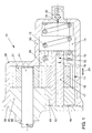
- a gear pump generally designated 10 shown in the form of an external gear pump.
- the gear pump 10 has Housing 38, which carries a cover 39 with pin 40.
- in the pin 40 is one Drive shaft 41 rotatably supported according to arrow 42.
- the drive shaft 41 is with a Drive gear 21 non-rotatably connected, which with an output gear 18 in intermeshing connection.
- the gear pump 10 is with a delivery-changing displacement unit 11 provided between a first Pressure chamber 12 and a second one, in addition to the displacement unit 11 acting compression spring 13 having pressure chamber 14 is slidably disposed.
- the displacement unit 11 is axially displaceable according to double arrow 25 and consists of an output shaft 17 and, each arranged coaxially on this, the output gear 18, a control piston 19 delimiting the first pressure chamber 12 and a second pressure chamber 14 delimiting spring piston 20.
- the driven gear 18 rotatably mounted on the output shaft 17, while the control piston 19 and Spring pistons 20 are pressed onto the same.
- the displacement unit 11 is in Dependence of a possibly occurring pressure difference between the first Pressure chamber 12 and the second pressure chamber 14 in relation to the non-axial slidable drive gear 21 slidable according to double arrow 25.
- the Pressure chambers 12, 14 are located by means of a pressure line 16 having a throttle 15 in hydraulic active connection.
- the throttle 15 is stepped, the second Pressure chamber 14 through-bore 22 with reduced cross section in the output shaft 17 educated.
- the second pressure chamber 14 is operatively connected to it by means of one standing pressure relief valve 32 in the form of a ball valve limited maximum pressure.
- the Pressure relief valve 32 is integrated in a wall 33 of the second pressure chamber 14 and has a wall wall 33 leading into the second pressure chamber 14, calibrated through hole 34.
- the control piston 19 engages with a corresponding recess in the pin 40, see above that an anti-rotation device for the displacement unit 11 is formed.
- FIG. 2 shows an alternative embodiment of the gear pump 10, the here Shift unit 11 in an axially shifted operating position according to double arrow 25 is shown.
- the throttle 15 is as Through hole 24 is formed in the spring piston 20 and is connected to the Tooth portion of the output gear 18 bordering pressure pocket 26 of the spring piston 20th in connection.
- the output shaft 17 is designed as a solid shaft.
- the Gear pump 10 according to FIG. 2 also has a second pressure chamber 14 in Operationally connected electro-hydraulic control unit 35.
- the control unit 35 is by means of a hydraulic line 37 and an intermediate, second Pressure relief valve 36 is operatively connected to the second pressure chamber 14.
- the Gear pump 10 thus has a first Pressure relief valve 32 for limiting the operating pressure in the second pressure chamber 14 to a maximum pressure and a second pressure relief valve 36 for determining a Control unit 35 activating minimum operating pressure in the second pressure chamber 14 on.
- the control unit 35 can be used to adjust the Pressure levels in the second pressure chamber 14 with a control unit, not shown be operatively connected, which with a by means of the gear pump 10th pressurized consumer unit (not shown) in connection.
- the gear pump 10 works according to the following principle: By having a throttle 15 There is a hydraulic pressure line 16 between the two pressure chambers 12, 14 Active connection. If the operating pressure in the second chamber 14 below the through the pressure relief valve 32 is the maximum pressure limit, consists in the Pressure chambers 12, 14 equal pressure, so that the displacement unit 11 due to the by means of the compression spring 13 continuously applied to the same compressive force In the basic position, in which the output gear 18 and the drive gear 21 comb with each other under full engagement width. This, a maximum The basic position of the displacement unit 11 that ensures the delivery rate is shown in FIG. 1 shown.
- the pressure relief valve 32 opens so that there is a pressure drop in the second pressure chamber 14 and thus to a pressure difference between the in hydraulic active connection standing chambers 12,14 comes. Because of this yourself setting pressure difference or that in the first pressure chamber 12 acting compressive force, which is symbolically shown in Figure 2 as arrows 43 results there is an axial displacement of the displacement unit with respect to the drive gear 21 11 in the direction of the second pressure chamber 14 according to the double arrow 25 smaller engagement width between the meshing gears 18, 21, so that the axial displacement of the displacement unit 11 in the direction of the second Pressure chamber 14 leads to a reduction in the delivery rate of the gear pump 10.
- the pressure pocket 26 provided in the embodiment according to FIG. 2 enables one advantageous flow of the fluid and reduces the present Lateral friction between the output gear 18 and the spring piston 20 Throttle 15 guiding pressure pocket 26, which is designed as a through bore 24, in the assembly of the spring piston 20 to be pressed onto the output shaft 17 as Serve fixing hole, so that in this way a position assignment of the pressure pocket 26th is possible.
- FIG. 3 shows an alternative embodiment of the spring piston 20 with respect to FIG. 2 in a schematic view from the driven gear side.
- the embodiment according to FIG. 3 does not guide the throttle 15 into a pressure pocket Spring piston 20 (pressure pocket 26 according to Figure 2), but borders directly on the Tooth area of the output gear 18.
- the diameter of the throttle 15 can be relatively be chosen large to take advantage of the control behavior in particular to achieve a cold, highly viscous fluid.
- An additional pressure pocket 26 and Suction pocket 28 of the spring piston 20 leads to advantages with regard to the fluid flow and between the driven gear 18 and the spring piston 20 Side friction.
- FIG. 4 shows a throttle 15 in a stepped Through hole 22 in the output shaft 17, which with an axially not Slidable throttle rod 29 with a tapered towards the second Pressure chamber 14 tapering throttle end in operative connection.
- the throttle rod 29 is not movable with one end on the housing 38 of the gear pump 10 fastened and penetrates the throttle 15 with its conical throttle end. In this way, the passage cross section of the throttle 15 is dependent on the changed axial displacement position of the displacement unit 11.
- the passage cross section is changed the throttle 15 uses the fluid operating temperature that arises in each case, which has a corresponding thermal expansion in operative connection with the throttle 15 standing throttle element 30 causes.
- a throttle element 30 can for example according to Figure 5 as an expansion rod preferably made of aluminum be formed, which with a in the direction of the second pressure chamber 14 tapering, conical throttle end 31 is provided with a narrowing of the in the output shaft 17 formed, stepped through bore 22 in the region of Throttle 15 is in operative connection.
- the output shaft 17 is preferably made of Steel made.
- the throttle element 30 is connected to the throttle 15 pioneering end fixed in the output shaft 17 and influenced with his conical throttle end 31 depending on the operating temperature the effective Passage cross section at throttle 15.
- the control piston 19 to reduce the friction on the peripheral surface and the associated Displacement inhibition of the displacement unit 11 a connecting channel in the form of a Connecting bore 51, which, starting from the first pressure chamber 12 on the Circumferential wall of the control piston 19 opens. Via this bore 51, the pressure in the pressure chamber 12 specifically to a specific area of the peripheral surface of the control piston 19 passed so as to reduce the undesirable lateral forces to reach.
- a connection channel between the second pressure chamber 14 and the peripheral wall of the spring piston 20 is provided there as a recess 53 or pocket in the peripheral wall of the spring piston 20 is trained.
- This recess guides the pressure of the second pressure chamber 14 laterally on the spring piston 20 so as to be able to compensate for undesired transverse forces.
- a through bore 55 is provided in the control piston 19 starting from the end face 57 which axially delimits the first pressure chamber 12 Control piston 19 penetrates completely and on the driven gear 18th neighboring face 59 emerges.
- the through hole 55 of Pressure from the first pressure chamber 12 into a wall area 63 of the output or Conveying gear 18 passed so that acting opposite to the gear mesh Hydraulic and tooth forces can be counteracted.
- housing bore 61 in the housing which e.g. at the level of the control piston 19 can be arranged and which leads away from the inside of the housing to the outside.
- the function of the Pressure relief valve 32 also from an electrically controllable, hydraulic control unit be taken over.
- a control unit is shown in FIG. 2 in addition to Pressure control valve 32 provided control unit 35 shown.
- the advantage of an electro-hydraulic The control unit lies in the freely adjustable at any time Delivery pressure level of the gear pump 10 according to the respective fluid pressure or Fluid quantity requirement of the unit to be supplied, for example an internal combustion engine to be supplied with oil.
- the applied engine oil pressure can be sensed electrically and according to the specification of an oil pressure map as a function of the engine speed and the oil temperature and a required engine function, such as the Circuit of a camshaft adjuster can be adjusted as required.
- the electrically controllable control unit can either be directly in a wall of the second pressure chamber of the gear pump 10 or with a hydraulic line the second pressure chamber of the gear pump is operatively connected to one be arranged elsewhere.
- a combination of an electrical Pressure control unit possible with mechanical-hydraulic pressure relief valves can be directly in a wall of the second pressure chamber of the gear pump 10 or with a hydraulic line the second pressure chamber of the gear pump is operatively connected to one be arranged elsewhere.
- FIG. 2 Such a combination is shown in Figure 2, the control system of Gear pump 10 for limiting the pressure in the second pressure chamber 14 operating pressure to a maximum pressure limit a first pressure relief valve 32 and is provided in parallel with an electrical control unit 35, which with the second pressure chamber 14 by means of the hydraulic line 37 and the second Pressure relief valve 36 is operatively connected.
- the control unit 35 is tailored to the needs pulsable or adjustable in cross-section to control a specific one Quantity of fluid from the second pressure chamber 14. In this way it is possible in the second pressure chamber 14 to set an operating pressure which is below the the first pressure relief valve 32 is predetermined maximum pressure.
- Control unit 35 connected in series second pressure relief valve 36 serves one Specify minimum pressure in the second pressure chamber 14 so that the electrical Pressure control by means of the control unit 35 only between a minimum fluid pressure of, for example, 2 bar by activating the second pressure relief valve 36 and one Maximum fluid pressure of 5 bar, for example, by activating the first pressure relief valve 32 acts.
- controllable gear pump according to the invention essentially corresponds to that Structure and function of the embodiments described in Figures 1 to 6 and therefore uses their reference numerals.
- the gear pump 10 now has a not shown there Helical teeth on the gears 21 and 18 through which the flow of oil to and can largely also take place radially from the tooth gaps of the gear wheels 21 and 18, so that additional oil pockets in the axially delimiting the gears 21 and 18 Chamber walls can be minimized, or can be completely eliminated.
- Axial oil pocket arranged at least on the pressure side, which is advantageous Way is arranged in the lid 39.
- This oil pocket is a groove 83 in the lid 39 formed, which over the entire length of the overlap with the pin 40th extends.
- This design of the groove acting as a pressure oil pocket has the advantage that the control stroke of the control piston 19 remains unaffected, since the rotary support of the control piston 19 on the wall of the pin 40 of the cover 39 over the entire Hub remains intact.
- a gear pump designed according to the above-described embodiments with flow control is used in a particularly advantageous manner as Oil pump of an internal combustion engine to be supplied with oil, since it largely a needs-based minimization of the oil production and the Oil pressure levels enabled and thus by a significantly reduced on average Oil pump drive power makes a notable contribution to the preferred reduction of the Fuel consumption of the internal combustion engine.
Landscapes
- Engineering & Computer Science (AREA)
- Mechanical Engineering (AREA)
- General Engineering & Computer Science (AREA)
- Details And Applications Of Rotary Liquid Pumps (AREA)
- Rotary Pumps (AREA)
Abstract
Description
- Figuren 1 und 2
- eine schematische, längsgeschnittene Seitenansicht zweier Ausführungsformen einer erfindungsgemäßen Zahnradpumpe;
- Figur 3
- eine schematische Vorderansicht einer quergeschnittenen, erfindungsgemäßen Zahnradpumpe gemäß einer weiteren Ausführungsform;
- Figuren 4 und 5
- eine schematische Darstellung einer erfindungsgemäßen, längsgeschnittenen Zahnradpumpe mit alternativ ausgebildeten Drosselhilfsmitteln,
- Figur 6
- eine weitere Ausführungsform, bei der Verbindungskanäle zwischen den Druckkammern und der Umfangswand der Verschiebeeinheit vorgesehen sind, und
- Figuren 7 und 8
- eine weitere Ausführungsform, bei der eine als Drucköltasche wirkende Nut in der Umfangswand des Deckels im Bereich der Überdeckung mit dem Steuerkolben angeordnet ist.
Claims (27)
- Zahnradpumpe mit einer fördermengenverändernden Verschiebeeinheit, die zwischen einer ersten Druckkammer und einer zweiten, eine zusätzlich auf die Verschiebeeinheit wirkende Druckfeder aufweisenden Druckkammer verschiebbar angeordnet ist, dadurch gekennzeichnet, dass die Druckkammern (12, 14) Mittels einer eine Drossel (15) aufweisenden Druckleitung (16) in hydraulischer Wirkverbindung stehen und die zweite Druckkammer (14) maximaldruckbegrenzt ist.
- Zahnradpumpe nach Anspruch 1, dadurch gekennzeichnet, dass die Zahnradpumpe (10) als Außenzahnradpumpe ausgebildet ist.
- Zahnradpumpe nach einem der vorhergehenden Ansprüche, dadurch gekennzeichnet, dass die Verschiebeeinheit (11) aus einer Abtriebswelle (17) und, jeweils auf dieser koaxial angeordnet, einem Abtriebszahnrad (18), einem die erste Druckkammer (12) begrenzenden Steuerkolben (19) und einem die zweite Druckkammer (14) begrenzenden Federkolben (20) besteht, wobei die Verschiebeeinheit (11) in Abhängigkeit einer eventuell sich einstellenden Druckdifferenz zwischen der ersten Druckkammer (12) und der zweiten Druckkammer (14) in Bezug auf ein Antriebszahnrad (21) verschiebbar ist.
- Zahnradpumpe nach einem der vorhergehenden Ansprüche, dadurch gekennzeichnet, dass die Drossel (15) als gestufte, zur zweiten Druckkammer (14) querschnittsreduzierte Durchgangsbohrung (22) in der Abtriebswelle (17) ausgebildet ist.
- Zahnradpumpe nach einem der vorhergehenden Ansprüche, dadurch gekennzeichnet, dass die Drossel (15) als stufenlose Durchgangsbohrung (23) in der Abtriebswelle (17) ausgebildet ist.
- Zahnradpumpe nach einem der vorhergehenden Ansprüche, dadurch gekennzeichnet, dass die Drossel (15) als Durchgangsbohrung (24) im Federkolben (20) ausgebildet ist und mit einer an den Zahnbereich des Abtriebszahnrads (18) grenzenden Drucktasche (26) des Federkolbens (20) in Verbindung steht.
- Zahnradpumpe nach einem der vorhergehenden Ansprüche, dadurch gekennzeichnet, dass die Drossel (15) als Durchgangsbohrung (24) im Federkolben (20) ausgebildet ist und die hydraulische Wirkverbindung zwischen der Drossel (15) und der ersten Druckkammer (12) periodisch durch einen jeweiligen Zahn (27) des drehbaren Abtriebszahnrads (18) unterbrechbar ist.
- Zahnradpumpe nach einem der vorhergehenden Ansprüche, dadurch gekennzeichnet, dass der Federkolben (20) eine an den Zahnbereich des Abtriebszahnrads (18) grenzende Saugtasche (28) aufweist.
- Zahnradpumpe nach einem der vorhergehenden Ansprüche, dadurch gekennzeichnet, dass die Drossel (15) einen veränderbaren Durchtrittsquerschnitt aufweist.
- Zahnradpumpe nach einem der vorhergehenden Ansprüche, dadurch gekennzeichnet, dass die Drossel (15) als Durchgangsbohrung (22) der Abtriebswelle (17) ausgebildet ist und von einer nicht verschiebbaren Drosselstange (29) mit sich zur zweiten Druckkammer (14) verkleinerndem Querschnitt durchdrungen ist.
- Zahnradpumpe nach einem der vorhergehenden Ansprüche, dadurch gekennzeichnet, dass der Durchtrittsquerschnitt der Drossel (15) in Abhängigkeit einer betriebstemperaturbedingten Wärmedehnung eines mit der Drossel (15) in Wirkverbindung stehenden Drosselelements (30) veränderbar ist.
- Zahnradpumpe nach einem der vorhergehenden Ansprüche, dadurch gekennzeichnet, dass das Drosselelement (30) als Dehnungsstange mit einem konisch sich verjüngenden, freien Drosselende (31) ausgebildet ist, welches bei einer positiven Wärmedehnung des Drosselelements (30) den Durchtrittsquerschnitt der Drossel (15) verringert.
- Zahnradpumpe nach einem der vorhergehenden Ansprüche, dadurch gekennzeichnet, dass zur Druckbegrenzung in der zweiten Druckkammer (14) ein mit dieser in Wirkverbindung stehendes Überdruckventil (32) vorgesehen ist.
- Zahnradpumpe nach einem der vorhergehenden Ansprüche, dadurch gekennzeichnet, dass das Überdruckventil (32) in einer Wandung (33) der zweiten Druckkammer (14) integriert ist und eine in der Wandung (33) ausgebildete, in die zweite Druckkammer (14) führende, kalibrierte Durchgangsbohrung (34) aufweist.
- Zahnradpumpe nach einem der vorhergehenden Ansprüche, dadurch gekennzeichnet, dass das Überdruckventil (32) als Kugelventil oder als Zungenventil ausgebildet ist.
- Zahnradpumpe nach einem der vorhergehenden Ansprüche, dadurch gekennzeichnet, dass zur Druckbegrenzung in der zweiten Druckkammer (14) eine mit dieser in Wirkverbindung stehende elektro-hydraulische Regeleinheit (35) vorgesehen ist.
- Zahnradpumpe nach einem der vorhergehenden Ansprüche, dadurch gekennzeichnet, dass zur bedarfsgerechten Einstellung des Druckniveaus in der zweiten Druckkammer (14) eine mit der Regeleinheit (35) wirkverbundene Steuereinheit vorgesehen ist, welche mit einem mittels der Zahnradpumpe druckbeaufschlagten Verbraucheraggregat in Verbindung steht.
- Zahnradpumpe nach einem der vorhergehenden Ansprüche, dadurch gekennzeichnet, dass die Regeleinheit (35) mit einem Überdruckventil (36) versehen ist.
- Zahnradpumpe nach einem der vorhergehenden Ansprüche, dadurch gekennzeichnet, dass das Antriebszahnrad (21) und das Abtriebszahnrad (18) jeweils eine Schrägverzahnung aufweisen.
- Zahnradpumpe nach einem der vorhergehenden Ansprüche, dadurch gekennzeichnet, dass die Verschiebeeinheit (11) Verbindungskanäle aufweist, die ausgehend von wenigstens einer der Druckkammern (12, 14) an die Umfangswand der Verschiebeeinheit münden.
- Zahnradpumpe nach Anspruch 20, dadurch gekennzeichnet, dass von der ersten Druckkammer (12) eine Verbindungsbohrung (51) im Steuerkolben (19) abführt, die an dessen Umfangsmantelfläche mündet.
- Zahnradpumpe nach Anspruch 20, dadurch gekennzeichnet, dass der Steuerkolben (19) eine Durchgangsbohrung (55) aufweist, die ausgehend von einer die erste Druckkammer (12) begrenzenden Stirnwand (57) in einen zwischen der Umfangswand des Abtriebszahnrades (18) und der Gehäuseinnenwand gebildeten Raum (63) einmündet.
- Zahnradpumpe nach Anspruch 20, dadurch gekennzeichnet, dass an der Umfangswand des Federkolbens (20) der Verschiebeeinheit (11) eine Ausnehmung (53) angeordnet ist, die in die zweite Druckkammer (14) einmündet.
- Zahnradpumpe nach einem der vorhergehenden Ansprüche, dadurch gekennzeichnet, dass eine von der Innenwand des die Verschiebeeinheit (11) aufnehmenden Gehäuses nach außen abführende Gehäusebohrung (61), vorzugsweise im Bereich des Steuerkolbens (19), vorgesehen ist.
- Zahnradpumpe nach Anspruch 1, dadurch gekennzeichnet, daß die Verzahnung des miteinander kämmenden Zahnradpaares als Schrägverzahnung ausgebildet ist.
- Zahnradpumpe nach Anspruch 1, dadurch gekennzeichnet, daß wenigstens eine der die Zahnräder (21, 18) axial begrenzenden Kammerwände eine Ausnehmung aufweist, die eine Tasche (83) für das Fördermedium, vorzugsweise Drucköl bildet.
- Zahnradpumpe nach Anspruch 26, dadurch gekennzeichnet, daß die Drucköltasche als Nut (83) in der Wand eines Gehäusedeckels (39) ausgebildet ist, die sich über die gesamte Länge der Überdeckung des Deckels (39) mit einer ersten Druckkammer (12) erstreckt.
Applications Claiming Priority (4)
| Application Number | Priority Date | Filing Date | Title |
|---|---|---|---|
| DE10010039 | 2000-03-02 | ||
| DE10010039 | 2000-03-02 | ||
| DE10043842A DE10043842A1 (de) | 2000-03-02 | 2000-09-06 | Zahnradpumpe mit einer fördermengenverändernden Verschiebeeinheit |
| DE10043842 | 2000-09-06 |
Publications (3)
| Publication Number | Publication Date |
|---|---|
| EP1130262A2 true EP1130262A2 (de) | 2001-09-05 |
| EP1130262A3 EP1130262A3 (de) | 2002-05-22 |
| EP1130262B1 EP1130262B1 (de) | 2007-12-19 |
Family
ID=26004623
Family Applications (1)
| Application Number | Title | Priority Date | Filing Date |
|---|---|---|---|
| EP01102128A Expired - Lifetime EP1130262B1 (de) | 2000-03-02 | 2001-02-01 | Zahnradpumpe mit einer fördermengenverändernden Verschiebeeinheit |
Country Status (3)
| Country | Link |
|---|---|
| EP (1) | EP1130262B1 (de) |
| AT (1) | ATE381675T1 (de) |
| DE (1) | DE50113387D1 (de) |
Cited By (6)
| Publication number | Priority date | Publication date | Assignee | Title |
|---|---|---|---|---|
| WO2003058071A1 (de) * | 2002-01-12 | 2003-07-17 | Dieter Voigt | Vorrichtung zur druckregelung von hydraulikpumpen |
| US6896489B2 (en) | 2000-12-12 | 2005-05-24 | Borgwarner Inc. | Variable displacement vane pump with variable target regulator |
| AT500629A1 (de) * | 2004-05-27 | 2006-02-15 | Tcg Unitech Ag | Zahnradpumpe |
| EP1832750A1 (de) | 2006-03-10 | 2007-09-12 | Schwäbische Hüttenwerke Automotive GmbH & Co. KG | Außenzahnradpumpe mit Entlastungstasche |
| WO2009129666A1 (zh) * | 2008-04-21 | 2009-10-29 | Feng Zhengmin | 液力汽车传动、差速机构及变腔式齿轮泵 |
| CN107940219A (zh) * | 2017-11-21 | 2018-04-20 | 吉林大学 | 可变排量齿轮式机油泵 |
Families Citing this family (4)
| Publication number | Priority date | Publication date | Assignee | Title |
|---|---|---|---|---|
| US7674095B2 (en) | 2000-12-12 | 2010-03-09 | Borgwarner Inc. | Variable displacement vane pump with variable target regulator |
| EP1350930B2 (de) | 2002-04-03 | 2016-01-27 | SLW Automotive Inc. | Regelbare Verdrängerpump sowie Steursystem dafür |
| US7726948B2 (en) | 2002-04-03 | 2010-06-01 | Slw Automotive Inc. | Hydraulic pump with variable flow and variable pressure and electric control |
| DE102013001750A1 (de) * | 2013-01-31 | 2014-07-31 | Volkswagen Aktiengesellschaft | Verfahren zur Regelung eines Öldrucks für einen Verbrennungsmotor sowie entsprechend ausgestaltete Ölpumpe |
Family Cites Families (4)
| Publication number | Priority date | Publication date | Assignee | Title |
|---|---|---|---|---|
| GB930913A (en) * | 1960-09-21 | 1963-07-10 | Serck Radiators Ltd | Rotary liquid pumps |
| FR1395842A (fr) * | 1964-03-06 | 1965-04-16 | Amélioration aux pompes à engrenages ordinaires ou à débit variable | |
| DE3347015A1 (de) * | 1983-12-24 | 1985-07-04 | Alfred Teves Gmbh, 6000 Frankfurt | Druckregelvorrichtung fuer eine hydraulikpumpe, insbesondere eine fluegelzellenpumpe |
| DE3528651A1 (de) * | 1985-08-09 | 1987-02-19 | Rohs Hans Guenther Prof Dr Ing | Zahnradpumpe |
-
2001
- 2001-02-01 DE DE50113387T patent/DE50113387D1/de not_active Expired - Lifetime
- 2001-02-01 AT AT01102128T patent/ATE381675T1/de not_active IP Right Cessation
- 2001-02-01 EP EP01102128A patent/EP1130262B1/de not_active Expired - Lifetime
Cited By (8)
| Publication number | Priority date | Publication date | Assignee | Title |
|---|---|---|---|---|
| US6896489B2 (en) | 2000-12-12 | 2005-05-24 | Borgwarner Inc. | Variable displacement vane pump with variable target regulator |
| WO2003058071A1 (de) * | 2002-01-12 | 2003-07-17 | Dieter Voigt | Vorrichtung zur druckregelung von hydraulikpumpen |
| AT500629A1 (de) * | 2004-05-27 | 2006-02-15 | Tcg Unitech Ag | Zahnradpumpe |
| AT500629B1 (de) * | 2004-05-27 | 2006-07-15 | Tcg Unitech Ag | Zahnradpumpe |
| EP1832750A1 (de) | 2006-03-10 | 2007-09-12 | Schwäbische Hüttenwerke Automotive GmbH & Co. KG | Außenzahnradpumpe mit Entlastungstasche |
| WO2009129666A1 (zh) * | 2008-04-21 | 2009-10-29 | Feng Zhengmin | 液力汽车传动、差速机构及变腔式齿轮泵 |
| CN107940219A (zh) * | 2017-11-21 | 2018-04-20 | 吉林大学 | 可变排量齿轮式机油泵 |
| CN107940219B (zh) * | 2017-11-21 | 2019-07-30 | 吉林大学 | 可变排量齿轮式机油泵 |
Also Published As
| Publication number | Publication date |
|---|---|
| DE50113387D1 (de) | 2008-01-31 |
| ATE381675T1 (de) | 2008-01-15 |
| EP1130262B1 (de) | 2007-12-19 |
| EP1130262A3 (de) | 2002-05-22 |
Similar Documents
| Publication | Publication Date | Title |
|---|---|---|
| DE10237801C5 (de) | Vorrichtung zur Druckregelung von Hydraulikpumpen | |
| DE3333647C2 (de) | Schmiermittelpumpe für die Druckerzeugung bei einem druckumlaufgeschmierten Verbrennungsmotor | |
| EP1363025B1 (de) | Verdrängerpumpe mit Fördervolumenverstellung | |
| DE10043842A1 (de) | Zahnradpumpe mit einer fördermengenverändernden Verschiebeeinheit | |
| EP3421802B1 (de) | Gaspumpe mit druckentlastung zur reduzierung des anfahrdrehmoments | |
| WO2006040090A1 (de) | Linearantrieb | |
| EP1462654B1 (de) | Zahnradpumpe | |
| EP1130262B1 (de) | Zahnradpumpe mit einer fördermengenverändernden Verschiebeeinheit | |
| EP1141551A1 (de) | Pumpenanordnung mit zwei hydropumpen | |
| EP1463888B1 (de) | Vorrichtung zur druckregelung von hydraulikpumpen | |
| DE4308506A1 (de) | Ölpumpensystem | |
| DE10033950C2 (de) | Pumpe mit Magnetkupplung | |
| EP1853824B1 (de) | Vorrichtung und verfahren zur schmierölversorgung | |
| EP0642430B1 (de) | Von einem verbrennungsmotor angetriebene hydraulikpumpe | |
| DE3716190A1 (de) | Schlupfregelsystem fuer die trennkupplung einer stroemungskupplung | |
| EP0225338B1 (de) | Regelpumpe | |
| EP1495227B1 (de) | Hydraulisches pumpenaggregat | |
| EP0509077B1 (de) | Kolbenpumpe, insbesondere radialkolbenpumpe | |
| DE4128543C2 (de) | ||
| DE102005028598B3 (de) | Regelbare Kühlmittelpumpe | |
| DE102009060188B4 (de) | Verstellventil für die Verstellung des Fördervolumens einer Verdrängerpumpe mit Kaltstartfunktion | |
| DE10223523B4 (de) | Vorrichtung zur Steuerung der Ventiltaktung | |
| EP1555436B1 (de) | Zahnradpumpe mit Fördermengenregelung | |
| AT500629B1 (de) | Zahnradpumpe | |
| DE102008041305A1 (de) | Hydraulikversorgungseinheit |
Legal Events
| Date | Code | Title | Description |
|---|---|---|---|
| PUAI | Public reference made under article 153(3) epc to a published international application that has entered the european phase |
Free format text: ORIGINAL CODE: 0009012 |
|
| AK | Designated contracting states |
Kind code of ref document: A2 Designated state(s): AT BE CH CY DE DK ES FI FR GB GR IE IT LI LU MC NL PT SE TR |
|
| AX | Request for extension of the european patent |
Free format text: AL;LT;LV;MK;RO;SI |
|
| PUAL | Search report despatched |
Free format text: ORIGINAL CODE: 0009013 |
|
| AX | Request for extension of the european patent |
Free format text: AL;LT;LV;MK;RO;SI |
|
| 17P | Request for examination filed |
Effective date: 20021122 |
|
| AKX | Designation fees paid |
Designated state(s): AT BE CH CY DE DK ES FI FR GB GR IE IT LI LU MC NL PT SE TR |
|
| 17Q | First examination report despatched |
Effective date: 20060721 |
|
| GRAP | Despatch of communication of intention to grant a patent |
Free format text: ORIGINAL CODE: EPIDOSNIGR1 |
|
| RIC1 | Information provided on ipc code assigned before grant |
Ipc: F04C 15/00 20060101AFI20070622BHEP |
|
| GRAS | Grant fee paid |
Free format text: ORIGINAL CODE: EPIDOSNIGR3 |
|
| GRAA | (expected) grant |
Free format text: ORIGINAL CODE: 0009210 |
|
| AK | Designated contracting states |
Kind code of ref document: B1 Designated state(s): AT BE CH CY DE DK ES FI FR GB GR IE IT LI LU MC NL PT SE TR |
|
| REG | Reference to a national code |
Ref country code: GB Ref legal event code: FG4D Free format text: NOT ENGLISH |
|
| REG | Reference to a national code |
Ref country code: IE Ref legal event code: FG4D Free format text: LANGUAGE OF EP DOCUMENT: GERMAN |
|
| REG | Reference to a national code |
Ref country code: CH Ref legal event code: EP |
|
| REF | Corresponds to: |
Ref document number: 50113387 Country of ref document: DE Date of ref document: 20080131 Kind code of ref document: P |
|
| GBT | Gb: translation of ep patent filed (gb section 77(6)(a)/1977) |
Effective date: 20080305 |
|
| PG25 | Lapsed in a contracting state [announced via postgrant information from national office to epo] |
Ref country code: SE Free format text: LAPSE BECAUSE OF FAILURE TO SUBMIT A TRANSLATION OF THE DESCRIPTION OR TO PAY THE FEE WITHIN THE PRESCRIBED TIME-LIMIT Effective date: 20080319 |
|
| PG25 | Lapsed in a contracting state [announced via postgrant information from national office to epo] |
Ref country code: FI Free format text: LAPSE BECAUSE OF FAILURE TO SUBMIT A TRANSLATION OF THE DESCRIPTION OR TO PAY THE FEE WITHIN THE PRESCRIBED TIME-LIMIT Effective date: 20071219 Ref country code: NL Free format text: LAPSE BECAUSE OF FAILURE TO SUBMIT A TRANSLATION OF THE DESCRIPTION OR TO PAY THE FEE WITHIN THE PRESCRIBED TIME-LIMIT Effective date: 20071219 |
|
| NLV1 | Nl: lapsed or annulled due to failure to fulfill the requirements of art. 29p and 29m of the patents act | ||
| ET | Fr: translation filed | ||
| PG25 | Lapsed in a contracting state [announced via postgrant information from national office to epo] |
Ref country code: ES Free format text: LAPSE BECAUSE OF FAILURE TO SUBMIT A TRANSLATION OF THE DESCRIPTION OR TO PAY THE FEE WITHIN THE PRESCRIBED TIME-LIMIT Effective date: 20080330 |
|
| BERE | Be: lapsed |
Owner name: VOLKSWAGEN A.G. Effective date: 20080228 |
|
| PG25 | Lapsed in a contracting state [announced via postgrant information from national office to epo] |
Ref country code: PT Free format text: LAPSE BECAUSE OF FAILURE TO SUBMIT A TRANSLATION OF THE DESCRIPTION OR TO PAY THE FEE WITHIN THE PRESCRIBED TIME-LIMIT Effective date: 20080519 |
|
| REG | Reference to a national code |
Ref country code: CH Ref legal event code: PL |
|
| REG | Reference to a national code |
Ref country code: IE Ref legal event code: FD4D |
|
| PLBE | No opposition filed within time limit |
Free format text: ORIGINAL CODE: 0009261 |
|
| STAA | Information on the status of an ep patent application or granted ep patent |
Free format text: STATUS: NO OPPOSITION FILED WITHIN TIME LIMIT |
|
| PG25 | Lapsed in a contracting state [announced via postgrant information from national office to epo] |
Ref country code: MC Free format text: LAPSE BECAUSE OF NON-PAYMENT OF DUE FEES Effective date: 20080228 Ref country code: LI Free format text: LAPSE BECAUSE OF NON-PAYMENT OF DUE FEES Effective date: 20080229 Ref country code: IE Free format text: LAPSE BECAUSE OF FAILURE TO SUBMIT A TRANSLATION OF THE DESCRIPTION OR TO PAY THE FEE WITHIN THE PRESCRIBED TIME-LIMIT Effective date: 20071219 Ref country code: CH Free format text: LAPSE BECAUSE OF NON-PAYMENT OF DUE FEES Effective date: 20080229 Ref country code: DK Free format text: LAPSE BECAUSE OF FAILURE TO SUBMIT A TRANSLATION OF THE DESCRIPTION OR TO PAY THE FEE WITHIN THE PRESCRIBED TIME-LIMIT Effective date: 20071219 |
|
| 26N | No opposition filed |
Effective date: 20080922 |
|
| PG25 | Lapsed in a contracting state [announced via postgrant information from national office to epo] |
Ref country code: GR Free format text: LAPSE BECAUSE OF FAILURE TO SUBMIT A TRANSLATION OF THE DESCRIPTION OR TO PAY THE FEE WITHIN THE PRESCRIBED TIME-LIMIT Effective date: 20080320 |
|
| PG25 | Lapsed in a contracting state [announced via postgrant information from national office to epo] |
Ref country code: BE Free format text: LAPSE BECAUSE OF NON-PAYMENT OF DUE FEES Effective date: 20080228 |
|
| PG25 | Lapsed in a contracting state [announced via postgrant information from national office to epo] |
Ref country code: AT Free format text: LAPSE BECAUSE OF NON-PAYMENT OF DUE FEES Effective date: 20080201 |
|
| PG25 | Lapsed in a contracting state [announced via postgrant information from national office to epo] |
Ref country code: CY Free format text: LAPSE BECAUSE OF FAILURE TO SUBMIT A TRANSLATION OF THE DESCRIPTION OR TO PAY THE FEE WITHIN THE PRESCRIBED TIME-LIMIT Effective date: 20071219 |
|
| PG25 | Lapsed in a contracting state [announced via postgrant information from national office to epo] |
Ref country code: LU Free format text: LAPSE BECAUSE OF NON-PAYMENT OF DUE FEES Effective date: 20080201 |
|
| PG25 | Lapsed in a contracting state [announced via postgrant information from national office to epo] |
Ref country code: TR Free format text: LAPSE BECAUSE OF FAILURE TO SUBMIT A TRANSLATION OF THE DESCRIPTION OR TO PAY THE FEE WITHIN THE PRESCRIBED TIME-LIMIT Effective date: 20071219 |
|
| PG25 | Lapsed in a contracting state [announced via postgrant information from national office to epo] |
Ref country code: IT Free format text: LAPSE BECAUSE OF NON-PAYMENT OF DUE FEES Effective date: 20080229 |
|
| PGFP | Annual fee paid to national office [announced via postgrant information from national office to epo] |
Ref country code: FR Payment date: 20130319 Year of fee payment: 13 Ref country code: DE Payment date: 20130228 Year of fee payment: 13 Ref country code: GB Payment date: 20130228 Year of fee payment: 13 |
|
| REG | Reference to a national code |
Ref country code: DE Ref legal event code: R119 Ref document number: 50113387 Country of ref document: DE |
|
| GBPC | Gb: european patent ceased through non-payment of renewal fee |
Effective date: 20140201 |
|
| REG | Reference to a national code |
Ref country code: FR Ref legal event code: ST Effective date: 20141031 |
|
| REG | Reference to a national code |
Ref country code: DE Ref legal event code: R119 Ref document number: 50113387 Country of ref document: DE Effective date: 20140902 |
|
| PG25 | Lapsed in a contracting state [announced via postgrant information from national office to epo] |
Ref country code: DE Free format text: LAPSE BECAUSE OF NON-PAYMENT OF DUE FEES Effective date: 20140902 Ref country code: GB Free format text: LAPSE BECAUSE OF NON-PAYMENT OF DUE FEES Effective date: 20140201 Ref country code: FR Free format text: LAPSE BECAUSE OF NON-PAYMENT OF DUE FEES Effective date: 20140228 |