EP1130448A1 - Dispositif de sûreté d'urgence pour aéronef - Google Patents
Dispositif de sûreté d'urgence pour aéronef Download PDFInfo
- Publication number
- EP1130448A1 EP1130448A1 EP01810056A EP01810056A EP1130448A1 EP 1130448 A1 EP1130448 A1 EP 1130448A1 EP 01810056 A EP01810056 A EP 01810056A EP 01810056 A EP01810056 A EP 01810056A EP 1130448 A1 EP1130448 A1 EP 1130448A1
- Authority
- EP
- European Patent Office
- Prior art keywords
- display
- safety device
- oxygen
- data
- flight safety
- Prior art date
- Legal status (The legal status is an assumption and is not a legal conclusion. Google has not performed a legal analysis and makes no representation as to the accuracy of the status listed.)
- Withdrawn
Links
- QVGXLLKOCUKJST-UHFFFAOYSA-N atomic oxygen Chemical compound [O] QVGXLLKOCUKJST-UHFFFAOYSA-N 0.000 claims abstract description 40
- 239000001301 oxygen Substances 0.000 claims abstract description 40
- 229910052760 oxygen Inorganic materials 0.000 claims abstract description 40
- 238000000746 purification Methods 0.000 claims abstract 2
- 230000004438 eyesight Effects 0.000 claims description 11
- 238000004891 communication Methods 0.000 claims description 3
- 230000002207 retinal effect Effects 0.000 claims description 2
- 230000035945 sensitivity Effects 0.000 claims description 2
- 230000003595 spectral effect Effects 0.000 claims description 2
- RZVHIXYEVGDQDX-UHFFFAOYSA-N 9,10-anthraquinone Chemical compound C1=CC=C2C(=O)C3=CC=CC=C3C(=O)C2=C1 RZVHIXYEVGDQDX-UHFFFAOYSA-N 0.000 claims 1
- 239000000779 smoke Substances 0.000 abstract description 18
- 231100000614 poison Toxicity 0.000 abstract 1
- 230000007096 poisonous effect Effects 0.000 abstract 1
- 101100269850 Caenorhabditis elegans mask-1 gene Proteins 0.000 description 12
- 230000029058 respiratory gaseous exchange Effects 0.000 description 8
- 238000013459 approach Methods 0.000 description 5
- 230000005540 biological transmission Effects 0.000 description 5
- 239000003517 fume Substances 0.000 description 3
- 238000000034 method Methods 0.000 description 3
- 230000008447 perception Effects 0.000 description 3
- 238000012545 processing Methods 0.000 description 3
- 230000000241 respiratory effect Effects 0.000 description 3
- 210000001525 retina Anatomy 0.000 description 3
- 230000000007 visual effect Effects 0.000 description 3
- 206010015946 Eye irritation Diseases 0.000 description 2
- 238000011109 contamination Methods 0.000 description 2
- 238000011161 development Methods 0.000 description 2
- 230000002708 enhancing effect Effects 0.000 description 2
- 231100000013 eye irritation Toxicity 0.000 description 2
- 238000001914 filtration Methods 0.000 description 2
- 230000006870 function Effects 0.000 description 2
- 210000003128 head Anatomy 0.000 description 2
- 239000004973 liquid crystal related substance Substances 0.000 description 2
- 239000000203 mixture Substances 0.000 description 2
- 230000006978 adaptation Effects 0.000 description 1
- 230000003247 decreasing effect Effects 0.000 description 1
- 230000001419 dependent effect Effects 0.000 description 1
- 238000005516 engineering process Methods 0.000 description 1
- 239000007789 gas Substances 0.000 description 1
- 238000005286 illumination Methods 0.000 description 1
- 238000003384 imaging method Methods 0.000 description 1
- 238000009434 installation Methods 0.000 description 1
- 230000010354 integration Effects 0.000 description 1
- 230000035987 intoxication Effects 0.000 description 1
- 231100000566 intoxication Toxicity 0.000 description 1
- 230000004297 night vision Effects 0.000 description 1
- 230000002265 prevention Effects 0.000 description 1
- 230000001681 protective effect Effects 0.000 description 1
- 210000002345 respiratory system Anatomy 0.000 description 1
- 231100000279 safety data Toxicity 0.000 description 1
- 238000007789 sealing Methods 0.000 description 1
- 239000000126 substance Substances 0.000 description 1
- 231100000331 toxic Toxicity 0.000 description 1
- 230000002588 toxic effect Effects 0.000 description 1
- 239000012780 transparent material Substances 0.000 description 1
Images


Classifications
-
- A—HUMAN NECESSITIES
- A62—LIFE-SAVING; FIRE-FIGHTING
- A62B—DEVICES, APPARATUS OR METHODS FOR LIFE-SAVING
- A62B18/00—Breathing masks or helmets, e.g. affording protection against chemical agents or for use at high altitudes or incorporating a pump or compressor for reducing the inhalation effort
- A62B18/08—Component parts for gas-masks or gas-helmets, e.g. windows, straps, speech transmitters, signal-devices
-
- A—HUMAN NECESSITIES
- A62—LIFE-SAVING; FIRE-FIGHTING
- A62B—DEVICES, APPARATUS OR METHODS FOR LIFE-SAVING
- A62B9/00—Component parts for respiratory or breathing apparatus
- A62B9/006—Indicators or warning devices, e.g. of low pressure, contamination
-
- B—PERFORMING OPERATIONS; TRANSPORTING
- B64—AIRCRAFT; AVIATION; COSMONAUTICS
- B64D—EQUIPMENT FOR FITTING IN OR TO AIRCRAFT; FLIGHT SUITS; PARACHUTES; ARRANGEMENT OR MOUNTING OF POWER PLANTS OR PROPULSION TRANSMISSIONS IN AIRCRAFT
- B64D25/00—Emergency apparatus or devices, not otherwise provided for
-
- G—PHYSICS
- G02—OPTICS
- G02B—OPTICAL ELEMENTS, SYSTEMS OR APPARATUS
- G02B27/00—Optical systems or apparatus not provided for by any of the groups G02B1/00 - G02B26/00, G02B30/00
- G02B27/01—Head-up displays
- G02B27/017—Head mounted
Definitions
- the present invention relates to an emergency flight safety device according to the preamble of claim 1.
- Information displaying methods fail to provide the pilot with the critical flight information data in certain emergency situations, especially in situations where smoke has developed.
- State of the art is either described as dedicated breathing equipment against nuclear, biological or chemical contamination (NBC protection equipment), as e.g. disclosed in U.S. Patent No. 4,741,332, or as improvement of a helmet mounted display by means of a specific cathode ray tube installation, as e.g. disclosed in EP-A-0 301 997.
- the European Patent Application publication 0 252 281 and the U.S. Patent No. 5,601,078 disclose a not specifically determined breathing apparatus that can be used underground or in non airborne embodiments. Attached to the breathing mask, on the outside, a removable, mask mounted monocular display is disclosed, capable of displaying measured data of low complexity with the help of a dedicated illumination system.
- Such a safety device should allow the wearer in emergency situations not only to have access to certain information but to indeed pilot an aircraft if the view is completely blurred and if the surrounding air is contaminated or toxic. It should, in addition, be possible to be made independent of the cockpit power supply in the case of a power failure or a deliberate switching off of the power supplies during emergency procedures.
- the emergency flight safety device comprises a full-face mask with a see-through, multifunctional display. It is fast to mount and therefore allows immediate control over the aircraft by the cockpit crew in the case of an emergency.
- the integration of the head-mounted display into the full-face mask prevents smoke from disturbing the clear perception of displayed information and avoids eye irritation. It provides an undisturbed vision and access to flight information data as well as safe breathing conditions.
- Each display area covers a substantial part of the person's field of vision. Therefore, from relevant data such as track, position, speed, altitude and the position of the aircraft in the tree dimensional space (inertial navigation data), the pilot can control the aircraft even if he does not see anything of the real world outside at all.
- this device is a first step to a virtual cockpit.
- the emergency flight safety device therefore further comprises an oxygen and air supply apparatus for supplying oxygen and/or air to the interior of the mask i.e. a powered purified air respiratory system which ensures that no intoxicated air gets into the mask.
- the multifunctional head-mounted display is structured into a virtual area where critical flight information data is displayed and an area where real data such as video images obtained by an external camera can be overlaid onto critical flight information data, enhancing the perception of an actual situation, especially in the final phase of an emergency landing.
- the emergency flight safety device described in the following is configured to be installed in an aircraft, namely an airplane.
- a full-face mask 1 belonging to the emergency flight safety device is illustrated in Figure 1 . It is mounted in an airplane cockpit, for instance contained in a dropout package, and can be automatically made available for the cockpit crew in case of an incident such as a sudden cabin-pressure loss, similar to the existing oxygen masks in airplanes.
- the full-face mask 1 is configured such as to effectively shield the entire face of a person 3, e.g., a crew member, from possibly intoxicated cockpit air. It covers essentially the whole face of the person 3 and has an elastically deformable margin section 5 for a smooth yet sealing skin contact. Straps 7 with adjustment buckles 9 serve as means for holding the mask on crew member's face.
- a view-through section 11 consists of transparent material and allows the person wearing the mask an essentially undisturbed perception under normal conditions, i.e., if the view in the cockpit is not blurred.
- a nose covering 12 divides the space between the mask 1 and the crew member's face into an viewing space and a breathing space which hermetically includes nose and mouth of the crew member.
- the mask 1 further comprises a purified air and oxygen supply joint 13 to which a conduit 14 is mounted.
- This conduit 14 is connected to valve means comprising an oxygen demand valve 15, which in turn is linked to at least one oxygen container and/or oxygen generator 16.
- the oxygen containers and/or the oxygen generator 16 are of the type used for passenger oxygen masks in existing airplanes.
- a pressure reducing valve 17 may be inserted between an oxygen container 16 and the oxygen demand valve 15.
- the oxygen demand valve 15 is further linked to a powered purified air respiratory device 18.
- This powered purified air respiratory device comprises filtering means 19 for the filtering of possibly intoxicated cabin air.
- the oxygen demand valve 15 is configured to switch between supplying the person wearing the mask with oxygen or purified air.
- the switching may be carried out manually, but the oxygen demand valve 15 may also comprise means for the switching to be carried out automatically, e.g. depending on the pressure loss in the cockpit.
- the oxygen demand valve may be configured such as to provide a mixture of oxygen and purified air, the mixing ratio depending on the cockpit air pressure.
- the conduit 14, the oxygen demand valve 15, the oxygen containers and/or the oxygen generator 16, the pressure reducing valve 17 and the powered purified air respiratory device 18 together constitute an oxygen and purified-air supply tool 14-18.
- Air and/or oxygen to be inhaled enters from said tool 14-18 through the purified air and oxygen supply joint 13 into the viewing space from where it gets through valves 21 into the breathing space.
- Air outlets 23 with valves allow the exhaled are to get to the outside.
- the view-through section 11 of the mask 1 comprises a see-through, multifunctional display 31.
- the emergency flight safety device is, as schematically shown in Figure 2 , preferably equipped with means 32 for the processing of flight data, e.g., a microprocessor or a computer.
- the flight data thus processed are submitted by control instruments such as a GPS/DGPS signal receiver 35, an inertial flight navigation system 36, an aircraft safety data controller 37 or a radio com interface 38.
- the emergency flight safety device also comprises means for the transmission of flight data from the data processing means 32 to the display 31, e.g., at least one transmission cable 33 connecting the microprocessor or computer 32 and the display 31, the cable 33 being preferably attached to the conduit 14.
- the display 31 is configured as a liquid-crystal display operated in a projection mode, using adjustable transmission. It preferably consists of two display areas 35, 37 which can be placed in front of and in close proximity to the left and the right eye of the person 3 wearing the mask 1, respectively. In this case, both display areas 35, 37 show essentially the same, slightly shifted display image, providing binocular vision.
- a Direct Laser Beam Writing on the Retina can be used.
- RSD technology is based on the principle that light from a light source with colour determining means is directly, or by an intermediate image, projected onto the retina.
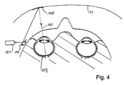
- a coloured light beam from a laser light source 101 placed behind a plane in front of the eye is projected onto an area with a semitransparent mirror 105 placed in close proximity in front of the eye.
- deflection means 103 two dimensional scanning is achieved.
- the reflected part 111 of the laser beam is projected onto the retina 113. In this way, an impression of an image covering an (effective) display area is created.
- the semitransparent mirror may, as an example be a part of or placed on the view through section 11.
- the mirrored area thus does not obstruct the person's vision.
- only one RSD set-up for the left eye only is shown.
- a RSD set-up for the right eye may be present. In this way, even a three dimensional impression can be created if required.
- the integrated display is an LCD display or if it is made up of a RSD set-up, it is important that the display areas cover a substantial part of the person's field of vision.
- the display area e.g. includes, if the person looks straight ahead, a central part of the field of vision and extends, as an example, from a region left of a vertical middle line to a region right of said vertical middle line.
- a substantial part is also covered if about 15%, preferably 25% or even at least 35% of the person's field of vision is covered by the display area if the person looks straight ahead.
- Two (real or effective) display areas 35, 37 together define one image for the observer 3, which is at least partially superposed to the actual view as seen by the observer 3 through the view-through section 11 of the mask 1 and which defines a virtual display area 41 as shown in Figure 3 .
- This virtual display area 41 is used to show GPS (Global Positioning System) and/or DGPS (Differential Global Positioning System) data 43 such as position, track, speed and altitude, giving information about the current position of the aircraft and its track to an emergency landing position.
- Flight safety system data 45 of the aircraft such as fire prevention information, power management conditions and communication frequencies may also be displayed in the virtual area 41 of the display 31.
- a center section 40 of the virtual display area 41 is preferably designed as a see-through section used to display data 47 produced by an inertial navigation system, informing the crew about the orientation of the aircraft in the three dimensional space similar to an artificial horizon.
- An external imaging device 34 e.g., a camera
- This camera 34 is preferably mounted on the bottom side of the airplane in a way that its field of vision is essentially equivalent to the field of vision of a person viewing through the cockpit window.
- the camera 34 is used to supply real time image data showing the ultimate landing situation, if necessary under enhanced night vision condition.
- the real time image data may also comprise runway lights, obstacles and/or visual glide path information (Visual Approach Slope Indicator, VASI or Precision Approach Path Indicator System PAPI).
- the image obtained by the camera 34 is shown on the same center section 40 of the virtual display area 41 as the inertial navigation system data 47.
- Other sensors such as speed or altitude sensors may form part of the emergency flight safety device in the same way as the camera 34.
- the data displayed on the virtual display area 41 depend on the situation, such as the light conditions, the cockpit atmosphere, etc.
- a flight-safety device that works efficiently in various emergency scenarios such as engine failure, fire, smoke, health-critical fume, electrical failure and also in deliberate actions under emergency conditions must be powered by a redundant power source that is independent of the main aircraft power source.
- the emergency flight safety device preferably has an auto-power function carried out by an independent and redundant power source 51 (see Fig. 2).
- the mask 1, the oxygen and purified air supply device 14-18 as well as the sensors such as GPS/DGPS 35, inertial navigation system 36, the aircraft safety system data controller 37, the radio com interface 38 and the outside camera 34 are included in this independent power management concept. If the sensors are also used by other applications than the emergency flight safety device, their redundant availability is assured by additional independent equipment.
- the means for transmitting data to the display does not have to comprise cables, it can also be equipped with a radio or similar transmission apparatus.
- communication equipment such as a headset and a microphone can be integrated in or attached to the full-face mask 1.
- the mask 1 can further comprise means for the adaptation of the display positioning to the crew member's head size. The crew member's data may even be stored in the computer belonging to the transmission tool so that the exact positioning of the two display areas 35, 37 on the mask 1 can be automatically adapted to the eye position and spacing.
- the emergency flight safety device may further be equipped with intelligent means for the matching of the gas composition in the mask to the crew member's needs, which means may comprise sensors mounted on the inside of the full-face mask 1.
Landscapes
- Health & Medical Sciences (AREA)
- Business, Economics & Management (AREA)
- Emergency Management (AREA)
- Pulmonology (AREA)
- General Health & Medical Sciences (AREA)
- Physics & Mathematics (AREA)
- Engineering & Computer Science (AREA)
- Aviation & Aerospace Engineering (AREA)
- General Physics & Mathematics (AREA)
- Optics & Photonics (AREA)
- Respiratory Apparatuses And Protective Means (AREA)
Priority Applications (1)
| Application Number | Priority Date | Filing Date | Title |
|---|---|---|---|
| EP01810056A EP1130448A1 (fr) | 2000-02-01 | 2001-01-22 | Dispositif de sûreté d'urgence pour aéronef |
Applications Claiming Priority (3)
| Application Number | Priority Date | Filing Date | Title |
|---|---|---|---|
| EP00101939 | 2000-02-01 | ||
| EP00101939A EP1121959A1 (fr) | 2000-02-01 | 2000-02-01 | Dispositif de sûreté d'urgence pour aéronef |
| EP01810056A EP1130448A1 (fr) | 2000-02-01 | 2001-01-22 | Dispositif de sûreté d'urgence pour aéronef |
Publications (1)
| Publication Number | Publication Date |
|---|---|
| EP1130448A1 true EP1130448A1 (fr) | 2001-09-05 |
Family
ID=26070486
Family Applications (1)
| Application Number | Title | Priority Date | Filing Date |
|---|---|---|---|
| EP01810056A Withdrawn EP1130448A1 (fr) | 2000-02-01 | 2001-01-22 | Dispositif de sûreté d'urgence pour aéronef |
Country Status (1)
| Country | Link |
|---|---|
| EP (1) | EP1130448A1 (fr) |
Cited By (4)
| Publication number | Priority date | Publication date | Assignee | Title |
|---|---|---|---|---|
| EP1402305A4 (fr) * | 2001-07-02 | 2007-10-03 | Be Intellectual Pty Inc | Masque de visualisation pour equipage d'aeronef avec dispositif d'affichage d'instruments de bord par balayage retinien pour situations d'urgence avec fumee dans le cockpit |
| WO2009027574A1 (fr) * | 2007-08-31 | 2009-03-05 | Savox Communications Oy Ab (Ltd) | Procédé et agencement pour présenter des informations sous forme visuelle |
| FR2924213A1 (fr) * | 2007-11-27 | 2009-05-29 | Thales Sa | Instrument de secours pour aeronef comportant les fonctions de controle radio et systeme de gestion de vol associe |
| US12415098B2 (en) * | 2021-05-25 | 2025-09-16 | Blue Tron Technologies Inc. | Reusable purified air breathing device with a retractable display screen |
Citations (7)
| Publication number | Priority date | Publication date | Assignee | Title |
|---|---|---|---|---|
| EP0252281A1 (fr) | 1986-07-02 | 1988-01-13 | Drägerwerk Aktiengesellschaft | Appareil de protection respiratoire comportant un dispositif de traitement des signaux |
| US4741332A (en) | 1984-02-15 | 1988-05-03 | Intertechnique | Equipment for protecting personnel from contamination |
| EP0301997A2 (fr) | 1987-07-30 | 1989-02-01 | United Technologies Corporation | Méthode et appareil pour le montage d'un T.R.C. pour système de visualisation à tête-haute |
| US5115804A (en) | 1987-08-05 | 1992-05-26 | Dme Corporation | Protective hood and oral-nasal mask |
| EP0562742A1 (fr) * | 1992-03-25 | 1993-09-29 | Motorola, Inc. | Affichage à balayage direct à la rétine |
| JPH08317318A (ja) * | 1995-05-22 | 1996-11-29 | Galaxy:Kk | 情報伝達装置 |
| US5601078A (en) | 1994-07-16 | 1997-02-11 | Dragerwerk Ag | Breathing apparatus with a display unit |
-
2001
- 2001-01-22 EP EP01810056A patent/EP1130448A1/fr not_active Withdrawn
Patent Citations (7)
| Publication number | Priority date | Publication date | Assignee | Title |
|---|---|---|---|---|
| US4741332A (en) | 1984-02-15 | 1988-05-03 | Intertechnique | Equipment for protecting personnel from contamination |
| EP0252281A1 (fr) | 1986-07-02 | 1988-01-13 | Drägerwerk Aktiengesellschaft | Appareil de protection respiratoire comportant un dispositif de traitement des signaux |
| EP0301997A2 (fr) | 1987-07-30 | 1989-02-01 | United Technologies Corporation | Méthode et appareil pour le montage d'un T.R.C. pour système de visualisation à tête-haute |
| US5115804A (en) | 1987-08-05 | 1992-05-26 | Dme Corporation | Protective hood and oral-nasal mask |
| EP0562742A1 (fr) * | 1992-03-25 | 1993-09-29 | Motorola, Inc. | Affichage à balayage direct à la rétine |
| US5601078A (en) | 1994-07-16 | 1997-02-11 | Dragerwerk Ag | Breathing apparatus with a display unit |
| JPH08317318A (ja) * | 1995-05-22 | 1996-11-29 | Galaxy:Kk | 情報伝達装置 |
Non-Patent Citations (1)
| Title |
|---|
| PATENT ABSTRACTS OF JAPAN vol. 1997, no. 03 31 March 1997 (1997-03-31) * |
Cited By (4)
| Publication number | Priority date | Publication date | Assignee | Title |
|---|---|---|---|---|
| EP1402305A4 (fr) * | 2001-07-02 | 2007-10-03 | Be Intellectual Pty Inc | Masque de visualisation pour equipage d'aeronef avec dispositif d'affichage d'instruments de bord par balayage retinien pour situations d'urgence avec fumee dans le cockpit |
| WO2009027574A1 (fr) * | 2007-08-31 | 2009-03-05 | Savox Communications Oy Ab (Ltd) | Procédé et agencement pour présenter des informations sous forme visuelle |
| FR2924213A1 (fr) * | 2007-11-27 | 2009-05-29 | Thales Sa | Instrument de secours pour aeronef comportant les fonctions de controle radio et systeme de gestion de vol associe |
| US12415098B2 (en) * | 2021-05-25 | 2025-09-16 | Blue Tron Technologies Inc. | Reusable purified air breathing device with a retractable display screen |
Similar Documents
| Publication | Publication Date | Title |
|---|---|---|
| US6675800B2 (en) | Emergency flight safety device | |
| US6714141B2 (en) | Electronic cockpit vision system | |
| EP3077868B1 (fr) | Système et procédé d'amélioration de la vision à l'intérieur du cockpit d'un avion | |
| US6297749B1 (en) | Emergency operating system for piloting an aircraft in a smoke filled cockpit | |
| EP2229673B1 (fr) | Appareil électro-optique de vision d'urgence | |
| CA2691375C (fr) | Aide a l'atterrissage pour aeronef | |
| CA2060406C (fr) | Systeme d'affichage d'images virtuelles a contours structurels | |
| US20180304107A1 (en) | Protective system for aircraft pilot | |
| EP1046411A2 (fr) | Un casque | |
| CN104053478A (zh) | 驾驶舱紧急装置 | |
| US20250258380A1 (en) | Heads-up Display Apparatus for use During a Smoke Emergency | |
| EP1402305B1 (fr) | Masque de visualisation pour equipage d'aeronef avec dispositif d'affichage d'instruments de bord par balayage retinien pour situations d'urgence avec fumee dans le cockpit | |
| EP1130448A1 (fr) | Dispositif de sûreté d'urgence pour aéronef | |
| Lemoine et al. | Contribution of TopOwl head mounted display system in degraded visual environments | |
| Keller | Cockpit emergency safety system | |
| HK1229894B (en) | System and method for enhancing vision inside an aircraft cockpit | |
| HK1153303B (en) | Electro-optical emergency vision apparatus | |
| FR2802895A1 (fr) | Systeme secours de pilotage, a mise en place rapide, en presence de fumees cabine |
Legal Events
| Date | Code | Title | Description |
|---|---|---|---|
| PUAI | Public reference made under article 153(3) epc to a published international application that has entered the european phase |
Free format text: ORIGINAL CODE: 0009012 |
|
| AK | Designated contracting states |
Kind code of ref document: A1 Designated state(s): AT BE CH CY DE DK ES FI FR GB GR IE IT LI LU MC NL PT SE TR Kind code of ref document: A1 Designated state(s): CH DE ES FR GB LI |
|
| AX | Request for extension of the european patent |
Free format text: AL;LT;LV;MK;RO;SI |
|
| AKX | Designation fees paid |
Free format text: AT BE CH CY DE LI |
|
| RBV | Designated contracting states (corrected) |
Designated state(s): CH DE ES FR GB LI |
|
| 17P | Request for examination filed |
Effective date: 20020212 |
|
| RBV | Designated contracting states (corrected) |
Designated state(s): AT BE CH CY DE LI |
|
| RBV | Designated contracting states (corrected) |
Designated state(s): CH DE ES FR GB LI |
|
| 17Q | First examination report despatched |
Effective date: 20040413 |
|
| STAA | Information on the status of an ep patent application or granted ep patent |
Free format text: STATUS: THE APPLICATION IS DEEMED TO BE WITHDRAWN |
|
| 18D | Application deemed to be withdrawn |
Effective date: 20060801 |