EP1130583A1 - Verfahren und Vorrichtung zur optischen Aufzeichnung, und optisches Speichermedium - Google Patents
Verfahren und Vorrichtung zur optischen Aufzeichnung, und optisches Speichermedium Download PDFInfo
- Publication number
- EP1130583A1 EP1130583A1 EP01104495A EP01104495A EP1130583A1 EP 1130583 A1 EP1130583 A1 EP 1130583A1 EP 01104495 A EP01104495 A EP 01104495A EP 01104495 A EP01104495 A EP 01104495A EP 1130583 A1 EP1130583 A1 EP 1130583A1
- Authority
- EP
- European Patent Office
- Prior art keywords
- pulse width
- end portion
- medium
- write
- pulse
- Prior art date
- Legal status (The legal status is an assumption and is not a legal conclusion. Google has not performed a legal analysis and makes no representation as to the accuracy of the status listed.)
- Ceased
Links
- 230000003287 optical effect Effects 0.000 title claims abstract description 109
- 238000000034 method Methods 0.000 title claims abstract description 55
- 238000003860 storage Methods 0.000 title claims abstract description 51
- 239000000463 material Substances 0.000 claims description 28
- 238000012360 testing method Methods 0.000 claims description 10
- 230000008569 process Effects 0.000 claims description 5
- 239000010410 layer Substances 0.000 description 76
- 239000012782 phase change material Substances 0.000 description 17
- 238000002310 reflectometry Methods 0.000 description 14
- 229920005989 resin Polymers 0.000 description 13
- 239000011347 resin Substances 0.000 description 13
- 239000000758 substrate Substances 0.000 description 13
- 238000002474 experimental method Methods 0.000 description 10
- 239000011241 protective layer Substances 0.000 description 10
- 238000010586 diagram Methods 0.000 description 7
- 239000000203 mixture Substances 0.000 description 6
- 230000015572 biosynthetic process Effects 0.000 description 5
- 230000005855 radiation Effects 0.000 description 5
- 238000004544 sputter deposition Methods 0.000 description 4
- 229910000763 AgInSbTe Inorganic materials 0.000 description 3
- 239000004698 Polyethylene Substances 0.000 description 3
- 229910045601 alloy Inorganic materials 0.000 description 3
- 239000000956 alloy Substances 0.000 description 3
- 229910052782 aluminium Inorganic materials 0.000 description 3
- 229910052799 carbon Inorganic materials 0.000 description 3
- 238000001723 curing Methods 0.000 description 3
- 230000007423 decrease Effects 0.000 description 3
- 229910052737 gold Inorganic materials 0.000 description 3
- 238000010438 heat treatment Methods 0.000 description 3
- 238000005259 measurement Methods 0.000 description 3
- 229910052763 palladium Inorganic materials 0.000 description 3
- 229910052710 silicon Inorganic materials 0.000 description 3
- 229910052718 tin Inorganic materials 0.000 description 3
- 229920000178 Acrylic resin Polymers 0.000 description 2
- 239000004925 Acrylic resin Substances 0.000 description 2
- VYPSYNLAJGMNEJ-UHFFFAOYSA-N Silicium dioxide Chemical compound O=[Si]=O VYPSYNLAJGMNEJ-UHFFFAOYSA-N 0.000 description 2
- GWEVSGVZZGPLCZ-UHFFFAOYSA-N Titan oxide Chemical compound O=[Ti]=O GWEVSGVZZGPLCZ-UHFFFAOYSA-N 0.000 description 2
- XLOMVQKBTHCTTD-UHFFFAOYSA-N Zinc monoxide Chemical compound [Zn]=O XLOMVQKBTHCTTD-UHFFFAOYSA-N 0.000 description 2
- MCMNRKCIXSYSNV-UHFFFAOYSA-N Zirconium dioxide Chemical compound O=[Zr]=O MCMNRKCIXSYSNV-UHFFFAOYSA-N 0.000 description 2
- 230000008859 change Effects 0.000 description 2
- 238000005229 chemical vapour deposition Methods 0.000 description 2
- 229910052804 chromium Inorganic materials 0.000 description 2
- 238000007796 conventional method Methods 0.000 description 2
- 230000006866 deterioration Effects 0.000 description 2
- 239000003989 dielectric material Substances 0.000 description 2
- 230000006872 improvement Effects 0.000 description 2
- 239000012535 impurity Substances 0.000 description 2
- 238000007733 ion plating Methods 0.000 description 2
- 238000002844 melting Methods 0.000 description 2
- 230000008018 melting Effects 0.000 description 2
- 238000012544 monitoring process Methods 0.000 description 2
- 238000000465 moulding Methods 0.000 description 2
- 238000005240 physical vapour deposition Methods 0.000 description 2
- 229920005668 polycarbonate resin Polymers 0.000 description 2
- 239000004431 polycarbonate resin Substances 0.000 description 2
- -1 polypropylene Polymers 0.000 description 2
- LIVNPJMFVYWSIS-UHFFFAOYSA-N silicon monoxide Chemical compound [Si-]#[O+] LIVNPJMFVYWSIS-UHFFFAOYSA-N 0.000 description 2
- 239000000126 substance Substances 0.000 description 2
- XOLBLPGZBRYERU-UHFFFAOYSA-N tin dioxide Chemical compound O=[Sn]=O XOLBLPGZBRYERU-UHFFFAOYSA-N 0.000 description 2
- 229910052719 titanium Inorganic materials 0.000 description 2
- YOIDHZBOHMNTNP-UHFFFAOYSA-N 1-(4-chlorophenyl)-3-(4-methylphenyl)sulfonylurea Chemical compound C1=CC(C)=CC=C1S(=O)(=O)NC(=O)NC1=CC=C(Cl)C=C1 YOIDHZBOHMNTNP-UHFFFAOYSA-N 0.000 description 1
- 229910017083 AlN Inorganic materials 0.000 description 1
- OKTJSMMVPCPJKN-UHFFFAOYSA-N Carbon Chemical compound [C] OKTJSMMVPCPJKN-UHFFFAOYSA-N 0.000 description 1
- YCKRFDGAMUMZLT-UHFFFAOYSA-N Fluorine atom Chemical compound [F] YCKRFDGAMUMZLT-UHFFFAOYSA-N 0.000 description 1
- 229910005900 GeTe Inorganic materials 0.000 description 1
- 229910005918 GeTeSe Inorganic materials 0.000 description 1
- 239000004743 Polypropylene Substances 0.000 description 1
- 229910018219 SeTe Inorganic materials 0.000 description 1
- 229910052581 Si3N4 Inorganic materials 0.000 description 1
- XUIMIQQOPSSXEZ-UHFFFAOYSA-N Silicon Chemical compound [Si] XUIMIQQOPSSXEZ-UHFFFAOYSA-N 0.000 description 1
- ATJFFYVFTNAWJD-UHFFFAOYSA-N Tin Chemical compound [Sn] ATJFFYVFTNAWJD-UHFFFAOYSA-N 0.000 description 1
- 229920000122 acrylonitrile butadiene styrene Polymers 0.000 description 1
- 239000004676 acrylonitrile butadiene styrene Substances 0.000 description 1
- XAGFODPZIPBFFR-UHFFFAOYSA-N aluminium Chemical compound [Al] XAGFODPZIPBFFR-UHFFFAOYSA-N 0.000 description 1
- 229910052796 boron Inorganic materials 0.000 description 1
- QHIWVLPBUQWDMQ-UHFFFAOYSA-N butyl prop-2-enoate;methyl 2-methylprop-2-enoate;prop-2-enoic acid Chemical compound OC(=O)C=C.COC(=O)C(C)=C.CCCCOC(=O)C=C QHIWVLPBUQWDMQ-UHFFFAOYSA-N 0.000 description 1
- 239000000919 ceramic Substances 0.000 description 1
- 229910052681 coesite Inorganic materials 0.000 description 1
- 238000001816 cooling Methods 0.000 description 1
- 229910052802 copper Inorganic materials 0.000 description 1
- 229910052906 cristobalite Inorganic materials 0.000 description 1
- 238000002425 crystallisation Methods 0.000 description 1
- 230000008025 crystallization Effects 0.000 description 1
- 238000007598 dipping method Methods 0.000 description 1
- 238000001227 electron beam curing Methods 0.000 description 1
- 239000003822 epoxy resin Substances 0.000 description 1
- 238000011156 evaluation Methods 0.000 description 1
- 239000011737 fluorine Substances 0.000 description 1
- 229910052731 fluorine Inorganic materials 0.000 description 1
- 229910052732 germanium Inorganic materials 0.000 description 1
- 239000011521 glass Substances 0.000 description 1
- LNEPOXFFQSENCJ-UHFFFAOYSA-N haloperidol Chemical compound C1CC(O)(C=2C=CC(Cl)=CC=2)CCN1CCCC(=O)C1=CC=C(F)C=C1 LNEPOXFFQSENCJ-UHFFFAOYSA-N 0.000 description 1
- 229910052742 iron Inorganic materials 0.000 description 1
- 229910052748 manganese Inorganic materials 0.000 description 1
- 229910052751 metal Inorganic materials 0.000 description 1
- 239000002184 metal Substances 0.000 description 1
- 150000001247 metal acetylides Chemical class 0.000 description 1
- 150000002739 metals Chemical class 0.000 description 1
- 238000012986 modification Methods 0.000 description 1
- 230000004048 modification Effects 0.000 description 1
- 229910052759 nickel Inorganic materials 0.000 description 1
- 150000004767 nitrides Chemical class 0.000 description 1
- 229910052757 nitrogen Inorganic materials 0.000 description 1
- 229910052760 oxygen Inorganic materials 0.000 description 1
- 229910052698 phosphorus Inorganic materials 0.000 description 1
- 229910052697 platinum Inorganic materials 0.000 description 1
- 229920002285 poly(styrene-co-acrylonitrile) Polymers 0.000 description 1
- 229920000647 polyepoxide Polymers 0.000 description 1
- 229920013716 polyethylene resin Polymers 0.000 description 1
- 229920001155 polypropylene Polymers 0.000 description 1
- 229920005990 polystyrene resin Polymers 0.000 description 1
- 238000002360 preparation method Methods 0.000 description 1
- 238000012545 processing Methods 0.000 description 1
- 230000004044 response Effects 0.000 description 1
- 230000000717 retained effect Effects 0.000 description 1
- 229910052711 selenium Inorganic materials 0.000 description 1
- FESBVLZDDCQLFY-UHFFFAOYSA-N sete Chemical compound [Te]=[Se] FESBVLZDDCQLFY-UHFFFAOYSA-N 0.000 description 1
- 239000010703 silicon Substances 0.000 description 1
- 239000000377 silicon dioxide Substances 0.000 description 1
- 229910052709 silver Inorganic materials 0.000 description 1
- 229910052682 stishovite Inorganic materials 0.000 description 1
- 229910052717 sulfur Inorganic materials 0.000 description 1
- 229920002803 thermoplastic polyurethane Polymers 0.000 description 1
- 150000003568 thioethers Chemical class 0.000 description 1
- 239000012780 transparent material Substances 0.000 description 1
- 229910052905 tridymite Inorganic materials 0.000 description 1
- 229910052720 vanadium Inorganic materials 0.000 description 1
- 229910052725 zinc Inorganic materials 0.000 description 1
- 229910052726 zirconium Inorganic materials 0.000 description 1
Images


Classifications
-
- G—PHYSICS
- G11—INFORMATION STORAGE
- G11B—INFORMATION STORAGE BASED ON RELATIVE MOVEMENT BETWEEN RECORD CARRIER AND TRANSDUCER
- G11B7/00—Recording or reproducing by optical means, e.g. recording using a thermal beam of optical radiation by modifying optical properties or the physical structure, reproducing using an optical beam at lower power by sensing optical properties; Record carriers therefor
- G11B7/004—Recording, reproducing or erasing methods; Read, write or erase circuits therefor
- G11B7/006—Overwriting
- G11B7/0062—Overwriting strategies, e.g. recording pulse sequences with erasing level used for phase-change media
-
- G—PHYSICS
- G11—INFORMATION STORAGE
- G11B—INFORMATION STORAGE BASED ON RELATIVE MOVEMENT BETWEEN RECORD CARRIER AND TRANSDUCER
- G11B7/00—Recording or reproducing by optical means, e.g. recording using a thermal beam of optical radiation by modifying optical properties or the physical structure, reproducing using an optical beam at lower power by sensing optical properties; Record carriers therefor
- G11B7/004—Recording, reproducing or erasing methods; Read, write or erase circuits therefor
- G11B7/0045—Recording
-
- G—PHYSICS
- G11—INFORMATION STORAGE
- G11B—INFORMATION STORAGE BASED ON RELATIVE MOVEMENT BETWEEN RECORD CARRIER AND TRANSDUCER
- G11B7/00—Recording or reproducing by optical means, e.g. recording using a thermal beam of optical radiation by modifying optical properties or the physical structure, reproducing using an optical beam at lower power by sensing optical properties; Record carriers therefor
- G11B7/12—Heads, e.g. forming of the optical beam spot or modulation of the optical beam
- G11B7/125—Optical beam sources therefor, e.g. laser control circuitry specially adapted for optical storage devices; Modulators, e.g. means for controlling the size or intensity of optical spots or optical traces
- G11B7/126—Circuits, methods or arrangements for laser control or stabilisation
Definitions
- the present invention relates to an optical recording method and apparatus that records information onto an optical storage medium at a high speed by emitting a light beam to a recording layer of the storage medium. Further, the present invention relates to an optical storage medium that stores information recorded by using the optical recording method and apparatus.
- optical storage media including CD-R (compact disk recordable), CD-RW (compact disk rewritable) and so on, become widespread.
- Each storage medium is provided for recording information thereon by focusing a light beam onto a recording layer of the medium and changing the phase of the recording layer material.
- an optical recording method that records information onto a recording layer of an optical recording medium by emitting light to the recording layer of the medium.
- a light source driving waveform is applied to a light source to control emission of a light beam to the recording layer of the medium based on a write data modulation method.
- an optical recording method that determines an optimum light source driving waveform (including the write power and the write pulse width), which is applied to the light source, based on a readout signal of the recorded information derived from a reflection light beam from the optical disk.
- a pulse width modulation (PWM) method is utilized for application of a multi-pulse light source driving waveform to the light source to control emission of a light beam from the light source to a rewritable phase-change optical disk having a recording layer with a large crystallization speed.
- PWM pulse width modulation
- the conventional method provides the driving waveform that is effective in recording a long amorphous mark on the recording layer of the optical disk.
- Japanese Laid-Open Patent Application No.63-266633 and United States Patent No.5150352 disclose an optical recording method which eliminates positional variations of a mark edge and improves the jitter characteristics of an optical disk by applying a driving waveform including a front-end portion or a tail-end portion having an increased pulse width or with an increased power level to the light source.
- the rewritable compact disk standards (the orange book, part III, ver. 2.0) provide the recommended specifications of 1X to 4X linear velocity recording of the rewritable recording media.
- the linear velocities 1X to 4X according to the standards range from 1.2 m/s to 5.6 m/s.
- the recording speeds of the media in this range require a relatively long time to record information onto the media.
- Preparations of high-speed specifications of 4X to 10X linear velocity recording for the rewritable compact disk standards are now under way.
- the linear velocities 4X to 10X according to the standards range from 5 m/s to 28 m/s.
- Another object of the present invention is to provide an optical recording method and apparatus that ensures good write/erase characteristics of the rewritable phase-change medium and retains the compatibility with the write-once storage medium when high-speed recording is performed.
- Another object of the present invention is to provide an optical recording method and apparatus that provides increases of initial characteristics and overwrite performance of the rewritable phase-change medium.
- Another object of the present invention is to provide an optical storage medium that stores information recorded by using the optical recording method and apparatus such that good write/erase characteristics of the rewritable phase-change medium are ensured and the compatibility with the write-once storage medium is retained when high-speed recording is performed.
- an optical recording method which records a sequence of data blocks onto a recording layer of an optical recording medium by emitting light to the recording layer of the medium and changing a phase of a recording material of the recording layer, the method comprising the steps of: applying a light source driving power to a light source to control emission of a light beam to the recording layer of the medium, the driving power including a sequence of mark and space portions, each mark potion having a pulse width that corresponds to a multiple of a period T of a write clock based on a write data modulation method; setting a multi-pulse waveform of each mark portion of the driving power that includes a front-end portion, a multi-pulse portion and a tail-end portion, the front-end portion having a first pulse width t1 with a high-power write level Pw and starting from a middle-power erase level Pe, the multi-pulse portion including a sequence of write pulses each having a second pulse width t2 with the
- an optical recording apparatus which records a sequence of data blocks onto a recording layer of an optical recording medium by emitting light to the recording layer of the medium and changing a phase of a recording material of the recording layer
- the apparatus comprising: a light source driver unit which applies a light source driving power to a light source to control emission of a light beam to the recording layer of the medium, the driving power including a sequence of mark and space portions, each mark potion having a pulse width that corresponds to a multiple of a period T of a write clock based on a write data modulation method; a write power determination unit which sets a multi-pulse waveform of each mark portion of the driving power that includes a front-end portion, a multi-pulse portion and a tail-end portion, the front-end portion having a first pulse width t1 with a high-power write level Pw and starting from a middle-power erase level Pe, the multi-pulse portion including a sequence of write pulses each
- an optical storage medium which stores information recorded by using an optical recording method that records a sequence of data blocks onto a recording layer of an optical recording medium by emitting light to the recording layer of the medium and changing a phase of a recording material of the recording layer
- the optical recording method comprising the steps of: applying a light source driving power to a light source to control emission of a light beam to the recording layer of the medium, the driving power including a sequence of mark and space portions, each mark potion having a pulse width that corresponds to a multiple of a period T of a write clock based on a write data modulation method; setting a multi-pulse waveform of each mark portion of the waveform that includes a front-end portion, a multi-pulse portion and a tail-end portion, the front-end portion having a first pulse width t1 with a high-power write level Pw and starting from a middle-power erase level Pe, the multi-pulse portion including a sequence of write pulses
- the driving power is applied to the light source to control emission of a light beam to the recording layer of the optical storage medium, the driving power including a sequence of mark and space portions, each mark potion having a pulse width that corresponds to a multiple of the period T of the write clock.
- the waveform is controlled, when the linear velocity of rotation of the medium is set in a range from 5 m/s to 28 m/s, such that the first pulse width t1 ranges 0.1T to 1T and the fourth pulse width t4 ranges 0.2T to 1.3T.
- the optical recording method and apparatus of the present invention can ensure good write/erase characteristics of the rewritable phase-change medium and retain the compatibility with the write-once storage medium when high-speed recording is performed.
- the optical recording method and apparatus of the present invention are effective in increasing the initial characteristics and the overwrite performance of the rewritable phase-change medium.
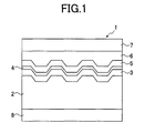
- FIG. 1 is a cross-sectional diagram of one preferred embodiment of the optical storage medium of the invention.
- FIG. 2 is a diagram for explaining a characteristic of storage medium's reflectivity with respect to relative velocity and a characteristic of the differential coefficient of the reflectivity with respect to relative velocity.
- FIG. 3 is a block diagram of one preferred embodiment of the optical recording apparatus of the invention.
- FIG. 4A and FIG. 4B are waveform diagrams for explaining a multi-pulse laser driving waveform used by the optical recording apparatus of FIG. 3.
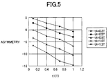
- FIG. 5 is a diagram for explaining the dependence of the write signal asymmetry on the front-end pulse width and the tail-end pulse width of the multi-pulse waveform.
- FIG. 1 is a cross-sectional diagram of one preferred embodiment of the optical storage medium of the invention.
- the optical storage medium of the present embodiment is a rewritable phase-change medium (CD-RW) in which a recording layer of a phase-change material is formed on a substrate.
- CD-RW rewritable phase-change medium
- a substrate 2 As shown in FIG. 1, in the storage medium 1 of this embodiment, a substrate 2, a lower protective layer 3, a recording layer 4, an upper protective layer 5, and a reflection/heat-radiation layer 6 are provided.
- the lower protective layer 3, the recording layer 4, the upper protective layer 5 and the reflection/heat-radiation layer 6 are deposited, in this order, on the front surface of the substrate 2. Further, an over-coat layer 7 may be provided on the reflection/heat-radiation layer 6, and a hard-coat layer 8 may be provided on the back surface of the substrate 2.
- the substrate 2 is provided in order to support the recording layer 4.
- the substrate 2 When a read/write laser beam emitted by a laser light source is incident to the substrate 2 of the storage medium 1, the substrate 2 must be transparent to the incident laser beam having a wavelength of the read/write laser beam used.
- a suitable transparent material of the substrate 2 is selected from among glass materials, ceramics materials and resin materials. Resin materials are more suitable for the substrate 2 because of the transparency and the ease of molding.
- a suitable resin material of the substrate 2 may be selected from one of resin materials including polycarbonate resins, acrylic resins, epoxy resins, polystyrene resins, styrene-acrylonitrile copolymer resins, polyethylene resins, polypropylene resins, silicon-based resins, fluorine-based resins, acrylonitrile-butadiene-styrene (ABS) resins and urethane resins.
- polycarbonate resins or acrylic resins are selected as a more suitable material of the substrate 2, because of the ease of molding, the required optical characteristics and the cost effectiveness.
- a set of guide grooves may be provided on the transparent substrate 2.
- the lower and upper protective layers 3 and 5 are made of a dielectric material because of the required thermal and optical characteristics.
- a suitable material of the protective layers 3 and 5 may be selected from a single-component or mixture dielectric materials including oxides of SiO 2 , SiO, ZnO, SnO 2 , TiO 2 , InO 2 , Mg, ZrO 2 , etc., nitrides of Si 3 N 4 , AlN, TiN, BN, ZrN, etc., sulphides of ZnS, In 2 S 3 , TaS 4 , etc., carbides of SiC, TaC, B4C, WC, TiC, ZrC, etc., and diamond-state carbon.
- the lower and upper protective layers 3 and 5 are deposited by using physical vapor deposition, sputtering, ionplating, or chemical vapor deposition. Because of the productivity and the cost, sputtering is selected as the more suitable one for the formation of the lower and upper protective layers 3 and 5.
- An optimum thickness of the protective layers 3 and 5 may be determined in view of the required thermal and optical characteristics. Typically, the thickness of the protective layers 3 and 5 ranges from 10 nm to 5000 nm.
- the recording layer 4 is made of a phase-change material.
- a suitable phase-change material of the recording layer 4 may be selected from alloy-based phase-change materials including GeTe, GeTeSe, GeTeS, GeSeSb, GeAsSe, InTe, SeTe, SeAs, Ge-Te-(Sn, Au, Pd), GeTeSeSb, GeTeSb, AgInSbTe, etc.
- the composition of elemental substances in each phase-change material may be optimized in accordance with a linear velocity of rotation of the medium.
- a small amount of impurities selected from substances including B, N, C, O, Si, P, S, Ge, Se, Al, Ti, Zr, V, Mn, Fe, Co, Ni, Cr, Cu, Zn, Sn, Pd, Pt, Au, etc., may be mixed with the phase-change material of the recording layer 4.
- the selection of AgInSbTe as the phase-change material of the recording layer 4 is more suitable because it provides definite boundaries between crystalline areas and non-crystalline (or amorphous) areas, which suits to a mark-edge recording technique (which will be described later) that is used by the optical recording method and apparatus of the present invention.
- a small amount of impurities for example, N may be added to the phase-change material, which allows a margin of the linear velocity of the medium rotation to be increased.
- the composition of the phase-change material (AgInSbTe) of the recording layer 4 is represented by the formula Ag ⁇ In ⁇ Sb ⁇ Te ⁇ 0. 1 ⁇ ⁇ ⁇ 3. 0 5. 0 ⁇ ⁇ ⁇ 12. 0 60. 0 ⁇ ⁇ ⁇ 72. 0 22. 0 ⁇ ⁇ ⁇ 30. 0.
- a desired thickness of the phase-change material of the recording layer 4 ranges from 13 nm to 17 nm.
- the recording layer 4 is deposited on the substrate 2 by using physical vapor deposition, sputtering, ionplating, or chemical vapor deposition. Because of the productivity and the cost, sputtering is selected as the more suitable one for the formation of the recording layer 4.
- the reflection/heat radiation layer 6 serves to reflect the read/write light beam and dissipate heat produced during recording.
- a suitable material of the reflection/heat radiation layer 6 may be selected from single-component metals including Ag, Au, Al, or mixture alloys including Ti, Si, Cr, Ta, Cu, Pd, C, etc.
- the reflection/heat radiation layer 6 is made of an aluminum-based alloy because of the required thermal and optical characteristics and the productivity.
- a desired composition of the material of the reflection/heat radiation layer 6 and a desired thickness of the reflection/heat radiation layer 6 may be determined in view of the required thermal and optical characteristics.
- the over-coat layer 7 is made of a resin material containing, as the major component, an optical curing resin or an electron beam curing resin. Because of the ease of curing and the ease of film formation, a resin material containing, as the major component, a UV (ultraviolet ray) curing resin is more suitable for the material of the over-coat layer 7.
- the film formation of the over-coat layer 7 is performed by using a dipping method or a spin-coat method.
- the optical storage medium 1 of the present embodiment be configured to meet the conditions related to the phase-change critical linear velocity (which will be called the velocity "vo").
- a measuring device for measuring the phase-change critical linear velocity (the velocity "vo") of the medium meets the following conditions: the wavelength of a read/write laser beam emitted by the laser light source is 789 nm; and the numerical aperture (NA) of the objective lens is 0.49.
- NA numerical aperture
- the measurement of the velocity "vo” is performed when the medium 1 is moved to the pickup at the relative velocity "v” and the pickup emits a write laser beam to the medium from the laser light source at the measurement power "P E ".
- a pulsed light source emission waveform which is ordinarily used for the recording of conventional phase-change media, is not used for the emission of the laser beam.
- a direct-current (DC) driving waveform is used for the emission of the write laser beam, and a reflectivity of the recorded portion of the medium is detected based on a reflection beam from the medium by a reproducing part of the optical recording apparatus.
- the reflectivity obtained at this time is indicated by a variable R(v) with respect to the relative velocity "v".
- the wavelength of the read laser beam is set at 789 nm.
- FIG. 2 shows a characteristic of the reflectivity "R" of the medium 1 of the present embodiment with respect to the relative velocity "v” and a characteristic of the differential coefficient "- dR/dv” of the reflectivity with respect to relative velocity "v”.
- phase-change critical relative velocity "vo" of the medium is defined by a value of the relative velocity "v” when the differential coefficient "-dR/dv” of the reflectivity is the maximum “(-dR/dv)max” (the peak point).
- a margin " ⁇ vo” of the velocity "vo” is defined by an effective range of the linear velocity "v” when the differential coefficient "-dR/dv” of the reflectivity decays to half the maximum "(-dR/dv)max".
- the phase-change material of the recording layer is selected such that it satisfies the following conditions: vo ⁇ O. 7vwh where "vo" is the phase-change critical linear velocity, and "vwh” is the highest linear velocity.
- the optical storage medium 1 of the present embodiment is configured to meet the above conditions (in other words, the velocity "vo" of the medium 1 is set to satisfy the above conditions), the medium 1 provides good write/erase characteristics as well as improved overwrite performances when the recording is performed at the highest linear velocity "vwh".
- the medium 1 when the medium 1 does not meet the above conditions, it provides poor write/erase characteristics as well as undesired overwrite performances when the recording is performed at the highest linear velocity "vwh".
- the primary reason is that it is difficult that such medium 1 returns the state of a mark on the medium with the reflectivity being at the secondary saturation point R B back to the state of a space on the medium with the reflectivity being at the initial saturation point R A.
- the phase-change material of the recording layer is selected such that it satisfies the following conditions: vo ⁇ 3. Ovwl where "vo” is the phase-change critical linear velocity, and "vwl” is the lowest linear velocity.
- the optical storage medium 1 of the present embodiment is configured to meet the above conditions (in other words, the velocity "vo" of the medium 1 is set to satisfy the above conditions), the medium 1 provides good mark-formation characteristics as well as improved overwrite performances when the recording is performed at the lowest linear velocity "vwl".
- the margin " ⁇ vo” of the medium 1 indicates the tendency of deterioration of the recording signal at the highest linear velocity "vwh".
- the phase-change material of the recording layer is selected such that it satisfies the following conditions: ⁇ vo/vo ⁇ O. 4 where "vo" is the phase-change critical linear velocity, and " ⁇ vo” is the margin of the velocity "vo”.
- the optical storage medium 1 of the present embodiment is configured to meet the above conditions (in other words, the velocity "vo" of the medium 1 is set to satisfy the above conditions), the medium 1 provides improved stability of write/erase characteristics when the recording is performed at the highest linear velocity "vwh".
- the phase-change material of the recording layer is selected such that it satisfies the following conditions: O. 1 ⁇ R A /R B ⁇ 0. 6 where "R A " is the initial saturation point of the medium, and "R B " is the secondary saturation point of the medium.
- the medium 1 provides a good mark/space contrast when the recording is performed.
- the phase-change material of the recording layer is selected such that it satisfies the following conditions: vwh/vwl ⁇ 2. 5 where "vwh” is the highest linear velocity of the medium during the recording, and “vwl” is the lowest linear velocity of the medium during the recording.
- FIG. 3 shows one preferred embodiment of the optical recording apparatus of the invention.
- the optical recording apparatus of the present embodiment is configured to conform to the high-speed specifications of 4X to 10X linear velocity recording for the expected rewritable compact disk standards.
- the optical storage medium 1 is held on and rotated by a spindle motor 11.
- a controller (CTRL)16 controls the spindle motor 11 so that the linear velocity of rotation of the medium 1 is set at a controlled speed.
- a pickup 12 having a laser light source (for example, a laser diode) and optical systems (for example, a focusing lens and an objective lens) is provided to focus a laser beam, emitted by the light source, onto the recording layer of the medium 1 and change the phase of the recording material of the layer.
- the pickup 12 includes a photodetector which detects a reflection laser beam reflected from the recording layer of the medium 1 and outputs a readout signal based on the reflection laser beam.
- a laser diode driver (LDD) 13 is provided to apply a laser driving power to the light source of the pickup 12 to control the emission of a laser beam to the recording layer of the medium 1.
- the LDD 13 applies the driving power to the light source of the pickup 12, and the light source emits the laser beam to the recording layer of the medium 1 to change the phase of the recording material of the layer.
- the photodetector of the pickup 12 detects the reflection laser beam reflected from the recording layer of the medium 1 and outputs the readout signal based on the reflection laser beam.
- the readout signal output by the photodetector of the pickup 12 is used to carry out the reproducing of the recorded information, the tracking servo control and the focusing servo control.
- the readout signal output by the pickup 12 is supplied to a write power monitoring unit (WPMU) 14.
- the write power monitoring unit 14 monitors the readout signal received from the pickup 12.
- a write power calculating unit (WPCU) 15 is provided to calculate the power (or the amplitude) of the readout signal and outputs the calculation result (the calculated power) to the controller 16.
- the controller 16 has a CPU (central processing unit), which controls the elements of the optical recording apparatus of the present embodiment. As described above, the controller 16 controls the rotating speed of the spindle motor 12 so that the linear velocity of rotation of the medium 1 is set at a controlled speed.
- a write power determination unit (WPDU) 17 is provided to set a multi-pulse waveform of the laser driving power that is applied to the pickup 12.
- the controller 16 outputs a control signal to the WPDU 17 based on the feedback result (or the calculated power) from the MPCU 15, so that the WPDU 17 outputs a selected one of a test writing power (TWP) set signal and an optimum writing power (OWP) set signal to the LDD 13.
- TWP test writing power
- OTP optimum writing power
- the pickup 12, the LDD 13, the WPDU 17 and the controller 16 form an optical information recording means 18.
- the optical information recording means 18 carries out a mark-edge recording process for the storage medium 1 wherein a sequence of data blocks (also called the write information), which corresponds to a sequence of mark and space portions of the driving power, are recorded onto the recording layer of the medium 1, each of the mark portions having a pulse width corresponding to a multiple of a period (T) of a write clock based on a PWM (pulse width modulation) method.
- a sequence of data blocks also called the write information
- the optical information recording means 18 converts each data block in the write information into a power level and a pulse width in the driving waveform by using an EFM (eight to fourteen modulation) process or another improved modulation technique based on the period T of the write clock.
- the WPDU 17 sets a multi-pulse laser waveform of the driving power in order to control the emission of a laser beam by the laser light source of the pickup 12 to the recording layer of the medium 1 (CD-RW).
- FIG. 4A and FIG. 4B are waveform diagrams for explaining the multi-pulse laser driving waveform used by the optical recording apparatus of FIG. 3.
- FIG. 4A shows the waveform of a 5T input signal where "T” indicates the period of the write clock in the optical recording apparatus of FIG. 3.
- the "5T” input signal means that this pulsed signal has a pulse width that is 5 times the period T of the write clock.
- the high-level signal portion represents "1" of the write information and corresponds a mark on the recording layer of the medium 1
- the low-level signal portions represent "0" of the write information and correspond to spaces on the recording layer of the medium 1.
- FIG. 4B shows an example of the multi-pulse laser driving waveform that is set by the WPDU 17 of the present embodiment in response to the input signal of FIG. 4A.
- the multi-pulse waveform supplied from the WPDU 17 to the LDD 13, includes a front-end portion "fp", a multi-pulse portion “mp” and a tail-end portion "op".
- the front-end portion “fp” has a first pulse width "t1" with a high-power write level “Pw” and starts from a middle-power erase level “Pe”.
- the multi-pulse portion “mp” includes a sequence of write pulses each having a second pulse width "t2" with the write level Pw and a third pulse width "t3" with a low-power base level "Pb".
- Pb ⁇ Pe ⁇ Pw are met.
- the tail-end portion "op” has a fourth pulse width "t4" with the base level Pb and ends at the erase level Pe.
- a non-crystalline area (the amorphous phase) that represents "1" of the write information is formed as a mark on the recording layer of the medium 1 by the emission of a laser beam from the light source to the medium 1.
- the formation of the amorphous phase of the recording material on the recording layer of the medium 1 requires heating of the recording layer to an increased temperature above the melting point of the recording material and cooling of the recording layer for an adequate time after the heating.
- the front-end portion "fp” which has the first pulse width t1 with the high-power write level Pw, provides the recording layer of the medium 1 with the energy needed to heat it to the increased temperature above the melting point.
- the tail-end portion "op" which has the fourth pulse width t4 with the low-power base level Pb, serves to cool the recording layer of the medium 1 for an adequate time after the heating.
- the fourth pulse width t4 is set at an optimum value and the waveform of the present embodiment is applied, a tail-end edge of the mark can be accurately and definitely formed on the recording layer of the medium 1.
- the optical recording apparatus of the present embodiment is configured such that the controller 16 causes the write power determination unit (WPDU) 17 to control the multi-pulse waveform of FIG.
- FIG. 5 shows the dependence of the write signal asymmetry on the front-end pulse width "t1" and the tail-end pulse width "t4" of the multi-pulse waveform.
- the controller 16 causes the WPDU 17 to control the waveform when the linear velocity of rotation of the medium 1 is set in a high-speed range from 5 m/s to 28 m/s, such that the first pulse width t1 of the front-end portion ranges 0.1T to 1T and the fourth pulse width t4 of the tail-end portion ranges 0.2T to 1.3T.
- the experiments are performed under the following conditions.
- a CD-RW disk that is provided in conformity with the above-described embodiment of the optical storage medium of the invention is used for the experiments, and the CD-RW disk is called the medium 1.
- the wavelength of a laser beam emitted by the laser light source of the pickup 12 in the optical recording apparatus is 780 nm.
- the numerical aperture (NA) of the objective lens of the pickup 12 is set at 0.5.
- a high-speed recording of the medium 1 is performed at 9.6 m/s linear speed (which is equivalent to 8X linear velocity of the rewritable compact disk standards).
- the first pulse width "t1" of the front-end portion "fp” of the multi-pulse waveform is sequentially changed to one among 0.1T, 0.4T, 0.7T and 1.0T, and, at the same time, the fourth pulse width "t4" of the tail-end portion "op” of the multi-pulse waveform is changed to one among 0.2T, 0.5T, 0.8T, 1.0T and 1.3T with respect to each of the respective first pulse width values.
- the dependence of the write signal asymmetry on the front-end pulse width "t1" and the tail-end pulse width "t4" of the multi-pulse waveform is evaluated.
- FIG. 5 shows such results of the evaluations.
- the write signal asymmetry indicates the degree of asymmetry of mark length and space length, and it is represented by a normalized value obtained by dividing a difference between the average level of the radio-frequency (RF) signal amplitude of the longest mark and the average level of the RF signal amplitude of the shortest mark by the RF signal amplitude of the longest mark.
- RF radio-frequency
- the specifications of the rewritable compact disk standards provide the requirements: -15 ⁇ asymmetry ⁇ 5.
- the front-end pulse width "t1" of the multi-pulse waveform ranges from 0.1T to 1.0T and the tail-end pulse width "t4" of the multi-pulse waveform ranges from 0.2T to 1.3T.
- the optical storage medium 1 is prepared, in advance, to contain a sequence of data blocks recorded on the recording layer, each data block including first information indicative of the first pulse width t1 of the front-end portion "fp" and second information indicative of the fourth pulse width t4 of the tail-end portion "op" in the multi-pulse waveform.
- optimum values of the first pulse width t1 and the fourth pulse width t4 that are suited to a specific phase-change material of each individual medium 1 are predetermined.
- wobbling grooves or the like, carrying both the first information and the second information are formed on the medium 1.
- a test writing process is performed in which test data blocks are recorded onto a test-write region (for example, a power calibration area PCA) of the medium 1 and a readout signal is detected from the test-write region of the medium 1, the readout signal indicative of the first information and the second information related to the test data blocks. Further, optimum values of the first pulse width t1 and the fourth pulse width t4 are calculated based on the first information and the second information indicated by the readout signal. In the present embodiment, the multi-pulse waveform is controlled based on the optimum values of the first pulse width tl and the fourth pulse width t4.
- the optimum values of the first pulse width t1 and the fourth pulse width t4 in the multi-pulse waveform can be suitably determined.
- the optical recording method and apparatus of the present embodiment are effective in preventing the occurrence of a read error after the recording of the medium 1 is performed, due to deterioration of the write signal quality of the medium 1.
- the optical storage medium 1 that is formatted, in advance, to contain the first information indicative of the first pulse width t1 of the front-end portion "fp" and the second information indicative of the fourth pulse width t4 of the tail-end portion "op" in the multi-pulse waveform.
- the formatted medium 1 of the present embodiment provides the users with the ease-to-use feature as well as good write/erase characteristics of the rewritable phase-change medium when the high-speed recording is performed.
Landscapes
- Physics & Mathematics (AREA)
- Optics & Photonics (AREA)
- Optical Recording Or Reproduction (AREA)
- Optical Head (AREA)
- Optical Record Carriers And Manufacture Thereof (AREA)
Applications Claiming Priority (2)
| Application Number | Priority Date | Filing Date | Title |
|---|---|---|---|
| JP2000058399A JP3839635B2 (ja) | 2000-03-03 | 2000-03-03 | 光情報記録方法、光情報記録装置及び光情報記録媒体 |
| JP2000058399 | 2000-03-03 |
Publications (1)
| Publication Number | Publication Date |
|---|---|
| EP1130583A1 true EP1130583A1 (de) | 2001-09-05 |
Family
ID=18578997
Family Applications (1)
| Application Number | Title | Priority Date | Filing Date |
|---|---|---|---|
| EP01104495A Ceased EP1130583A1 (de) | 2000-03-03 | 2001-03-01 | Verfahren und Vorrichtung zur optischen Aufzeichnung, und optisches Speichermedium |
Country Status (3)
| Country | Link |
|---|---|
| US (5) | US6631109B2 (de) |
| EP (1) | EP1130583A1 (de) |
| JP (1) | JP3839635B2 (de) |
Cited By (8)
| Publication number | Priority date | Publication date | Assignee | Title |
|---|---|---|---|---|
| EP1248253A3 (de) * | 2001-04-06 | 2004-10-13 | Ricoh Company, Ltd. | Optisches Informationsaufzeichnungsmedium, Informationsaufzeichnungsverfahren, und dieses Aufzeichnungsmedium benutzendes Gerät |
| EP1229530A3 (de) * | 2001-02-01 | 2006-10-18 | Ricoh Company, Ltd. | Optisches Informationsaufzeichnungsmedium |
| EP1418574A3 (de) * | 2002-11-06 | 2006-12-13 | Ricoh Company, Ltd. | Informationsaufzeichnungsgerät und Informationsaufzeichnungsverfahren |
| SG129233A1 (en) * | 2001-09-29 | 2007-02-26 | Samsung Electronics Co Ltd | Method and apparatus for recording data on opticalrecording medium |
| US7274647B2 (en) | 2001-09-29 | 2007-09-25 | Samsung Electronics Co., Ltd. | Method of and apparatus for recording data on optical recording medium |
| EP1684269A4 (de) * | 2003-11-14 | 2009-02-04 | Ricoh Kk | Informationsaufzeichnungsverfahren, informationsaufzeichnungseinrichtung und informationsmedium, das ein programm enthält |
| EP2690461A1 (de) | 2012-07-26 | 2014-01-29 | Sercel | Verfahren zur Schätzung der Wassergeschwindigkeit eines akustischen Knotens |
| EP2690467A1 (de) | 2012-07-25 | 2014-01-29 | Sercel | Verfahren zum Steuern einer akustischen linearen Schleppantenne |
Families Citing this family (18)
| Publication number | Priority date | Publication date | Assignee | Title |
|---|---|---|---|---|
| JP3839635B2 (ja) * | 2000-03-03 | 2006-11-01 | 株式会社リコー | 光情報記録方法、光情報記録装置及び光情報記録媒体 |
| JP4142338B2 (ja) * | 2002-05-09 | 2008-09-03 | 富士フイルム株式会社 | 光情報記録方法 |
| JP3954438B2 (ja) * | 2002-05-31 | 2007-08-08 | Tdk株式会社 | 光記録媒体への情報記録方法、情報記録装置及び光記録媒体 |
| US7260044B2 (en) * | 2002-09-06 | 2007-08-21 | Ricoh Company, Ltd. | Recording method for a phase-change optical recording medium |
| EP1783754B1 (de) * | 2002-10-10 | 2008-10-01 | Matsushita Electric Industrial Co., Ltd. | Optisches Datenaufzeichnungsmedium |
| US7116623B2 (en) * | 2002-10-28 | 2006-10-03 | Matsushita Electric Industrial Co., Ltd. | Optical information recording method, optical information recording device and optical information recording medium |
| JP2004171642A (ja) * | 2002-11-19 | 2004-06-17 | Tdk Corp | 光記録媒体、光記録方法及び光記録装置 |
| US7310293B2 (en) * | 2003-04-04 | 2007-12-18 | Matsushita Electric Industrial Co., Ltd. | Method and apparatus for controlling laser power using a test light emission pattern having a multipulse light emission interval |
| JP2005044491A (ja) * | 2003-07-10 | 2005-02-17 | Ricoh Co Ltd | 光記録媒体およびその製造方法 |
| EP1515315B1 (de) * | 2003-08-26 | 2007-07-25 | Ricoh Company, Ltd. | Informationsaufzeichnungsverfahren, Informationsaufzeichnungsvorrichtung, optisches Informationsaufzeichnungsmedium, Programm zur Aufzeichnung von Informationen und Speichermedium |
| JP3732499B2 (ja) * | 2003-08-26 | 2006-01-05 | 株式会社リコー | 色素系追記型dvd媒体の記録再生方法及び装置 |
| KR101094178B1 (ko) * | 2003-11-12 | 2011-12-14 | 주식회사 히타치엘지 데이터 스토리지 코리아 | 프론트 포토 디텍터의 유입 반사광 검출 및 광디스크장치의 이상유무 검출방법 |
| TW200525531A (en) * | 2004-01-30 | 2005-08-01 | Victor Company Of Japan | Optical recording method, optical recording apparatus and optical storage medium |
| JP4446348B2 (ja) * | 2004-03-18 | 2010-04-07 | 株式会社リコー | 情報記録方法及び情報記録装置 |
| JP2005267801A (ja) * | 2004-03-19 | 2005-09-29 | Sony Corp | ディスクドライブ装置 |
| KR20060027906A (ko) * | 2004-09-24 | 2006-03-29 | 삼성전자주식회사 | 광 기록재생장치 및 그의 기록방식 결정방법 |
| US20060174256A1 (en) * | 2005-02-03 | 2006-08-03 | Tohru Yashiro | Optical recording medium, production method thereof, and, method and apparatus for recording and reproducing optical recording medium |
| US20060188684A1 (en) * | 2005-02-22 | 2006-08-24 | Katsuyuki Yamada | Optical recording medium, optical recording method and apparatus |
Citations (7)
| Publication number | Priority date | Publication date | Assignee | Title |
|---|---|---|---|---|
| JPS6329336A (ja) | 1986-07-22 | 1988-02-08 | Hitachi Maxell Ltd | 光デイスク |
| EP0442566A1 (de) * | 1990-02-12 | 1991-08-21 | Koninklijke Philips Electronics N.V. | Informationsaufzeichnungsanordnung |
| EP0737962A2 (de) * | 1995-04-14 | 1996-10-16 | Ricoh Company, Ltd | Datenaufzeichnungs-/-wiedergabeverfahren, Datenaufzeichnungs-/-wiedergabegerät und Datenaufzeichnungsmedium |
| EP0802531A2 (de) | 1996-04-17 | 1997-10-22 | Hitachi, Ltd. | Verfahren und Vorrichtung zur Informationsaufzeichnung |
| WO1998036411A2 (en) * | 1997-02-14 | 1998-08-20 | Koninklijke Philips Electronics N.V. | Method and device for writing an optical record carrier |
| EP0898272A2 (de) * | 1997-08-15 | 1999-02-24 | Ricoh Company, Ltd. | Optisches Aufzeichnungsmedium sowie dieses Medium einsetzende Aufzeichnungs- und Wiedergabeverfahren |
| EP0986054A1 (de) * | 1998-09-14 | 2000-03-15 | Matsushita Electric Industrial Co., Ltd. | Optisches Datenaufzeichnungsverfahren und Datenaufzeichnungsmedium |
Family Cites Families (19)
| Publication number | Priority date | Publication date | Assignee | Title |
|---|---|---|---|---|
| JPS63266633A (ja) | 1987-04-23 | 1988-11-02 | Fuji Photo Film Co Ltd | 光情報記録方法 |
| JP2702923B2 (ja) | 1987-04-24 | 1998-01-26 | 株式会社日立製作所 | 情報の記録方法及び情報記録装置 |
| JP2707289B2 (ja) | 1988-09-27 | 1998-01-28 | キヤノン株式会社 | 情報記録再生装置 |
| JP3287648B2 (ja) * | 1993-06-07 | 2002-06-04 | 株式会社リコー | 相変化型情報記録媒体の記録同時ベリファイ方法及び相変化型情報記録ドライブ装置 |
| JP3022770B2 (ja) | 1996-04-16 | 2000-03-21 | 三菱化学株式会社 | 光記録方法、装置及び光記録媒体 |
| JPH1083553A (ja) | 1996-09-05 | 1998-03-31 | Hitachi Ltd | 情報記録方法及び情報記録装置 |
| JP3782223B2 (ja) | 1997-08-15 | 2006-06-07 | 株式会社リコー | 光記録媒体及びこれの記録再生方法 |
| JPH1170738A (ja) | 1997-08-28 | 1999-03-16 | Ricoh Co Ltd | 光記録媒体 |
| JPH11259912A (ja) * | 1997-12-25 | 1999-09-24 | Tdk Corp | 光記録媒体 |
| JP2000137928A (ja) | 1998-10-30 | 2000-05-16 | Ricoh Co Ltd | 光記録媒体および光記録方法 |
| JP2000229479A (ja) * | 1998-12-09 | 2000-08-22 | Tdk Corp | 光記録媒体 |
| JP2000348397A (ja) * | 1999-03-29 | 2000-12-15 | Tdk Corp | 情報媒体、情報再生方法および情報再生装置 |
| JP2000322739A (ja) | 1999-05-10 | 2000-11-24 | Tdk Corp | 光記録方法 |
| US6459666B1 (en) * | 1999-09-06 | 2002-10-01 | Ricoh Company, Ltd. | Information recording apparatus and method |
| EP1117094B1 (de) * | 2000-01-17 | 2012-11-21 | Mitsubishi Kagaku Media Co., Ltd. | Aufzeichnungsverfahren für ein Phasenänderungsaufzeichnungsmedium |
| JP3839635B2 (ja) * | 2000-03-03 | 2006-11-01 | 株式会社リコー | 光情報記録方法、光情報記録装置及び光情報記録媒体 |
| JP2001319370A (ja) * | 2000-05-11 | 2001-11-16 | Nec Corp | 相変化光ディスク |
| US6700862B2 (en) * | 2000-10-03 | 2004-03-02 | Matsushita Electric Industrial Co., Ltd. | Optical disc and manufacturing method for the same |
| JP4386594B2 (ja) * | 2001-03-08 | 2009-12-16 | パイオニア株式会社 | 多層情報記録媒体 |
-
2000
- 2000-03-03 JP JP2000058399A patent/JP3839635B2/ja not_active Expired - Lifetime
-
2001
- 2001-03-01 US US09/795,436 patent/US6631109B2/en not_active Expired - Lifetime
- 2001-03-01 EP EP01104495A patent/EP1130583A1/de not_active Ceased
-
2003
- 2003-08-12 US US10/638,500 patent/US7193950B2/en not_active Expired - Lifetime
-
2004
- 2004-12-01 US US11/000,202 patent/US7206271B2/en not_active Expired - Lifetime
-
2006
- 2006-07-24 US US11/491,241 patent/US7799181B2/en not_active Expired - Fee Related
- 2006-07-24 US US11/491,240 patent/US7382706B2/en not_active Expired - Lifetime
Patent Citations (7)
| Publication number | Priority date | Publication date | Assignee | Title |
|---|---|---|---|---|
| JPS6329336A (ja) | 1986-07-22 | 1988-02-08 | Hitachi Maxell Ltd | 光デイスク |
| EP0442566A1 (de) * | 1990-02-12 | 1991-08-21 | Koninklijke Philips Electronics N.V. | Informationsaufzeichnungsanordnung |
| EP0737962A2 (de) * | 1995-04-14 | 1996-10-16 | Ricoh Company, Ltd | Datenaufzeichnungs-/-wiedergabeverfahren, Datenaufzeichnungs-/-wiedergabegerät und Datenaufzeichnungsmedium |
| EP0802531A2 (de) | 1996-04-17 | 1997-10-22 | Hitachi, Ltd. | Verfahren und Vorrichtung zur Informationsaufzeichnung |
| WO1998036411A2 (en) * | 1997-02-14 | 1998-08-20 | Koninklijke Philips Electronics N.V. | Method and device for writing an optical record carrier |
| EP0898272A2 (de) * | 1997-08-15 | 1999-02-24 | Ricoh Company, Ltd. | Optisches Aufzeichnungsmedium sowie dieses Medium einsetzende Aufzeichnungs- und Wiedergabeverfahren |
| EP0986054A1 (de) * | 1998-09-14 | 2000-03-15 | Matsushita Electric Industrial Co., Ltd. | Optisches Datenaufzeichnungsverfahren und Datenaufzeichnungsmedium |
Cited By (23)
| Publication number | Priority date | Publication date | Assignee | Title |
|---|---|---|---|---|
| EP1229530A3 (de) * | 2001-02-01 | 2006-10-18 | Ricoh Company, Ltd. | Optisches Informationsaufzeichnungsmedium |
| US7482109B2 (en) | 2001-02-01 | 2009-01-27 | Ricoh Company, Ltd. | Optical information recording medium |
| EP1248253A3 (de) * | 2001-04-06 | 2004-10-13 | Ricoh Company, Ltd. | Optisches Informationsaufzeichnungsmedium, Informationsaufzeichnungsverfahren, und dieses Aufzeichnungsmedium benutzendes Gerät |
| US6914866B2 (en) | 2001-04-06 | 2005-07-05 | Ricoh Company, Ltd. | Optical information recording medium and information recording method and apparatus using the recording medium |
| US7313078B2 (en) | 2001-09-29 | 2007-12-25 | Samsung Electronics Co., Ltd. | Method of and apparatus for recording data on optical recording medium |
| SG161739A1 (en) * | 2001-09-29 | 2010-06-29 | Samsung Electronics Co Ltd | Method of recording data on an optical recording medium |
| US7274647B2 (en) | 2001-09-29 | 2007-09-25 | Samsung Electronics Co., Ltd. | Method of and apparatus for recording data on optical recording medium |
| US7280460B2 (en) | 2001-09-29 | 2007-10-09 | Samsung Electronics Co., Ltd. | Method of and apparatus for recording data on optical recording medium |
| US7295505B2 (en) | 2001-09-29 | 2007-11-13 | Samsung Electronics Co., Ltd. | Method of and apparatus for recording data on optical recording medium |
| US7301884B2 (en) | 2001-09-29 | 2007-11-27 | Samsung Electronics Co., Ltd. | Method of and apparatus for recording data on optical recording medium |
| SG129233A1 (en) * | 2001-09-29 | 2007-02-26 | Samsung Electronics Co Ltd | Method and apparatus for recording data on opticalrecording medium |
| US7336588B2 (en) | 2001-09-29 | 2008-02-26 | Samsung Electronics Co., Ltd. | Method of and apparatus for recording data on optical recording medium |
| US7388824B2 (en) | 2001-09-29 | 2008-06-17 | Samsung Electronics Co., Ltd. | Method of and apparatus for recording data on optical recording medium |
| US8416665B2 (en) | 2001-09-29 | 2013-04-09 | Samsung Electronics Co., Ltd. | Method of and apparatus for recording data on optical recording medium |
| SG163429A1 (en) * | 2001-09-29 | 2010-08-30 | Samsung Electronics Co Ltd | Optical recording medium and apparatus for forming a recording pattern and an erase pattern thereon |
| SG162610A1 (en) * | 2001-09-29 | 2010-07-29 | Samsung Electronics Co Ltd | Apparatus for forming a first state and a second state on an optical recording medium |
| US7525890B2 (en) | 2001-09-29 | 2009-04-28 | Samsung Electronics Co., Ltd. | Method of and apparatus for recording data on optical recording medium |
| SG132564A1 (en) * | 2001-09-29 | 2007-06-28 | Samsung Electronics Co Ltd | Method of forming a first state and a second state on an optical recording medium |
| EP1418574A3 (de) * | 2002-11-06 | 2006-12-13 | Ricoh Company, Ltd. | Informationsaufzeichnungsgerät und Informationsaufzeichnungsverfahren |
| US7512050B2 (en) | 2003-11-14 | 2009-03-31 | Ricoh Company, Ltd. | Information recording method, information recording device, and recording medium containing a program, with recording marks formed by emitting light |
| EP1684269A4 (de) * | 2003-11-14 | 2009-02-04 | Ricoh Kk | Informationsaufzeichnungsverfahren, informationsaufzeichnungseinrichtung und informationsmedium, das ein programm enthält |
| EP2690467A1 (de) | 2012-07-25 | 2014-01-29 | Sercel | Verfahren zum Steuern einer akustischen linearen Schleppantenne |
| EP2690461A1 (de) | 2012-07-26 | 2014-01-29 | Sercel | Verfahren zur Schätzung der Wassergeschwindigkeit eines akustischen Knotens |
Also Published As
| Publication number | Publication date |
|---|---|
| US20050094545A1 (en) | 2005-05-05 |
| US7799181B2 (en) | 2010-09-21 |
| US20040047265A1 (en) | 2004-03-11 |
| US20070048665A1 (en) | 2007-03-01 |
| US7382706B2 (en) | 2008-06-03 |
| US7206271B2 (en) | 2007-04-17 |
| US20070065755A1 (en) | 2007-03-22 |
| JP3839635B2 (ja) | 2006-11-01 |
| US6631109B2 (en) | 2003-10-07 |
| JP2001250230A (ja) | 2001-09-14 |
| US20010019523A1 (en) | 2001-09-06 |
| US7193950B2 (en) | 2007-03-20 |
Similar Documents
| Publication | Publication Date | Title |
|---|---|---|
| US6631109B2 (en) | Optical recording method and apparatus, and optical storage medium | |
| JP3839213B2 (ja) | 相変化型光記録媒体の記録方法および記録再生装置 | |
| EP1172810B1 (de) | Optisches Aufzeichnungsmedium | |
| US7417930B2 (en) | Optical recording method | |
| US7336580B2 (en) | Optical recording method, optical recorder, and optical recording medium | |
| EP1763021A2 (de) | Optisches Phasenwechselaufzeichnungsmedium | |
| JPH11115313A (ja) | 光記録媒体及びこれの記録再生方法 | |
| JP2001126315A (ja) | 光学的情報記録媒体 | |
| JP4145018B2 (ja) | 光情報記録媒体 | |
| EP1489602A1 (de) | Aufzeichnungsvorrichtung und aufzeichnungsverfahren | |
| JP4001272B2 (ja) | 情報記録方法及び装置 | |
| JP4410081B2 (ja) | 光記録方法 | |
| JP3871593B2 (ja) | 相変化型光情報記録媒体の記録方法及び記録装置 | |
| JP2004095087A (ja) | 光記録媒体、その記録方法および記録装置 | |
| JP2002260226A (ja) | 光情報記録媒体、光情報記録方法及び光情報記録装置 | |
| JP2002092889A (ja) | 相変化記録光ディスクのダイレクトオーバーライト方法及び情報記録再生装置 | |
| JP2004110884A (ja) | 光記録装置および光記録方法 | |
| JP2003168215A (ja) | 光情報記録媒体への記録方法および記録装置 | |
| JP2003059046A (ja) | 記録方法および記録装置 | |
| JP2003136840A (ja) | 光情報記録媒体 | |
| JP2003272147A (ja) | 記録装置及び記録方法 | |
| JP2002230827A (ja) | 相変化型光情報記録媒体 | |
| JP2001121819A (ja) | 光学的情報記録媒体 |
Legal Events
| Date | Code | Title | Description |
|---|---|---|---|
| PUAI | Public reference made under article 153(3) epc to a published international application that has entered the european phase |
Free format text: ORIGINAL CODE: 0009012 |
|
| AK | Designated contracting states |
Kind code of ref document: A1 Designated state(s): AT BE CH CY DE DK ES FI FR GB GR IE IT LI LU MC NL PT SE TR |
|
| AX | Request for extension of the european patent |
Free format text: AL;LT;LV;MK;RO;SI |
|
| 17P | Request for examination filed |
Effective date: 20020206 |
|
| AKX | Designation fees paid |
Free format text: DE ES FR GB IT NL |
|
| 17Q | First examination report despatched |
Effective date: 20071121 |
|
| STAA | Information on the status of an ep patent application or granted ep patent |
Free format text: STATUS: THE APPLICATION HAS BEEN REFUSED |
|
| 18R | Application refused |
Effective date: 20100702 |