EP1130677A2 - Streifenleiterantenne mit begrenzter Grundfäche - Google Patents
Streifenleiterantenne mit begrenzter Grundfäche Download PDFInfo
- Publication number
- EP1130677A2 EP1130677A2 EP01301456A EP01301456A EP1130677A2 EP 1130677 A2 EP1130677 A2 EP 1130677A2 EP 01301456 A EP01301456 A EP 01301456A EP 01301456 A EP01301456 A EP 01301456A EP 1130677 A2 EP1130677 A2 EP 1130677A2
- Authority
- EP
- European Patent Office
- Prior art keywords
- ground plane
- feed line
- antenna
- signal feed
- patch element
- Prior art date
- Legal status (The legal status is an assumption and is not a legal conclusion. Google has not performed a legal analysis and makes no representation as to the accuracy of the status listed.)
- Withdrawn
Links
Images



Classifications
-
- H—ELECTRICITY
- H01—ELECTRIC ELEMENTS
- H01Q—ANTENNAS, i.e. RADIO AERIALS
- H01Q13/00—Waveguide horns or mouths; Slot antennas; Leaky-waveguide antennas; Equivalent structures causing radiation along the transmission path of a guided wave
- H01Q13/08—Radiating ends of two-conductor microwave transmission lines, e.g. of coaxial lines, of microstrip lines
-
- H—ELECTRICITY
- H01—ELECTRIC ELEMENTS
- H01Q—ANTENNAS, i.e. RADIO AERIALS
- H01Q9/00—Electrically-short antennas having dimensions not more than twice the operating wavelength and consisting of conductive active radiating elements
- H01Q9/04—Resonant antennas
- H01Q9/0407—Substantially flat resonant element parallel to ground plane, e.g. patch antenna
-
- H—ELECTRICITY
- H01—ELECTRIC ELEMENTS
- H01Q—ANTENNAS, i.e. RADIO AERIALS
- H01Q19/00—Combinations of primary active antenna elements and units with secondary devices, e.g. with quasi-optical devices, for giving the antenna a desired directional characteristic
- H01Q19/10—Combinations of primary active antenna elements and units with secondary devices, e.g. with quasi-optical devices, for giving the antenna a desired directional characteristic using reflecting surfaces
-
- H—ELECTRICITY
- H01—ELECTRIC ELEMENTS
- H01Q—ANTENNAS, i.e. RADIO AERIALS
- H01Q3/00—Arrangements for changing or varying the orientation or the shape of the directional pattern of the waves radiated from an antenna or antenna system
- H01Q3/12—Arrangements for changing or varying the orientation or the shape of the directional pattern of the waves radiated from an antenna or antenna system using mechanical relative movement between primary active elements and secondary devices of antennas or antenna systems
- H01Q3/16—Arrangements for changing or varying the orientation or the shape of the directional pattern of the waves radiated from an antenna or antenna system using mechanical relative movement between primary active elements and secondary devices of antennas or antenna systems for varying relative position of primary active element and a reflecting device
- H01Q3/20—Arrangements for changing or varying the orientation or the shape of the directional pattern of the waves radiated from an antenna or antenna system using mechanical relative movement between primary active elements and secondary devices of antennas or antenna systems for varying relative position of primary active element and a reflecting device wherein the primary active element is fixed and the reflecting device is movable
-
- H—ELECTRICITY
- H01—ELECTRIC ELEMENTS
- H01Q—ANTENNAS, i.e. RADIO AERIALS
- H01Q9/00—Electrically-short antennas having dimensions not more than twice the operating wavelength and consisting of conductive active radiating elements
- H01Q9/04—Resonant antennas
- H01Q9/0407—Substantially flat resonant element parallel to ground plane, e.g. patch antenna
- H01Q9/045—Substantially flat resonant element parallel to ground plane, e.g. patch antenna with particular feeding means
- H01Q9/0457—Substantially flat resonant element parallel to ground plane, e.g. patch antenna with particular feeding means electromagnetically coupled to the feed line
Definitions
- the present invention relates generally to improvements to antennas, and more particularly to advantageous aspects of a patch antenna with a finite ground plane.
- microstrip patch antenna In a microstrip patch antenna, the radiator is typically provided by a metallic patch element that has been fabricated, using microstrip techniques, onto a dielectric substrate above a ground plane. Because of their low profile, low cost, and compact size, microstrip patch antennas are suitable for various microwave antenna and antenna array applications. Microstrip patch antennas are used, for example, as the radiating elements of designs based on a microwave integrated circuit (MIC) or monolithic microwave integrated circuit (MMIC) such as those used in aircraft and satellite communications, in missile and rocket antenna systems, as well as personal communication system (PCS) wireless applications.
- MIC microwave integrated circuit
- MMIC monolithic microwave integrated circuit
- PCS personal communication system
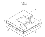
- Fig. 1 shows a cutaway perspective view of a microstrip patch antenna 10 according to the prior art.
- the antenna 10 comprises a square patch element 12, a ground plane 14, and a microstrip feed line 16, lying on parallel planes defined by the top and bottom surfaces of a pair of dielectric substrates 18 and 20.
- the patch element 12 is fabricated onto the top surface of the upper substrate 18, the ground plane 14 is fabricated between the bottom surface of the upper substrate 18 and the top surface of the lower substrate 20, and the feed line 16 is fabricated onto the bottom surface of the lower substrate 20.
- a fixed metal plate reflector 22 is provided at the bottom of the antenna 10 to reflect radiation towards the top of the antenna 10.
- Coupling between the feed line 16 and the patch element 12 is provided by a small rectangular aperture 24 in the ground plane 14 that lies across the feed line 16. Because of this coupling technique, the design shown in Fig. 1 is known as an "aperture-coupled patch antenna.” Other designs are also used, employing different techniques to couple the feed line to the patch element.
- the ground plane 14 is significantly larger than the aperture 24 such that, from an electromagnetic perspective, the ground plane 14 functions as an infinite surface relative to the aperture 24. This helps the isolation between the feed line 16 and the patch element 12. In addition, the use of an infinite ground plane makes analysis of the antenna much easier because the equivalence theorem can be applied.
- An antenna's radiation pattern is important in antenna applications. It includes several parameters to characterize the antenna performance, including gain, 3 dB (half-power) beamwidth, side-lobe level, front-to-back (F/B) ratio, polarization, cross-polarization level, and the line.
- the 3 dB beamwidth parameter is the main parameter to show the coverage of radiated energy.
- the beamwidth of a conventional patch antenna is approximately 60° to 70°.
- TDMA time division multiple access
- CDMA code division multiple access
- a dipole element with an angular reflector can be employed to provide beamwidth control by mechanically adjusting the reflector angle.
- this approach requires sophisticated mechanical structures which may not be cost effective, and which may also result in an undesirably large package size to accommodate these structures.
- the antenna comprises a patch element and a ground plane separated from the patch element by a first dielectric layer.
- the antenna further includes a signal feed line separated from the ground plane by a second dielectric layer, the signal feed line being shielded from the patch element by the ground plane.
- the signal feed line is electromagnetically coupled to the patch element through an aperture in the ground plane lying across the signal feed line, the ground plane functioning as a finite surface relative to the aperture.
- the beamwidth of the antenna is adjusted by adjusting the position of a reflector behind the signal feed line.
- Fig. 1 shows a partial cutaway perspective view of a microstrip patch antenna according to the prior art.
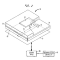
- Fig. 2 shows a partial cutaway perspective view of a first embodiment of a microstrip patch antenna according to the present invention.
- Figs. 3A through 3D show, respectively, top, side, front, and bottom views of a further embodiment of a microstrip patch antenna according to the present invention.
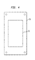
- Fig. 4 shows a bottom view of the top substrate layer of the antenna shown in Figs. 3A through 3D.
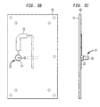
- Figs. 5A through 5C show, respectively, top, bottom, and side views of the bottom substrate layer of the antenna shown in Figs. 3A through 3D.
- the antenna has a patch element, a ground plane separated from the patch element by a first dielectric layer, and a signal feed line separated from the ground plane by a second dielectric layer.
- the signal feed line is shielded from the patch element by the ground plane, and the signal feed line is electromagnetically coupled to the patch element through an aperture in the ground plane lying across the signal feed line.
- the ground plane functions as a finite surface relative to the aperture.
- Fig. 2 shows a partial cutaway perspective view of a first embodiment of a patch antenna 30 according to the present invention.
- the Fig. 2 patch antenna 30 includes a patch element 32, a finite ground plane 34, and a microstrip feed line 36 lying on parallel planes defined by upper and lower substrates 38 and 40.
- a reflector 42 is provided to reflect radiation towards the top of the antenna 30.
- the patch element 32 is coupled to the microstrip feed line 36 by a rectangular aperture 44 in the finite ground plane 34.
- the dimensions of the finite ground plane 34 are chosen such that it behaves as a finite surface relative to the aperture 44.
- the upper limit of the ground plane width is dictated by the edge diffraction conditions which, in the present embodiment of the invention, are derived from the distance of the edges of the ground plane 34 to the radiation caustic, namely, the patch element 32. Therefore, in the present embodiment of the invention, the definition of the "finite" ground plane 34 is that the width of the ground plane 34 is less than one-half wavelength of the operation frequency (0.5 ⁇ ) to allow measurable beamwidth variation due to variant reflector positions. Also, the width of the ground plane 34 is more than 1.5 times the width of the patch element 32 to allow a good voltage standing wave ratio (VSWR) performance.
- VSWR voltage standing wave ratio
- the finite ground plane 34 significantly enhances the beamwidth of the antenna 30.
- the beamwidth of the antenna can be increased to 85°.
- the beamwidth capabilities of the antenna 30 are further improved by modifying the shape of the patch element 32.
- the patch element is typically square.
- the use of the rectangular patch element 32 in combination with the finite ground plane 34 has been shown to increase the beamwidth of the antenna 30 to 90°
- the Fig. 2 antenna 30 provides a system for adjusting the antenna beamwidth.
- a finite ground plane 34 it has been found that it is possible to adjust the beamwidth of the antenna 30 by adjusting the position of the reflector 42 relative to the microstrip feed line 36. Moving the reflector 42 away the feed line 36 increases the "spill" of radiation around the reflector, thereby resulting in an increase in beamwidth.
- the beamwidth can be adjusted to any value in the range of 80° to 110°, without de-tuning the antenna's impedance matching.
- adjustment of the reflector is accomplished by mounting the reflector 42 to a digital stepper motor 46 that is operated by a microprocessor controller 48. It will be recognized that other spacing control adjusters may be devised and suitably utilized.
- the present invention provides an efficient way to achieve adjustable wide-beamwidth (between 80° and 110°) for various wireless systems in a three-sector configuration, which requires coverage of a 120° geographic area. It not only extends the beamwidth of a traditional patch antenna from 60°-70° to over 90°, but also provides a readily adjustable beamwidth.
- the invention thus allows patch antennas to be used in applications such as three-sector base station radiators.
- the conventional dipole antennas can be replaced by these low-cost, low-profile, and highly-integrated patch antennas.
- Figs. 3A through 3D show, respectively, top, right side, front, and bottom views of a further embodiment of an antenna 50 according to the present invention.
- the antenna includes a patch element 52, a finite ground plane 54, and a microstrip feed line 56 that are laid onto upper and lower dielectric substrates 58 and 60.
- the patch element 52 shown in greater detail in Fig. 4, is a relatively narrow rectangle that is fabricated onto the bottom surface of the upper dielectric substrate 58.
- the finite ground plane 54 shown in greater detail in Fig.5A, is fabricated onto the top surface of the lower dielectric substrate 60.
- the microstrip feed line 56 shown in greater detail in Fig. 5B, is fabricated onto the bottom surface of the lower dielectric substrate 60.
- the microstrip feed line 56 is fed by a coaxial feed 62, the outer conductor 64 of which is electrically connected to the finite ground plane 54 and the inner conductor 66 of which is electrically connected to the microstrip feed line 66.
- a metal reflector 68 is provided to reflect radiation towards the top of the antenna 50.
- the reflector 68 includes a first pair of wing members 70 extending upward around the lower substrate 60 and a second pair of wing members 72 extending downward around the coaxial feed 62. As shown in Fig. 3D, the reflector 68 includes a hole 88 through which the coaxial feed 62 passes.
- the upper and lower substrates 58 and 60 are separated from each other by a set of four spacers 84. This creates a layer of air between the patch element 52 and the ground plane 54. If desired, the layer of air can be replaced by a solid substrate.
- a second set of four spacers 86 is used to separate the lower substrate 60 from the reflector plate 68.
- the four spacers 84 are replaced by a movable mounting assembly that allows the reflector plate 68 to be moved precisely relative to the upper and lower substrates 58 and 60 while maintaining a parallel relationship with those elements. In that embodiment, the movement of the reflector plate 68 is controlled using a microprocessor-controlled stepper motor, as shown in Fig. 2.
- Fig. 4 shows a bottom view of the upper substrate 58 with the metallic patch element 52 fabricated thereon.
- the shape of the patch element 52 is a relatively narrow rectangle having a width that is 60% or less of its length.
- Fig. 5A shows a top view of the lower substrate 60.
- the finite ground plane 54 is fabricated onto the substrate 60, and includes at its center a rectangular aperture 90.
- the aperture 90 only extends through the ground plane 54. It does not extend through the substrate 60, although it would be possible to do so, if desired.
- the size of the ground plane 54 relative to the aperture 90 is such that the ground plane 54 functions as a finite surface with respect to the aperture 90.
- Figs. 5B and 5C show, respectively, bottom and side views of the lower substrate 60.
- the microstrip feed line 56 is fabricated directly onto the bottom surface of the lower substrate 60 and extends across the aperture 90 in the ground plane 54. As mentioned above, the aperture 90 does not extend all the way through the substrate 60.
- the coaxial feed 62 is mounted perpendicular to the lower substrate 60. Its inner conductor 66 is electrically connected to the microstrip feed line 56. Its outer conductor 64 extends through the lower substrate 60 and is electrically connected to the ground plane 54 on the other side of the substrate 60.
Landscapes
- Physics & Mathematics (AREA)
- Electromagnetism (AREA)
- Waveguide Aerials (AREA)
- Aerials With Secondary Devices (AREA)
- Variable-Direction Aerials And Aerial Arrays (AREA)
Applications Claiming Priority (2)
| Application Number | Priority Date | Filing Date | Title |
|---|---|---|---|
| US515950 | 2000-02-29 | ||
| US09/515,950 US6335703B1 (en) | 2000-02-29 | 2000-02-29 | Patch antenna with finite ground plane |
Publications (2)
| Publication Number | Publication Date |
|---|---|
| EP1130677A2 true EP1130677A2 (de) | 2001-09-05 |
| EP1130677A3 EP1130677A3 (de) | 2003-10-15 |
Family
ID=24053473
Family Applications (1)
| Application Number | Title | Priority Date | Filing Date |
|---|---|---|---|
| EP01301456A Withdrawn EP1130677A3 (de) | 2000-02-29 | 2001-02-19 | Streifenleiterantenne mit begrenzter Grundfäche |
Country Status (9)
| Country | Link |
|---|---|
| US (1) | US6335703B1 (de) |
| EP (1) | EP1130677A3 (de) |
| JP (1) | JP2001284951A (de) |
| KR (1) | KR20010085729A (de) |
| CN (1) | CN1312597A (de) |
| AU (1) | AU2319201A (de) |
| BR (1) | BR0100644A (de) |
| CA (1) | CA2331978A1 (de) |
| ID (1) | ID29374A (de) |
Cited By (8)
| Publication number | Priority date | Publication date | Assignee | Title |
|---|---|---|---|---|
| KR20030058027A (ko) * | 2001-12-29 | 2003-07-07 | (주)하이게인안테나 | 불요 복사파 억압형 마이크로스트립 안테나 |
| GB2393076A (en) * | 2002-09-12 | 2004-03-17 | Rf Tags Ltd | Radio frequency identification tag which has a ground plane not substantially larger than the area spanned by the patch antenna |
| WO2005109330A1 (en) * | 2004-05-06 | 2005-11-17 | Fractus, S.A. | Radio-frequency system in package including antenna |
| US7250919B2 (en) | 2004-04-26 | 2007-07-31 | Industrial Technology Research Institute | Antenna |
| US7463199B2 (en) | 2002-11-07 | 2008-12-09 | Fractus, S.A. | Integrated circuit package including miniature antenna |
| US7924226B2 (en) | 2004-09-27 | 2011-04-12 | Fractus, S.A. | Tunable antenna |
| US8330259B2 (en) | 2004-07-23 | 2012-12-11 | Fractus, S.A. | Antenna in package with reduced electromagnetic interaction with on chip elements |
| CN116826370A (zh) * | 2023-07-31 | 2023-09-29 | 重庆大学 | 一种宽波束自去耦微带天线 |
Families Citing this family (29)
| Publication number | Priority date | Publication date | Assignee | Title |
|---|---|---|---|---|
| US6396456B1 (en) * | 2001-01-31 | 2002-05-28 | Tantivy Communications, Inc. | Stacked dipole antenna for use in wireless communications systems |
| US20040036655A1 (en) * | 2002-08-22 | 2004-02-26 | Robert Sainati | Multi-layer antenna structure |
| US6885343B2 (en) | 2002-09-26 | 2005-04-26 | Andrew Corporation | Stripline parallel-series-fed proximity-coupled cavity backed patch antenna array |
| KR100480159B1 (ko) * | 2002-10-22 | 2005-04-07 | 주식회사 엘지텔레콤 | 빔폭 가변 안테나 시스템 및 이를 이용한 빔폭 가변 방법 |
| US7053853B2 (en) | 2003-06-26 | 2006-05-30 | Skypilot Network, Inc. | Planar antenna for a wireless mesh network |
| US7088299B2 (en) * | 2003-10-28 | 2006-08-08 | Dsp Group Inc. | Multi-band antenna structure |
| KR100706615B1 (ko) * | 2005-12-01 | 2007-04-13 | 한국전자통신연구원 | 다층 유전체기판을 이용한 마이크로스트립 패치 안테나 및이를 이용한 배열 안테나 |
| US7317428B2 (en) * | 2006-01-10 | 2008-01-08 | Lucent Technologies Inc. | Forming an antenna beam using an array of antennas to provide a wireless communication |
| US7403172B2 (en) * | 2006-04-18 | 2008-07-22 | Intel Corporation | Reconfigurable patch antenna apparatus, systems, and methods |
| US8220991B2 (en) * | 2006-05-12 | 2012-07-17 | The Boeing Company | Electromagnetically heating a conductive medium in a composite aircraft component |
| CN101017930B (zh) * | 2007-03-08 | 2011-03-16 | 西北工业大学 | 电调谐微带天线 |
| US20090128435A1 (en) * | 2007-11-16 | 2009-05-21 | Smartant Telecom Co., Ltd. | Slot-coupled microstrip antenna |
| US8102325B2 (en) * | 2008-11-10 | 2012-01-24 | Hemisphere Gps Llc | GNSS antenna with selectable gain pattern, method of receiving GNSS signals and antenna manufacturing method |
| JP5235799B2 (ja) * | 2009-06-22 | 2013-07-10 | 日本電信電話株式会社 | アンテナ装置 |
| US10158167B2 (en) * | 2012-07-24 | 2018-12-18 | Novatel Inc. | Irridium/inmarsat and GNSS antenna system |
| TWI481205B (zh) | 2013-01-21 | 2015-04-11 | Wistron Neweb Corp | 微帶天線收發器 |
| US10720714B1 (en) * | 2013-03-04 | 2020-07-21 | Ethertronics, Inc. | Beam shaping techniques for wideband antenna |
| US9093754B2 (en) * | 2013-05-10 | 2015-07-28 | Google Inc. | Dynamically adjusting width of beam based on altitude |
| TWI533513B (zh) | 2014-03-04 | 2016-05-11 | 啟碁科技股份有限公司 | 平板雙極化天線 |
| TWI547014B (zh) | 2014-07-31 | 2016-08-21 | 啟碁科技股份有限公司 | 平板雙極化天線及複合天線 |
| TWI540791B (zh) | 2014-11-05 | 2016-07-01 | 啟碁科技股份有限公司 | 平板雙極化天線及複合天線 |
| AU2016246595A1 (en) * | 2015-04-06 | 2017-10-26 | Nextivity, Inc. | Integrated power supply and antenna for repeater |
| TWI666540B (zh) * | 2017-04-12 | 2019-07-21 | 緯創資通股份有限公司 | 重心調整機構及其相關攝影裝置 |
| WO2019132034A1 (ja) * | 2017-12-28 | 2019-07-04 | パナソニックIpマネジメント株式会社 | アンテナ装置 |
| WO2019133097A1 (en) * | 2017-12-29 | 2019-07-04 | Xcerra Corporation | Test socket assembly with antenna and related methods |
| JP7022934B2 (ja) * | 2018-02-05 | 2022-02-21 | パナソニックIpマネジメント株式会社 | アンテナ装置 |
| TWI678844B (zh) * | 2018-11-23 | 2019-12-01 | 和碩聯合科技股份有限公司 | 天線結構 |
| JP7285484B2 (ja) | 2019-11-22 | 2023-06-02 | パナソニックIpマネジメント株式会社 | アンテナ装置 |
| CN118315815B (zh) * | 2024-06-05 | 2024-08-06 | 华南理工大学 | 一种基于f-p谐振腔的跨频段双圆极化融合天线 |
Family Cites Families (5)
| Publication number | Priority date | Publication date | Assignee | Title |
|---|---|---|---|---|
| CA2061254C (en) * | 1991-03-06 | 2001-07-03 | Jean Francois Zurcher | Planar antennas |
| JP3359491B2 (ja) * | 1996-04-25 | 2002-12-24 | 京セラ株式会社 | 全方位アンテナ |
| JP3761988B2 (ja) * | 1996-09-18 | 2006-03-29 | 本田技研工業株式会社 | アンテナ装置 |
| US6031502A (en) * | 1996-11-27 | 2000-02-29 | Hughes Electronics Corporation | On-orbit reconfigurability of a shaped reflector with feed/reflector defocusing and reflector gimballing |
| JP3501206B2 (ja) * | 1997-10-14 | 2004-03-02 | 耕二 越地 | 駆動反射板付平面スパイラルアンテナ |
-
2000
- 2000-02-29 US US09/515,950 patent/US6335703B1/en not_active Expired - Lifetime
-
2001
- 2001-01-22 CA CA002331978A patent/CA2331978A1/en not_active Abandoned
- 2001-02-09 ID IDP20010122D patent/ID29374A/id unknown
- 2001-02-19 EP EP01301456A patent/EP1130677A3/de not_active Withdrawn
- 2001-02-20 BR BR0100644-4A patent/BR0100644A/pt not_active Application Discontinuation
- 2001-02-23 AU AU23192/01A patent/AU2319201A/en not_active Abandoned
- 2001-02-27 CN CN01108320A patent/CN1312597A/zh active Pending
- 2001-02-27 JP JP2001051950A patent/JP2001284951A/ja active Pending
- 2001-02-28 KR KR1020010010450A patent/KR20010085729A/ko not_active Ceased
Cited By (19)
| Publication number | Priority date | Publication date | Assignee | Title |
|---|---|---|---|---|
| KR20030058027A (ko) * | 2001-12-29 | 2003-07-07 | (주)하이게인안테나 | 불요 복사파 억압형 마이크로스트립 안테나 |
| US8717238B2 (en) | 2002-09-12 | 2014-05-06 | Zih Corp. | Radio frequency identification tagging |
| US7920096B2 (en) | 2002-09-12 | 2011-04-05 | Zih Corp. | Radio frequency identification tagging |
| GB2393076A (en) * | 2002-09-12 | 2004-03-17 | Rf Tags Ltd | Radio frequency identification tag which has a ground plane not substantially larger than the area spanned by the patch antenna |
| US7400298B2 (en) | 2002-09-12 | 2008-07-15 | Zih Corp. | Radio frequency identification tagging |
| US8421686B2 (en) | 2002-11-07 | 2013-04-16 | Fractus, S.A. | Radio-frequency system in package including antenna |
| US9761948B2 (en) | 2002-11-07 | 2017-09-12 | Fractus, S.A. | Integrated circuit package including miniature antenna |
| US7463199B2 (en) | 2002-11-07 | 2008-12-09 | Fractus, S.A. | Integrated circuit package including miniature antenna |
| US10644405B2 (en) | 2002-11-07 | 2020-05-05 | Fractus, S.A. | Integrated circuit package including miniature antenna |
| US10320079B2 (en) | 2002-11-07 | 2019-06-11 | Fractus, S.A. | Integrated circuit package including miniature antenna |
| US8203488B2 (en) | 2002-11-07 | 2012-06-19 | Fractus, S.A. | Integrated circuit package including miniature antenna |
| US10056691B2 (en) | 2002-11-07 | 2018-08-21 | Fractus, S.A. | Integrated circuit package including miniature antenna |
| US7791539B2 (en) | 2002-11-07 | 2010-09-07 | Fractus, S.A. | Radio-frequency system in package including antenna |
| US9077073B2 (en) | 2002-11-07 | 2015-07-07 | Fractus, S.A. | Integrated circuit package including miniature antenna |
| US7250919B2 (en) | 2004-04-26 | 2007-07-31 | Industrial Technology Research Institute | Antenna |
| WO2005109330A1 (en) * | 2004-05-06 | 2005-11-17 | Fractus, S.A. | Radio-frequency system in package including antenna |
| US8330259B2 (en) | 2004-07-23 | 2012-12-11 | Fractus, S.A. | Antenna in package with reduced electromagnetic interaction with on chip elements |
| US7924226B2 (en) | 2004-09-27 | 2011-04-12 | Fractus, S.A. | Tunable antenna |
| CN116826370A (zh) * | 2023-07-31 | 2023-09-29 | 重庆大学 | 一种宽波束自去耦微带天线 |
Also Published As
| Publication number | Publication date |
|---|---|
| ID29374A (id) | 2001-08-30 |
| AU2319201A (en) | 2001-08-30 |
| EP1130677A3 (de) | 2003-10-15 |
| CA2331978A1 (en) | 2001-08-29 |
| CN1312597A (zh) | 2001-09-12 |
| BR0100644A (pt) | 2001-10-09 |
| US6335703B1 (en) | 2002-01-01 |
| KR20010085729A (ko) | 2001-09-07 |
| JP2001284951A (ja) | 2001-10-12 |
Similar Documents
| Publication | Publication Date | Title |
|---|---|---|
| US6335703B1 (en) | Patch antenna with finite ground plane | |
| EP0960452B1 (de) | Mikrostreifenleiterantenne und gruppenantenne | |
| US11411323B2 (en) | Compact wideband dual-polarized radiating elements for base station antenna applications | |
| US6133882A (en) | Multiple parasitic coupling to an outer antenna patch element from inner patch elements | |
| CN1833337B (zh) | 提供最佳化的水平波束辐射方向图和可变的垂直波束倾斜的宽带双极化基站天线 | |
| US9929472B2 (en) | Phased array antenna | |
| US6211824B1 (en) | Microstrip patch antenna | |
| US5726666A (en) | Omnidirectional antenna with single feedpoint | |
| US7652623B2 (en) | Null-fill antenna, omni antenna, and radio communication equipment | |
| US7358920B2 (en) | Cavity embedded antenna | |
| US20040104852A1 (en) | Microstrip patch antenna and array antenna using supertrate | |
| US20170062940A1 (en) | Compact wideband dual polarized dipole | |
| EP1156549A2 (de) | Mehrbandantenne für zellulare Basisstation | |
| EP1494313A1 (de) | Antennensystem mit einer Ausleuchtungsantenne und einer Hilfsantenne | |
| WO1998036472A1 (en) | Dual-polarized antenna | |
| Utayo et al. | Pattern and frequency reconfigurable meander line Yagi-Uda antenna | |
| GB2598442A (en) | Directional antenna, base station and method of manufacture | |
| Milijić et al. | An investigation of side lobe suppression in integrated printed antenna structures with 3D reflectors | |
| KR100525313B1 (ko) | Shorting 포인트를 갖는 L-Probe 급전 구조의 급전방식을 이용한 패치 안테나 | |
| Kourav et al. | Design and analysis of a high bandwidth patch antenna loaded with superstrate and double-L shaped parasitic components | |
| SINGH | Design analysis of shorting pin microstrip patch antenna for c-band application | |
| Douville et al. | Antennas for broadband microwave/mm-wave communication systems | |
| CA2316288A1 (en) | Multiple parasitic coupling from inner patch antenna elements to outer patch antenna elements | |
| Waterhouse | Microstrip Patch Arrays |
Legal Events
| Date | Code | Title | Description |
|---|---|---|---|
| PUAI | Public reference made under article 153(3) epc to a published international application that has entered the european phase |
Free format text: ORIGINAL CODE: 0009012 |
|
| AK | Designated contracting states |
Kind code of ref document: A2 Designated state(s): AT BE CH CY DE DK ES FI FR GB GR IE IT LI LU MC NL PT SE TR |
|
| AX | Request for extension of the european patent |
Free format text: AL;LT;LV;MK;RO;SI |
|
| PUAL | Search report despatched |
Free format text: ORIGINAL CODE: 0009013 |
|
| AK | Designated contracting states |
Kind code of ref document: A3 Designated state(s): AT BE CH CY DE DK ES FI FR GB GR IE IT LI LU MC NL PT SE TR |
|
| AX | Request for extension of the european patent |
Extension state: AL LT LV MK RO SI |
|
| AKX | Designation fees paid | ||
| REG | Reference to a national code |
Ref country code: DE Ref legal event code: 8566 |
|
| STAA | Information on the status of an ep patent application or granted ep patent |
Free format text: STATUS: THE APPLICATION IS DEEMED TO BE WITHDRAWN |
|
| 18D | Application deemed to be withdrawn |
Effective date: 20040416 |