EP1130686A2 - Elektrisches Flachbandkabel mit einem Stecker oder einer Buchse - Google Patents
Elektrisches Flachbandkabel mit einem Stecker oder einer Buchse Download PDFInfo
- Publication number
- EP1130686A2 EP1130686A2 EP01104346A EP01104346A EP1130686A2 EP 1130686 A2 EP1130686 A2 EP 1130686A2 EP 01104346 A EP01104346 A EP 01104346A EP 01104346 A EP01104346 A EP 01104346A EP 1130686 A2 EP1130686 A2 EP 1130686A2
- Authority
- EP
- European Patent Office
- Prior art keywords
- ribbon cable
- plastic part
- plug
- halves
- electrical ribbon
- Prior art date
- Legal status (The legal status is an assumption and is not a legal conclusion. Google has not performed a legal analysis and makes no representation as to the accuracy of the status listed.)
- Granted
Links
Images


Classifications
-
- H—ELECTRICITY
- H01—ELECTRIC ELEMENTS
- H01R—ELECTRICALLY-CONDUCTIVE CONNECTIONS; STRUCTURAL ASSOCIATIONS OF A PLURALITY OF MUTUALLY-INSULATED ELECTRICAL CONNECTING ELEMENTS; COUPLING DEVICES; CURRENT COLLECTORS
- H01R12/00—Structural associations of a plurality of mutually-insulated electrical connecting elements, specially adapted for printed circuits, e.g. printed circuit boards [PCB], flat or ribbon cables, or like generally planar structures, e.g. terminal strips, terminal blocks; Coupling devices specially adapted for printed circuits, flat or ribbon cables, or like generally planar structures; Terminals specially adapted for contact with, or insertion into, printed circuits, flat or ribbon cables, or like generally planar structures
- H01R12/70—Coupling devices
- H01R12/77—Coupling devices for flexible printed circuits, flat or ribbon cables or like structures
- H01R12/771—Details
- H01R12/774—Retainers
-
- H—ELECTRICITY
- H01—ELECTRIC ELEMENTS
- H01R—ELECTRICALLY-CONDUCTIVE CONNECTIONS; STRUCTURAL ASSOCIATIONS OF A PLURALITY OF MUTUALLY-INSULATED ELECTRICAL CONNECTING ELEMENTS; COUPLING DEVICES; CURRENT COLLECTORS
- H01R12/00—Structural associations of a plurality of mutually-insulated electrical connecting elements, specially adapted for printed circuits, e.g. printed circuit boards [PCB], flat or ribbon cables, or like generally planar structures, e.g. terminal strips, terminal blocks; Coupling devices specially adapted for printed circuits, flat or ribbon cables, or like generally planar structures; Terminals specially adapted for contact with, or insertion into, printed circuits, flat or ribbon cables, or like generally planar structures
- H01R12/70—Coupling devices
- H01R12/77—Coupling devices for flexible printed circuits, flat or ribbon cables or like structures
- H01R12/78—Coupling devices for flexible printed circuits, flat or ribbon cables or like structures connecting to other flexible printed circuits, flat or ribbon cables or like structures
Definitions
- the invention relates to an electrical ribbon cable with at least one on one Carrier, in particular a carrier film, arranged flat electrical conductor tracks according to the features of the preamble of claim 1.
- Such electrical ribbon cables are known and are used wherever not enough space is available for standard round cables, which also go also have a higher weight compared to ribbon cables.
- To contact such ribbon cables with other ribbon cables or with electrical, Electronic or similar devices or modules require the ribbon cable to be provided with a connector.
- For contacting the conductor tracks with a connector it is known that the conductor track is soldered to the connector becomes. Since the ribbon cable, especially when used in harsh environmental conditions, tensile or compressive forces also act on the conductor track strain relief is provided in the form of one on the connector arranged tab is at least partially placed around the conductor track and on a way that is mechanically deformed that this tab the conductor track pierces.
- the invention has for its object to the disadvantages described above avoid.
- a plastic part is arranged on the carrier in this way is that the plastic part together with a part of the conductor track a plug or forms a socket.
- The, for example, approximately wedge-shaped plastic part is either prefabricated and then attached to the carrier (for example by gluing) or directly connected to the carrier by injection molding.
- the plastic part can be done in this way realizes a plug or a socket on at least one end of the ribbon cable who do not need any other contact partners, such as contact pins or the like, since the end area of the exposed conductor track forms the contact partner. So it is possible, not just one end of a single ribbon cable with a plug or one To provide socket. Because it can also be the ends of two or more, for example Ribbon cables are provided with a common plastic part and on this Be contacted or form a plug or a socket.
- the advantages of the configuration according to the invention are therefore that the Number of parts (ribbon cable including connector) significantly reduced, which means also lower costs due to the reduced number of parts and also due to of the reduced assembly effort.
- the functional reliability increased because a connection between the conductor track and the contact partner (e.g. manufactured by soldering).
- the ribbon cable is designed in particular as a flexible ribbon cable, whereby it it is also conceivable that the carrier is rigid (in particular as a circuit board).
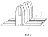
- Figure 1 shows the basic structure of a ribbon cable 1, which consists of a Carrier film 2 exists on which a conductor track 3 (or several conductor tracks 3 in parallel to each other) are arranged.
- a ribbon cable 1 which consists of a Carrier film 2 exists on which a conductor track 3 (or several conductor tracks 3 in parallel to each other) are arranged.
- a wedge-shaped Plastic part 4 arranged on the carrier film 2 (for example by gluing or Injection).
- the structure created in this way represents a plug, whereby at least in a partial area of the plastic part 4 the ones lying there Conductors are exposed.
- the conductor tracks 3 In the remaining area of the ribbon cable 1 are the conductor tracks 3 either exposed or as a rule of one Protected cover film.
- Figure 2 shows two correspondingly constructed ribbon cable 1, each of one have their own plastic parts 4 and 5, the two plastic parts 4 and 5 be joined together so that a shaped and trained according to Figure 2 Connector is created.
- this connector has at least one Plastic part a locking hook 6 with which this connector in its counterpart is fixable.
- the two plastic parts 4 and 5 are also used, for example Locking hooks mechanically connected to each other or can also be glued or the like are connected together.
- FIG. 3 shows the way in which a connector is manufactured, as was shown in FIG. 1.
- the plastic part 4 has two halves 7 and 8, which are in the form of a film hinge are trained. With these two halves 7 and 8, the carrier film 2 of a single ribbon cable 1 or the end region of the carrier film from connected to several ribbon cables. After this is done, the two Halves 7 and 8 brought together to form (dashed) plastic part 4 (wedge-shaped) and form the connector as shown in Figure 1.
- the two halves 7 and 8 are connected to each other by force and / or positive locking and keep the shown shape after matching.
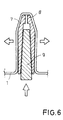
- a connector is shown again, in which the plastic part 4 in turn consists of two Halves 7 and 8 exist, but are movable relative to each other.
- the 6 configured plug inserted into a socket designed according to Figure 4 has been introduced, a spacer between the two halves 7 and 8, the the conductor tracks of the plug against the corresponding conductor tracks of the socket presses.
- the spacer is designed, for example, as a wedge 9, which after its insertion is fixable in position, which can be done for example by gluing.
- the spacer element it is possible for the spacer element to be designed as a spring element, in this way to tolerances and deformations in the operation of the connector to be able to compensate.
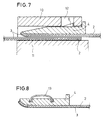
- FIG. 7 shows the use of a plug in a housing (connector housing) by two To connect ribbon cables to each other.
- One is an overhead ribbon cable again provided with its plastic part 4, which has a in its end region has raised edge to better the shaped connector into the housing to be able to introduce.
- the second flat ribbon cable lies approximately plane-parallel in the housing on, the two ribbon cables are to be aligned in such a way that the corresponding conductor tracks 3 lie opposite or one above the other.
- the housing the plug-in connection consists in particular of an upper housing part 10 and a Lower housing part 11, these two parts of the housing forming a slot which take the plug (with the plastic part 4).
- the ribbon cable below is also inserted into this slot and fixed in position. This fixation can for example, that the plastic part 4 with its ribbon cable in introduced the area between the upper housing part 10 and the lower housing part 11 and presses on the ribbon cable underneath.
- the upper housing part 10 also has a recess 12 which is connected to the latching hook 6 the plastic part 4 corresponds to the position fixation of the same.
- Figure 8 shows a connector, in which again a plastic part 4 on the carrier film 2 of the Ribbon cable is arranged.
- the plastic part 4 has a spring element 13 with which it faces one another outer component, in particular a housing (for example upper housing part 10), supports.
- the spring element 13 is designed, for example, as a metal bow spring, can also be made in one piece with the plastic part 4.
- Others too geometric shapes of the spring element 13, such as. B. are a protruding tab possible.
- Figure 9 shows an example of a plurality of ribbon cables 1, each with at their end Plastic parts 4 are provided to form a plug or a socket. Because of the formation of a film hinge 14 between the two halves of the plastic part 4 and depending on the orientation of the angle of the film hinge 4, the ribbon cable 1, which should have different installation directions when installed, first in be made in one direction, the later laying direction from the Angle of the film hinge 14 results. For fixing the position of the ribbon cable 1 or its Plastic parts 4 in the later installed state, the plastic parts 4 have fasteners on, which are designed for example as fastening tabs 15.
- Figure 10 shows different options, such as different electrical devices 16 to 18 (for example sensors, actuators and / or control units or the like) with the plugs or sockets according to the invention with one another by means of ribbon cable 1 can be connected.
- a ribbon cable z. B. connector 19 for Available which are designed according to the geometry shown in Figure 1.
- Such Plugs 19 correspond to sockets 20 which have the geometric shape according to FIG. 4 correspond.
- corresponding ones can also be made on the ribbon cable 1 involved Plugs 19 or sockets 20 may be arranged.
- the associated ribbon cable 1 with a plug 21 is provided, which corresponds to the configuration according to FIG. 7 or Figure 8 is formed.
- a socket 22 in the device 18 (or on this device) available, which is designed according to the configuration shown in Figure 7. It can also be seen that depending on the orientation of the angle of the film hinge 14 (see. Figure 9) the laying direction of the ribbon cable 1 can be varied, but this does not depend on is limited to a right angle, but any angle corresponding to that Installation situation are realizable.
Landscapes
- Coupling Device And Connection With Printed Circuit (AREA)
- Multi-Conductor Connections (AREA)
- Details Of Connecting Devices For Male And Female Coupling (AREA)
Abstract
Description
- Figur 1
- den prinzipiellen Aufbau einer Steckverbindung an einem Flachbandkabel,
- Figur 2
- die Verbindung zweier Flachbandkabel,
- Figur 3
- Herstellungsschritte der Steckverbindung gemäß Figur 1,
- Figuren 4 und 5
- eine erfindungsgemäß hergestellte Buchse und deren Herstellungsschritte,
- Figur 6
- ein Kunststoffteil mit einem eingeschobenen Keil,
- Figur 7
- eine erfindungsgemäß hergestellte Steckverbindung innerhalb eines Gehäuses,
- Figur 8
- eine Steckverbindung mit einem Federelement,
- Figur 9
- die Verlegemöglichkeit von mehreren Flachbandkabeln,
- Figur 10
- unterschiedliche Steckverbindermöglichkeiten zwischen mehreren elektrischen Geräten.
Claims (9)
- Elektrisches Flachbandkabel (1) mit zumindest einer auf einem Träger, insbesondere einer Trägerfolie (2) angeordneten flachen elektrischen Leiterbahn (3), dadurch gekennzeichnet, daß an dem Träger ein Kunststoffteil (4, 5) derart angeordnet ist, daß das Kunststoffteil (4, 5) zusammen mit einem Teil der Leiterbahn (3) einen Stecker (19, 21) oder eine Buchse (20, 22) bildet.
- Elektrisches Flachbandkabel (1) nach Anspruch 1, dadurch gekennzeichnet, daß das Kunststoffteil (4, 5) aus zwei Hälften (7, 8) besteht, die nach dem Anbringen des Trägers zu dem Kunststoffteil (4, 5) zusammengebracht werden und den Stecker (19, 21) bilden.
- Elektrisches Flachbandkabel (1) nach Anspruch 1, dadurch gekennzeichnet, daß das Kunststoffteil (4, 5) aus zwei Hälften (7, 8) besteht, die nach dem Anbringen des Trägers derart auf Distanz zusammengebracht werden, daß sie die Buchse (20, 22) bilden.
- Elektrisches Flachbandkabel (1) nach Anspruch 2, dadurch gekennzeichnet, daß zwischen den beiden Hälften (7, 8) des Steckers (19, 21) ein Distanzelement einbringbar ist.
- Elektrisches Flachbandkabel (1) nach Anspruch 4, dadurch gekennzeichnet, daß das Distanzelement ein Keil (9) und/oder ein Federelement ist.
- Elektrisches Flachbandkabel (1) nach einem der vorhergehenden Ansprüche, dadurch gekennzeichnet, daß das Kunststoffteil (4, 5) ein Verriegelungselement, insbesondere einen Rasthaken (6), aufweist.
- Elektrisches Flachbandkabel (1) nach einem der vorhergehenden Ansprüche, dadurch gekennzeichnet, daß das Kunststoffteil (4, 5) ein Federelement (13) aufweist, mit dem es sich gegenüber einem äußeren Bauteil, insbesondere einem Gehäuse, abstützt.
- Elektrisches Flachbandkabel (1) nach einem der vorhergehenden Ansprüche, dadurch gekennzeichnet, daß das Kunststoffteil (4, 5) ein Filmscharnier (14) aufweist.
- Elektrisches Flachbandkabel (1) nach einem der vorhergehenden Ansprüche, dadurch gekennzeichnet, daß das Kunststoffteil (4, 5) Befestigungsmittel, insbesondere zumindest eine Befestigungslasche (15) aufweist.
Applications Claiming Priority (4)
| Application Number | Priority Date | Filing Date | Title |
|---|---|---|---|
| DE10009976 | 2000-03-03 | ||
| DE10009976 | 2000-03-03 | ||
| DE10104357A DE10104357A1 (de) | 2000-03-03 | 2001-02-01 | Elektrisches Flachbandkabel mit einem Stecker oder einer Buchse |
| DE10104357 | 2001-02-01 |
Publications (3)
| Publication Number | Publication Date |
|---|---|
| EP1130686A2 true EP1130686A2 (de) | 2001-09-05 |
| EP1130686A3 EP1130686A3 (de) | 2002-04-17 |
| EP1130686B1 EP1130686B1 (de) | 2003-10-08 |
Family
ID=26004619
Family Applications (1)
| Application Number | Title | Priority Date | Filing Date |
|---|---|---|---|
| EP01104346A Expired - Lifetime EP1130686B1 (de) | 2000-03-03 | 2001-02-23 | Elektrisches Flachbandkabel mit einem Stecker oder einer Buchse |
Country Status (3)
| Country | Link |
|---|---|
| EP (1) | EP1130686B1 (de) |
| AT (1) | ATE251809T1 (de) |
| ES (1) | ES2208476T3 (de) |
Family Cites Families (3)
| Publication number | Priority date | Publication date | Assignee | Title |
|---|---|---|---|---|
| JPS5726306Y2 (de) * | 1978-04-20 | 1982-06-08 | ||
| JPH0635413Y2 (ja) * | 1989-07-10 | 1994-09-14 | ホシデン株式会社 | コネクタ |
| JPH09129324A (ja) * | 1995-10-31 | 1997-05-16 | Whitaker Corp:The | 電気コネクタ |
-
2001
- 2001-02-23 AT AT01104346T patent/ATE251809T1/de not_active IP Right Cessation
- 2001-02-23 EP EP01104346A patent/EP1130686B1/de not_active Expired - Lifetime
- 2001-02-23 ES ES01104346T patent/ES2208476T3/es not_active Expired - Lifetime
Also Published As
| Publication number | Publication date |
|---|---|
| EP1130686A3 (de) | 2002-04-17 |
| ES2208476T3 (es) | 2004-06-16 |
| ATE251809T1 (de) | 2003-10-15 |
| EP1130686B1 (de) | 2003-10-08 |
Similar Documents
| Publication | Publication Date | Title |
|---|---|---|
| EP1145610B1 (de) | Elektronisches steuergerät | |
| EP2728982B1 (de) | Leiterplattenbaugruppe für ein Steuergerät, Steuergerät für ein Kraftfahrzeug und Signalverarbeitungsanordnung | |
| EP0924971B1 (de) | Anordnung zur Kontaktierung von Leiterplatten | |
| DE102009046014B4 (de) | Elektrisches Verbindergehäuse und Verfahren zu dessen Zusammenbau | |
| EP2481126B1 (de) | Multi fork einpresspin | |
| DE19832011B4 (de) | Flachbandleitung mit einem zum lösbaren Verbinden vorgesehenen Anschlußbereich | |
| EP2728983A1 (de) | Leiterplattenbaugruppe für ein Steuergerät, Steuergerät für ein Kraftfahrzeug und Signalverarbeitungsanordnung | |
| DE102005009443A1 (de) | Folienantenne für ein Fahrzeug | |
| DE102012218433B4 (de) | Kontaktanordnung | |
| DE68910252T2 (de) | Gehäuse für elektronische Schaltungen, insbesondere für Kraftfahrzeuge. | |
| DE102016107898B4 (de) | Laterale Leiterplattenverbindung | |
| DE69839421T2 (de) | Elektrisches verbindungsgehäuse | |
| DE102006011262A1 (de) | Elektrischer Verbinder und Verfahren zu dessen Herstellung | |
| EP1130686B1 (de) | Elektrisches Flachbandkabel mit einem Stecker oder einer Buchse | |
| DE10348045A1 (de) | Elektrischer Verbinder für flexiblen Flachleiter und Schaltvorrichtung | |
| EP1130687B1 (de) | Elektrisches Flachbandkabel mit gefalteten elektrischen Leiterbahnen | |
| DE10104357A1 (de) | Elektrisches Flachbandkabel mit einem Stecker oder einer Buchse | |
| EP1162694B1 (de) | Vorrichtung zum Verbinden von elektrischen Leitern | |
| WO2022189046A1 (de) | Steckervorrichtung zum befestigen von elektronischen komponenten auf einer leiterplatte | |
| DE10134958A1 (de) | Leiterplatine | |
| DE3831961A1 (de) | Halter fuer hybridplatten mit elektronischen bauelementen | |
| EP1396909A1 (de) | Kabelzugentlastung | |
| DE102009008352B4 (de) | Steckverbindungsvorrichtung für eine elektronische Baugruppe | |
| DE202018107302U1 (de) | LED-Leiterplattenmodul und Leuchtensystem | |
| WO1998036474A1 (de) | Anschlusselement |
Legal Events
| Date | Code | Title | Description |
|---|---|---|---|
| PUAI | Public reference made under article 153(3) epc to a published international application that has entered the european phase |
Free format text: ORIGINAL CODE: 0009012 |
|
| AK | Designated contracting states |
Kind code of ref document: A2 Designated state(s): AT DE ES FR GB IT Kind code of ref document: A2 Designated state(s): AT BE CH CY DE DK ES FI FR GB GR IE IT LI LU MC NL PT SE TR |
|
| AX | Request for extension of the european patent |
Free format text: AL;LT;LV;MK;RO;SI |
|
| PUAL | Search report despatched |
Free format text: ORIGINAL CODE: 0009013 |
|
| AK | Designated contracting states |
Kind code of ref document: A3 Designated state(s): AT BE CH CY DE DK ES FI FR GB GR IE IT LI LU MC NL PT SE TR |
|
| AX | Request for extension of the european patent |
Free format text: AL;LT;LV;MK;RO;SI |
|
| RIC1 | Information provided on ipc code assigned before grant |
Free format text: 7H 01R 12/08 A, 7H 01R 12/26 B |
|
| 17P | Request for examination filed |
Effective date: 20020613 |
|
| 17Q | First examination report despatched |
Effective date: 20020809 |
|
| AKX | Designation fees paid |
Free format text: AT DE ES FR GB IT |
|
| GRAH | Despatch of communication of intention to grant a patent |
Free format text: ORIGINAL CODE: EPIDOS IGRA |
|
| GRAS | Grant fee paid |
Free format text: ORIGINAL CODE: EPIDOSNIGR3 |
|
| GRAA | (expected) grant |
Free format text: ORIGINAL CODE: 0009210 |
|
| AK | Designated contracting states |
Kind code of ref document: B1 Designated state(s): AT DE ES FR GB IT |
|
| REG | Reference to a national code |
Ref country code: GB Ref legal event code: FG4D Free format text: NOT ENGLISH |
|
| GBT | Gb: translation of ep patent filed (gb section 77(6)(a)/1977) |
Effective date: 20031008 |
|
| REG | Reference to a national code |
Ref country code: IE Ref legal event code: FG4D Free format text: GERMAN |
|
| REF | Corresponds to: |
Ref document number: 50100733 Country of ref document: DE Date of ref document: 20031113 Kind code of ref document: P |
|
| REG | Reference to a national code |
Ref country code: ES Ref legal event code: FG2A Ref document number: 2208476 Country of ref document: ES Kind code of ref document: T3 |
|
| ET | Fr: translation filed | ||
| REG | Reference to a national code |
Ref country code: IE Ref legal event code: FD4D |
|
| RAP2 | Party data changed (patent owner data changed or rights of a patent transferred) |
Owner name: HIRSCHMANN AUTOMOTIVE GMBH |
|
| PLBE | No opposition filed within time limit |
Free format text: ORIGINAL CODE: 0009261 |
|
| STAA | Information on the status of an ep patent application or granted ep patent |
Free format text: STATUS: NO OPPOSITION FILED WITHIN TIME LIMIT |
|
| 26N | No opposition filed |
Effective date: 20040709 |
|
| PGFP | Annual fee paid to national office [announced via postgrant information from national office to epo] |
Ref country code: AT Payment date: 20050211 Year of fee payment: 5 |
|
| PGFP | Annual fee paid to national office [announced via postgrant information from national office to epo] |
Ref country code: GB Payment date: 20050214 Year of fee payment: 5 |
|
| PG25 | Lapsed in a contracting state [announced via postgrant information from national office to epo] |
Ref country code: IT Free format text: LAPSE BECAUSE OF NON-PAYMENT OF DUE FEES Effective date: 20050223 |
|
| PG25 | Lapsed in a contracting state [announced via postgrant information from national office to epo] |
Ref country code: AT Free format text: LAPSE BECAUSE OF NON-PAYMENT OF DUE FEES Effective date: 20060223 Ref country code: GB Free format text: LAPSE BECAUSE OF NON-PAYMENT OF DUE FEES Effective date: 20060223 |
|
| GBPC | Gb: european patent ceased through non-payment of renewal fee |
Effective date: 20060223 |
|
| PGFP | Annual fee paid to national office [announced via postgrant information from national office to epo] |
Ref country code: DE Payment date: 20140219 Year of fee payment: 14 |
|
| PGFP | Annual fee paid to national office [announced via postgrant information from national office to epo] |
Ref country code: ES Payment date: 20140226 Year of fee payment: 14 Ref country code: FR Payment date: 20140219 Year of fee payment: 14 |
|
| REG | Reference to a national code |
Ref country code: DE Ref legal event code: R119 Ref document number: 50100733 Country of ref document: DE |
|
| REG | Reference to a national code |
Ref country code: FR Ref legal event code: ST Effective date: 20151030 |
|
| PG25 | Lapsed in a contracting state [announced via postgrant information from national office to epo] |
Ref country code: DE Free format text: LAPSE BECAUSE OF NON-PAYMENT OF DUE FEES Effective date: 20150901 |
|
| PG25 | Lapsed in a contracting state [announced via postgrant information from national office to epo] |
Ref country code: FR Free format text: LAPSE BECAUSE OF NON-PAYMENT OF DUE FEES Effective date: 20150302 |
|
| REG | Reference to a national code |
Ref country code: ES Ref legal event code: FD2A Effective date: 20160329 |
|
| PG25 | Lapsed in a contracting state [announced via postgrant information from national office to epo] |
Ref country code: ES Free format text: LAPSE BECAUSE OF NON-PAYMENT OF DUE FEES Effective date: 20150224 |