EP1130687A2 - Cable plat électrique avec trajets pliés électriquement conducteurs - Google Patents
Cable plat électrique avec trajets pliés électriquement conducteurs Download PDFInfo
- Publication number
- EP1130687A2 EP1130687A2 EP01104347A EP01104347A EP1130687A2 EP 1130687 A2 EP1130687 A2 EP 1130687A2 EP 01104347 A EP01104347 A EP 01104347A EP 01104347 A EP01104347 A EP 01104347A EP 1130687 A2 EP1130687 A2 EP 1130687A2
- Authority
- EP
- European Patent Office
- Prior art keywords
- conductor track
- ribbon cable
- conductor
- connector
- exposed
- Prior art date
- Legal status (The legal status is an assumption and is not a legal conclusion. Google has not performed a legal analysis and makes no representation as to the accuracy of the status listed.)
- Granted
Links
Images



Classifications
-
- H—ELECTRICITY
- H01—ELECTRIC ELEMENTS
- H01R—ELECTRICALLY-CONDUCTIVE CONNECTIONS; STRUCTURAL ASSOCIATIONS OF A PLURALITY OF MUTUALLY-INSULATED ELECTRICAL CONNECTING ELEMENTS; COUPLING DEVICES; CURRENT COLLECTORS
- H01R12/00—Structural associations of a plurality of mutually-insulated electrical connecting elements, specially adapted for printed circuits, e.g. printed circuit boards [PCB], flat or ribbon cables, or like generally planar structures, e.g. terminal strips, terminal blocks; Coupling devices specially adapted for printed circuits, flat or ribbon cables, or like generally planar structures; Terminals specially adapted for contact with, or insertion into, printed circuits, flat or ribbon cables, or like generally planar structures
- H01R12/50—Fixed connections
- H01R12/59—Fixed connections for flexible printed circuits, flat or ribbon cables or like structures
- H01R12/592—Fixed connections for flexible printed circuits, flat or ribbon cables or like structures connections to contact elements
-
- H—ELECTRICITY
- H01—ELECTRIC ELEMENTS
- H01R—ELECTRICALLY-CONDUCTIVE CONNECTIONS; STRUCTURAL ASSOCIATIONS OF A PLURALITY OF MUTUALLY-INSULATED ELECTRICAL CONNECTING ELEMENTS; COUPLING DEVICES; CURRENT COLLECTORS
- H01R4/00—Electrically-conductive connections between two or more conductive members in direct contact, i.e. touching one another; Means for effecting or maintaining such contact; Electrically-conductive connections having two or more spaced connecting locations for conductors and using contact members penetrating insulation
- H01R4/10—Electrically-conductive connections between two or more conductive members in direct contact, i.e. touching one another; Means for effecting or maintaining such contact; Electrically-conductive connections having two or more spaced connecting locations for conductors and using contact members penetrating insulation effected solely by twisting, wrapping, bending, crimping, or other permanent deformation
- H01R4/18—Electrically-conductive connections between two or more conductive members in direct contact, i.e. touching one another; Means for effecting or maintaining such contact; Electrically-conductive connections having two or more spaced connecting locations for conductors and using contact members penetrating insulation effected solely by twisting, wrapping, bending, crimping, or other permanent deformation by crimping
- H01R4/183—Electrically-conductive connections between two or more conductive members in direct contact, i.e. touching one another; Means for effecting or maintaining such contact; Electrically-conductive connections having two or more spaced connecting locations for conductors and using contact members penetrating insulation effected solely by twisting, wrapping, bending, crimping, or other permanent deformation by crimping for cylindrical elongated bodies, e.g. cables having circular cross-section
- H01R4/184—Electrically-conductive connections between two or more conductive members in direct contact, i.e. touching one another; Means for effecting or maintaining such contact; Electrically-conductive connections having two or more spaced connecting locations for conductors and using contact members penetrating insulation effected solely by twisting, wrapping, bending, crimping, or other permanent deformation by crimping for cylindrical elongated bodies, e.g. cables having circular cross-section comprising a U-shaped wire-receiving portion
- H01R4/185—Electrically-conductive connections between two or more conductive members in direct contact, i.e. touching one another; Means for effecting or maintaining such contact; Electrically-conductive connections having two or more spaced connecting locations for conductors and using contact members penetrating insulation effected solely by twisting, wrapping, bending, crimping, or other permanent deformation by crimping for cylindrical elongated bodies, e.g. cables having circular cross-section comprising a U-shaped wire-receiving portion combined with a U-shaped insulation-receiving portion
Definitions
- the invention relates to an electrical ribbon cable with at least one on one Carrier, in particular a carrier film, arranged flat electrical conductor track according to the features of the preamble of claim 1.
- Such electrical ribbon cables are known and are used wherever not enough space is available for standard round cables, which also go also have a higher weight compared to ribbon cables.
- To contact such ribbon cables with other ribbon cables or with electrical, Electronic or similar devices or modules require the ribbon cable to be provided with a connector.
- For contacting the conductor tracks with a connector it is known that the conductor track is soldered to the connector becomes. Since the ribbon cable, especially when used in harsh environmental conditions, tensile or compressive forces also act on the conductor track strain relief is provided in the form of one on the connector arranged tab is at least partially placed around the conductor track and on a way that is mechanically deformed that this tab the conductor track pierces.
- the invention is therefore based on the object of having an electrical ribbon cable to provide a connector with which the above described Disadvantages are avoided.
- the conductor track is at least partially at one end is exposed in an electrically conductive manner and is folded over at least once, the exposed one and folded end with a connector, in particular a plug or Socket is connected.
- a connector in particular a plug or Socket is connected.
- This increases the otherwise very thin cross section of the Conductor, so that a higher current flow due to the increased cable cross section is possible, but due to the enlarged cross section also a higher one mechanical stability for contacting the connector is available.
- soldering or similar processes can advantageously be avoided, so that the conductor track only by mechanical deformation of part of the Connector is connected.
- the folding of the conductor track in the contact area has furthermore the advantage that the superimposed conductor track sections before external influences, especially moisture and temperature influences, are protected, so that the contact security is improved.
- the connector has a crimp contact, wherein the exposed and folded end of the conductor track by mechanical deformation of the Crimp contact is set in this. Due to the mechanical deformation of the Crimp contacts is given strain relief on the one hand, so that further means for a Strain relief can be omitted, but not necessarily.
- the mechanical Forming in such a way that the area of the folded-over conductor track sections (where in particular there are also carrier and / or cover foils in between can be pressed together by the crimp contact (or more), whereby contact security increases further. It also folds the area Conductor sections enclosed by the crimp contact, so that a contact area arises from external influences, in particular moisture and temperature influences, is protected. Depending on the design of the crimp contact can also be achieved be that this contact area is completely gastight.
- the exposed end of the conductor track becomes multiple folded over. This increases the cable cross-section in the contact area with the Connector, so that the contact reliability is further improved. Moreover the multiple folding has the advantage that overall due to the otherwise right thin conductor tracks, a thicker end of the ribbon cable is available, which in handling, in particular in contacting with the connector, leads to a simplification.
- the conductor track is exposed on both sides. Consists the ribbon cable from a plurality of interconnects arranged in parallel to each other are arranged on the one hand on a carrier film and on the other hand by a cover film are advantageously protected from folding and contacting the connector the end areas of one or more conductor tracks both from the Carrier film as well as the cover film freed, so that only the complete electrical conductive area of the conductor track comes into contact. Alternatively, it is possible that the conductor track is only exposed on one side, d. that is, either the Carrier film or the cover film remains on the conductor track. This reduces the Most of the effort involved in preparing the ribbon cable for contacting constant contact security.
- a conductor track with a plug connector connected so that after connecting the folded conductor tracks with the Connectors at one end of the ribbon cable several parallel to each other arranged connectors are available. These can be in an associated Contact partners are inserted, it being used to improve handling and Avoid touching the individual connector means are provided able to keep the parallel connectors at a distance. This can be done in particular that several connectors, especially all Connectors that are connected to the conductor tracks are surrounded by a housing become.
- This housing can for example consist of two halves, the Plug connector inserted into one half of the housing and through the second half of the housing be determined. Alternatively, it is conceivable that the individual connectors in their position relative to each other and then overmolded with plastic.
- the connector has wings that according to the mechanical forming the conductor track on the connector, without the To pierce the conductor track. This makes another one in addition to the crimp contact Strain relief given that the contact area of the crimp contact before pull and Relieves pressure forces without mechanically damaging the conductor track.
- FIG. 1 shows the various steps involved in making a ribbon cable to be provided with a connector in the manner according to the invention.
- a ribbon cable 1 has at least one conductor track 2, usually several Conductor tracks 2 are arranged parallel to one another and form the ribbon cable 1.
- These conductor tracks 2 are covered and located on the one hand by a cover film 3 on the other hand on a carrier film 4, the cover film 3 and the carrier film 4 being made of may consist of different or the same material and the same or different are fat.
- a first step the conductor track 2 on both sides of the Cover film 3 and freed from the carrier film 4.
- this will be exposed end of the conductor track 2 folded over and in a third step the end area of the conductor track which has been folded over is folded over again.
- the outermost conductor packet is folded over again, so that a End of trace 2 is available, which now consists of five superimposed Conductor sections exist.
- a connector 5 which is contacted with the conductor track end prepared in this way should consist, for example, of a contact pin 6 and has a barb 7 provided, which prevents the connector 5 after insertion into a Housing (not shown here) can be pulled out of this. Furthermore points the connector 5 has a crimp contact 8, in the area of which the folded end of the Track 2 is inserted. The contacting in this area of the crimp contact 8 will be described for Figures 3 and 4. Another, shown at the bottom right in FIG. 1 Connector 5 can additionally have a strain relief 9, which by mechanical forming around the end region of the ribbon cable 1 with cover film 3 and Carrier film 4 is placed to realize a further strain relief without that Ribbon cable 1 is mechanically damaged. Such strain relief 9 can, must but not be provided on the connector 5.
- Figure 2 shows in the upper and middle third of a ribbon cable 1, in which the The conductor track is freed from its cover film 3, but the carrier film 4 is still present.
- a four-layer cross section 10 results or a double-layer cross section 11 of the end region of the conductor track 2, also even more than one or two folds and also other folds than they are described in Figures 1 and 2, are conceivable.
- the connector 5 with which the folded area of the conductor track 2 should be connected.
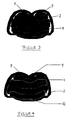
- FIGS. 3 and 4 show a section through the area of the crimp contact 8 of contacting.
- the layers alternate a conductor track 2 and a carrier film 4 (FIG. 3) or the same Layers lie one above the other (see FIG. 4), this being the double-layer cross section 11 corresponds to the middle illustration in FIG. 2.
- the crimp contact 8 before contacting was open at the top and has two wing-like configurations, in front of the Contacting the folded end region of the conductor track 2 in the area of the wing-like Refinements is used and these wing-like configurations in the shown manner are mechanically reshaped, so that ultimately the Crimp contact 8 defines the conductor track package and makes electrical contact. Due to the Design of the crimp contact 8 are the conductor track sections (and, if necessary the foils in between) are compressed, creating a gas-tight seal and reliable connection results.
- FIG. 5 shows, in addition to a first ribbon cable 1, a further ribbon cable 13, which also has at least one conductor track 14 and corresponding cover films 15 and carrier foils 16.
- the correspondingly prepared ends of the conductor tracks 2 and 14 are folded together (as shown in Figure 5) or individually folded and then into a contact area 17, i.e. H. inside the crimp contact 8.
- the mechanical deformation of the crimp contact takes place, so that the conductor tracks 2 and 14 in the contact area 17 mechanically and be electrically connected to each other.
Landscapes
- Coupling Device And Connection With Printed Circuit (AREA)
- Multi-Conductor Connections (AREA)
- Insulated Conductors (AREA)
Applications Claiming Priority (4)
| Application Number | Priority Date | Filing Date | Title |
|---|---|---|---|
| DE10016260 | 2000-03-03 | ||
| DE10016260 | 2000-03-03 | ||
| DE10104354 | 2001-02-01 | ||
| DE10104354A DE10104354A1 (de) | 2000-03-03 | 2001-02-01 | Elektrisches Flachbandkabel mit gefalteten elektrischen Leiterbahnen |
Publications (3)
| Publication Number | Publication Date |
|---|---|
| EP1130687A2 true EP1130687A2 (fr) | 2001-09-05 |
| EP1130687A3 EP1130687A3 (fr) | 2004-10-13 |
| EP1130687B1 EP1130687B1 (fr) | 2006-05-03 |
Family
ID=26005139
Family Applications (1)
| Application Number | Title | Priority Date | Filing Date |
|---|---|---|---|
| EP01104347A Expired - Lifetime EP1130687B1 (fr) | 2000-03-03 | 2001-02-23 | Cable plat électrique avec trajets pliés électriquement conducteurs |
Country Status (4)
| Country | Link |
|---|---|
| EP (1) | EP1130687B1 (fr) |
| AT (1) | ATE325444T1 (fr) |
| DE (2) | DE10104354A1 (fr) |
| ES (1) | ES2263521T3 (fr) |
Cited By (2)
| Publication number | Priority date | Publication date | Assignee | Title |
|---|---|---|---|---|
| EP2339592A3 (fr) * | 2009-12-23 | 2011-12-14 | Hitachi-LG Data Storage Korea, Inc. | Câble, connecteur de câble et ensemble de câble |
| US20140318849A1 (en) * | 2012-01-18 | 2014-10-30 | Yazaki Corporation | Flat circuit body with terminal and manufacturing method thereof |
Families Citing this family (3)
| Publication number | Priority date | Publication date | Assignee | Title |
|---|---|---|---|---|
| DE10213757A1 (de) * | 2001-04-07 | 2003-01-30 | Wet Automotive Systems Ag | Kabel und Herstellungsverfahren |
| JP4376682B2 (ja) * | 2004-04-09 | 2009-12-02 | 矢崎総業株式会社 | 電線端部の加締構造 |
| DE102010005021A1 (de) * | 2010-01-19 | 2011-07-21 | Continental Automotive GmbH, 30165 | Flachleitervorrichtung und elektrischer Energiespeicher |
Family Cites Families (3)
| Publication number | Priority date | Publication date | Assignee | Title |
|---|---|---|---|---|
| BE791001A (fr) * | 1971-11-08 | 1973-05-07 | Amp Inc | Cable electrique plat |
| US5040997A (en) * | 1990-06-08 | 1991-08-20 | The Foxboro Company | Flex circuit connector assembly and method for manufacturing the same |
| DE9414307U1 (de) * | 1994-08-23 | 1994-12-08 | Thomas & Betts Corp., Memphis, Tenn. | Flach/Rundkabelverbindungsvorrichtung |
-
2001
- 2001-02-01 DE DE10104354A patent/DE10104354A1/de not_active Withdrawn
- 2001-02-23 ES ES01104347T patent/ES2263521T3/es not_active Expired - Lifetime
- 2001-02-23 EP EP01104347A patent/EP1130687B1/fr not_active Expired - Lifetime
- 2001-02-23 DE DE50109660T patent/DE50109660D1/de not_active Expired - Lifetime
- 2001-02-23 AT AT01104347T patent/ATE325444T1/de not_active IP Right Cessation
Cited By (3)
| Publication number | Priority date | Publication date | Assignee | Title |
|---|---|---|---|---|
| EP2339592A3 (fr) * | 2009-12-23 | 2011-12-14 | Hitachi-LG Data Storage Korea, Inc. | Câble, connecteur de câble et ensemble de câble |
| US20140318849A1 (en) * | 2012-01-18 | 2014-10-30 | Yazaki Corporation | Flat circuit body with terminal and manufacturing method thereof |
| US10085340B2 (en) * | 2012-01-18 | 2018-09-25 | Yazaki Corporation | Flat circuit body with terminal and manufacturing method thereof |
Also Published As
| Publication number | Publication date |
|---|---|
| EP1130687A3 (fr) | 2004-10-13 |
| DE50109660D1 (de) | 2006-06-08 |
| EP1130687B1 (fr) | 2006-05-03 |
| ATE325444T1 (de) | 2006-06-15 |
| ES2263521T3 (es) | 2006-12-16 |
| DE10104354A1 (de) | 2001-09-06 |
Similar Documents
| Publication | Publication Date | Title |
|---|---|---|
| DE102010031416B4 (de) | Kartenrandverbinder und Verfahren zu dessen Fertigung | |
| DE69406146T2 (de) | Das übersprechen vermindernder verbinder | |
| DE3127704C2 (de) | Verbinder zum Anschließen eines Vielleiter-Flachkabels | |
| DE102010029682B4 (de) | Kartenrandverbinder und Verfahren für dessen Zusammenbau | |
| EP2728982A1 (fr) | Composant à plaquettes pour un appareil de commande, appareil de commande pour un véhicule automobile et agencement de traitement du signal | |
| EP0756244A2 (fr) | Unité électronique et procédé de fabrication de cette unité | |
| DE68912540T2 (de) | Elektrische Kontakte. | |
| EP2979333B1 (fr) | Connecteur à compensation de diaphonie | |
| EP1743402A1 (fr) | Broche pour liaison electrique sans etain comprenant une plaque conductrice, outil d'estampage et procede pour produire une liaison electrique sans etain | |
| DE102016111565A1 (de) | Elektrisches Leiteranschlusselement | |
| EP2728983A1 (fr) | Composant à plaquettes pour un appareil de commande, appareil de commande pour un véhicule automobile et agencement de traitement du signal | |
| DE102021117180A1 (de) | Elektrischer Anschluss für flexible Flachkabel | |
| DE69010397T2 (de) | Elektrische Verbindungsvorrichtung. | |
| EP1130687B1 (fr) | Cable plat électrique avec trajets pliés électriquement conducteurs | |
| DE10134944A1 (de) | Elektrische Anschlußklemme | |
| DE102012218433B4 (de) | Kontaktanordnung | |
| DE102021117178A1 (de) | Elektrischer Anschluss für flexible Flachkabel | |
| DE69303462T2 (de) | Elektrischer Verbinder mit verbesserter Kontakthalterung | |
| DE102006011262A1 (de) | Elektrischer Verbinder und Verfahren zu dessen Herstellung | |
| EP2367202B1 (fr) | Procédé de fabrication d'une connexion électrique entre un contact et un contre-contact | |
| EP3740050B1 (fr) | Carte de circuit imprimé dotée d'un connecteur enfichable | |
| EP1083627B1 (fr) | Connecteur électrique | |
| DE102021117179A1 (de) | Elektrischer Anschluss für flexible Flachkabel | |
| WO2013117419A1 (fr) | Dispositif de mesure de pression pour un capteur de pression d'espace de combustion | |
| DE19738588B4 (de) | Elektrisches Bauelement mit einer Umhüllung und mit einem in der Umhüllung angeordneten Anschlußbereich und Verfahren zur Herstellung eines solchen elektrischen Bauelements |
Legal Events
| Date | Code | Title | Description |
|---|---|---|---|
| PUAI | Public reference made under article 153(3) epc to a published international application that has entered the european phase |
Free format text: ORIGINAL CODE: 0009012 |
|
| AK | Designated contracting states |
Kind code of ref document: A2 Designated state(s): AT BE CH CY DE DK ES FI FR GB GR IE IT LI LU MC NL PT SE TR |
|
| AX | Request for extension of the european patent |
Free format text: AL;LT;LV;MK;RO;SI |
|
| RAP1 | Party data changed (applicant data changed or rights of an application transferred) |
Owner name: HIRSCHMANN AUTOMOTIVE GMBH |
|
| PUAL | Search report despatched |
Free format text: ORIGINAL CODE: 0009013 |
|
| AK | Designated contracting states |
Kind code of ref document: A3 Designated state(s): AT BE CH CY DE DK ES FI FR GB GR IE IT LI LU MC NL PT SE TR |
|
| AX | Request for extension of the european patent |
Extension state: AL LT LV MK RO SI |
|
| 17P | Request for examination filed |
Effective date: 20050108 |
|
| 17Q | First examination report despatched |
Effective date: 20050519 |
|
| AKX | Designation fees paid |
Designated state(s): AT DE ES FR GB IT |
|
| GRAP | Despatch of communication of intention to grant a patent |
Free format text: ORIGINAL CODE: EPIDOSNIGR1 |
|
| GRAS | Grant fee paid |
Free format text: ORIGINAL CODE: EPIDOSNIGR3 |
|
| GRAA | (expected) grant |
Free format text: ORIGINAL CODE: 0009210 |
|
| AK | Designated contracting states |
Kind code of ref document: B1 Designated state(s): AT DE ES FR GB IT |
|
| PG25 | Lapsed in a contracting state [announced via postgrant information from national office to epo] |
Ref country code: IT Free format text: LAPSE BECAUSE OF FAILURE TO SUBMIT A TRANSLATION OF THE DESCRIPTION OR TO PAY THE FEE WITHIN THE PRESCRIBED TIME-LIMIT;WARNING: LAPSES OF ITALIAN PATENTS WITH EFFECTIVE DATE BEFORE 2007 MAY HAVE OCCURRED AT ANY TIME BEFORE 2007. THE CORRECT EFFECTIVE DATE MAY BE DIFFERENT FROM THE ONE RECORDED. Effective date: 20060503 Ref country code: GB Free format text: LAPSE BECAUSE OF FAILURE TO SUBMIT A TRANSLATION OF THE DESCRIPTION OR TO PAY THE FEE WITHIN THE PRESCRIBED TIME-LIMIT Effective date: 20060503 |
|
| REG | Reference to a national code |
Ref country code: GB Ref legal event code: FG4D Free format text: NOT ENGLISH |
|
| REF | Corresponds to: |
Ref document number: 50109660 Country of ref document: DE Date of ref document: 20060608 Kind code of ref document: P |
|
| ET | Fr: translation filed | ||
| GBV | Gb: ep patent (uk) treated as always having been void in accordance with gb section 77(7)/1977 [no translation filed] |
Effective date: 20060503 |
|
| REG | Reference to a national code |
Ref country code: ES Ref legal event code: FG2A Ref document number: 2263521 Country of ref document: ES Kind code of ref document: T3 |
|
| PLBE | No opposition filed within time limit |
Free format text: ORIGINAL CODE: 0009261 |
|
| STAA | Information on the status of an ep patent application or granted ep patent |
Free format text: STATUS: NO OPPOSITION FILED WITHIN TIME LIMIT |
|
| 26N | No opposition filed |
Effective date: 20070206 |
|
| PG25 | Lapsed in a contracting state [announced via postgrant information from national office to epo] |
Ref country code: AT Free format text: LAPSE BECAUSE OF NON-PAYMENT OF DUE FEES Effective date: 20070223 |
|
| REG | Reference to a national code |
Ref country code: FR Ref legal event code: PLFP Year of fee payment: 16 |
|
| REG | Reference to a national code |
Ref country code: FR Ref legal event code: PLFP Year of fee payment: 17 |
|
| PGFP | Annual fee paid to national office [announced via postgrant information from national office to epo] |
Ref country code: DE Payment date: 20170217 Year of fee payment: 17 Ref country code: FR Payment date: 20170217 Year of fee payment: 17 |
|
| PGFP | Annual fee paid to national office [announced via postgrant information from national office to epo] |
Ref country code: ES Payment date: 20170213 Year of fee payment: 17 Ref country code: IT Payment date: 20170221 Year of fee payment: 17 |
|
| REG | Reference to a national code |
Ref country code: DE Ref legal event code: R119 Ref document number: 50109660 Country of ref document: DE |
|
| REG | Reference to a national code |
Ref country code: FR Ref legal event code: ST Effective date: 20181031 |
|
| PG25 | Lapsed in a contracting state [announced via postgrant information from national office to epo] |
Ref country code: DE Free format text: LAPSE BECAUSE OF NON-PAYMENT OF DUE FEES Effective date: 20180901 |
|
| PG25 | Lapsed in a contracting state [announced via postgrant information from national office to epo] |
Ref country code: FR Free format text: LAPSE BECAUSE OF NON-PAYMENT OF DUE FEES Effective date: 20180228 Ref country code: IT Free format text: LAPSE BECAUSE OF NON-PAYMENT OF DUE FEES Effective date: 20180223 |
|
| REG | Reference to a national code |
Ref country code: ES Ref legal event code: FD2A Effective date: 20190801 |
|
| PG25 | Lapsed in a contracting state [announced via postgrant information from national office to epo] |
Ref country code: ES Free format text: LAPSE BECAUSE OF NON-PAYMENT OF DUE FEES Effective date: 20180224 |