EP1130741A2 - Pompe avec rotor d'entrainement situé du coté aspiration - Google Patents
Pompe avec rotor d'entrainement situé du coté aspiration Download PDFInfo
- Publication number
- EP1130741A2 EP1130741A2 EP01102363A EP01102363A EP1130741A2 EP 1130741 A2 EP1130741 A2 EP 1130741A2 EP 01102363 A EP01102363 A EP 01102363A EP 01102363 A EP01102363 A EP 01102363A EP 1130741 A2 EP1130741 A2 EP 1130741A2
- Authority
- EP
- European Patent Office
- Prior art keywords
- pump
- impeller
- rotor
- housing
- hydraulic insert
- Prior art date
- Legal status (The legal status is an assumption and is not a legal conclusion. Google has not performed a legal analysis and makes no representation as to the accuracy of the status listed.)
- Withdrawn
Links
Images
Classifications
-
- F—MECHANICAL ENGINEERING; LIGHTING; HEATING; WEAPONS; BLASTING
- F04—POSITIVE - DISPLACEMENT MACHINES FOR LIQUIDS; PUMPS FOR LIQUIDS OR ELASTIC FLUIDS
- F04D—NON-POSITIVE-DISPLACEMENT PUMPS
- F04D29/00—Details, component parts, or accessories
- F04D29/04—Shafts or bearings, or assemblies thereof
- F04D29/046—Bearings
- F04D29/047—Bearings hydrostatic; hydrodynamic
-
- F—MECHANICAL ENGINEERING; LIGHTING; HEATING; WEAPONS; BLASTING
- F04—POSITIVE - DISPLACEMENT MACHINES FOR LIQUIDS; PUMPS FOR LIQUIDS OR ELASTIC FLUIDS
- F04D—NON-POSITIVE-DISPLACEMENT PUMPS
- F04D13/00—Pumping installations or systems
- F04D13/02—Units comprising pumps and their driving means
- F04D13/06—Units comprising pumps and their driving means the pump being electrically driven
- F04D13/0646—Units comprising pumps and their driving means the pump being electrically driven the hollow pump or motor shaft being the conduit for the working fluid
-
- H—ELECTRICITY
- H02—GENERATION; CONVERSION OR DISTRIBUTION OF ELECTRIC POWER
- H02K—DYNAMO-ELECTRIC MACHINES
- H02K5/00—Casings; Enclosures; Supports
- H02K5/04—Casings or enclosures characterised by the shape, form or construction thereof
- H02K5/12—Casings or enclosures characterised by the shape, form or construction thereof specially adapted for operating in liquid or gas
- H02K5/128—Casings or enclosures characterised by the shape, form or construction thereof specially adapted for operating in liquid or gas using air-gap sleeves or air-gap discs
-
- H—ELECTRICITY
- H02—GENERATION; CONVERSION OR DISTRIBUTION OF ELECTRIC POWER
- H02K—DYNAMO-ELECTRIC MACHINES
- H02K7/00—Arrangements for handling mechanical energy structurally associated with dynamo-electric machines, e.g. structural association with mechanical driving motors or auxiliary dynamo-electric machines
- H02K7/08—Structural association with bearings
- H02K7/086—Structural association with bearings radially supporting the rotor around a fixed spindle; radially supporting the rotor directly
- H02K7/088—Structural association with bearings radially supporting the rotor around a fixed spindle; radially supporting the rotor directly radially supporting the rotor directly
Definitions
- the present invention relates to one operated by an electric motor Wet rotor pump, in particular a centrifugal pump, having a can, the between a hydraulic insert rotating in the pump medium and a Stator is arranged, the hydraulic insert mounted in bearings the impeller and a rotor which extends the suction mouth of the impeller and carries the rotor Includes hollow shaft and wherein the rotor in the direction of flow in front of the impeller is arranged.
- Canned motor pumps are in different designs and with different nominal powers well known. All known pumps have basically the same design, in which the hydraulic side and the Drive side structurally separated one behind the other and by one Containment can are hydraulically separated.
- a fundamental disadvantage of these pumps is that it is because of the losses in efficiency caused by the containment shell of the electric drive is necessary, correspondingly stronger drives to compensate for this disadvantage compared to dry-running. This problem contributes to the fact that such canned motor pumps in comparison a larger installation space for wet rotor pumps with the same nominal output need.
- wet-running pumps have a comparative pump great axial length.
- the object of the present invention is therefore to provide such an electrical To operate operated wet running pump, which can be small in size and particularly simple construction due to high reliability and above all through low manufacturing costs.
- the particularly advantageous small dimensions of the pump result first from the fact that the rotor "on the suction side" before and not in relation to the Suction nozzle is arranged behind the impeller.
- the suction side rotor enables a particularly compact design of the pump, in which the pump housing according to the invention is provided with a central opening. In this opening is the hydraulic insert can be inserted in the axial direction. It is in the pump housing a first bearing accommodating the hydraulic insert is arranged. The opening is closable with a housing cover, the housing cover being a second has the bearing receiving the hydraulic insert.
- the in known pumps required electrical drive part almost completely, the in a, usually cylindrical, housing located behind the impeller is.
- the electrical drive is now carried out by means of a rotor which opens at the front the impeller is arranged.
- the invention is advantageously used in centrifugal pumps, the Impeller is designed so that it has a cylindrical hollow shaft that is coaxial surrounds the centrally arranged suction mouth and which are of sufficient Length is to carry the permanent magnets required for the rotor.
- This Construction favors the arrangement according to the invention in a special way of the rotor between the suction nozzle and the impeller.
- the the impeller designed the suction mouth through which the pump medium flows Hollow shaft designed to carry the rotor.
- the hollow shaft and the Intake sockets have the same inner diameter. So that can Pump medium undisturbed via the somewhat extended suction port in enter the impeller and from there it is transported to the discharge port.
- the particular advantage of the pump according to the invention lies in the compact design with a relatively short overall length.
- Such a pump is also particularly inexpensive because of its simple structure Manufacturing.
- the pump is particularly suitable for the Use in cooling circuits of motor vehicles.
- the structure according to the invention the pump thereby makes it particularly easy to maintain and Reliability of the pump.
- the pump can only three components put together, one designed as a receptacle Component the pump housing surrounding the impeller chamber with the is formed on the nozzle.
- the stator can be in this first component incorporated, for example injected.
- This first component forms as Includes a bearing for the second component, the impeller with it length-shaped rotor.
- the recording is on the back of the third component, a cover, which is a second bearing for the impeller trains.
- the pump Impeller with the hollow shaft surrounding the suction mouth in one piece, in particular made of plastic and thus form a compact hydraulic insert, so the second component.
- the hydraulic insert is advantageously designed so that that it can accommodate the permanent magnet surrounding the hollow shaft.
- the permanent magnet in the material of the hydraulic insert embedded, in particular poured.
- hydraulic insert on the back of the impeller is also advantageous to use to be provided with a journal so that the hydraulic insert between two Plain bearings can be arranged.
- a hydraulic insert thus contains all components required for the function of the pump and thus contributes a further simplification of the pump construction.
- Such hydraulic inserts can also be provided with different impeller geometries, so that the pump with a depending on the intended use Hydraulic insert can be equipped.
- Another advantage of the pump according to the invention is that there are no dead spaces are present in which pump medium remains with a low exchange rate, such as it was previously the case in the poorly flushed canisters. So you can There are no deposits of ingredients in the pump in the pump medium are present, which lead to a further increase in reliability and contributes to the life of the pump according to the invention.
- the pump has one-piece, essentially rotationally symmetrical pump housing, at which the suction pipe, the can and the impeller chamber in axial alignment are arranged one behind the other.
- This pump housing can advantageously be made in one piece from plastic, which further reduces the Manufacturing costs and the weight of the pump contributes.
- the impeller housing is a radially protruding pressure connection appropriate. This very simplified pump housing in its construction ensures a particular with the hydraulic insert according to the invention structurally particularly simple pump.
- the opening of the Pump housing closed with a housing cover, which is advantageous detachable, for example via a screw or snap connection with the Pump housing is connected.
- This housing cover has a special simple embodiment of a cylindrical receptacle in which the Back of the impeller arranged by means of a plain bearing is used.
- the interior is over the housing cover according to the invention the pump is accessible at all times, so that defective components are easy are interchangeable.
- the Pump according to the invention only from three, at most four components, the rotating hydraulic insert via two plain bearings between the pump housing and the housing cover is held.
- the pump constructed in this way stands out due to their special compactness and is due to the small number Components particularly robust and reliable.
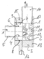
- the figure shows a canned motor pump operated by an electric motor an impeller 2 arranged in an impeller chamber 1.
- the impeller chamber 1 is surrounded by a pump housing 3, to which a coaxial to the suction mouth 4th of the impeller 2 aligned suction nozzle 5 is formed.
- the pump medium is fed to the suction nozzle in the direction of arrow A.
- the suction mouth 4 of the Pump wheel 2 surrounds a cylindrical hollow shaft 6, on which a rotor 7 does not permanent magnet shown is held.
- the magnets are in that Poured in material of the rotor.
- Impeller 2, hollow shaft 6 and rotor 7 form one one-piece hydraulic insert.
- On the suction port 5 facing away Back of the pump housing 3, this has an opening 17 into which the Hydraulic insert in the axial direction (against arrow A) can be inserted.
- the Pump housing forms a first bearing receiving the hydraulic insert.
- the rotor is that of the one with permanent magnets surrounding hollow shaft 6 is formed in the direction of flow (arrow A) before Impeller 2 and arranged behind the suction nozzle 5.
- the rotor runs in a can 8 formed by a wall of the one-piece housing 3 becomes.
- the inner diameter of the suction nozzle 5 corresponds to that Inner diameter of the hollow shaft 6 and thus that of the suction mouth 4.
- the impeller 2 and the rotor 7 seated on the hollow shaft 6 are in one piece formed a hydraulic insert, which in the interior of the pump housing 3 in first slide bearing 9 is inserted.
- the hydraulic insert points to the back of the impeller 2 on a bearing pin 10 which by means of a slide ring 11 in a second bearing designed as a receptacle is used.
- the second camp is molded onto a housing cover 13 closing the opening 17.
- the Housing cover 13 is against a via a seal, not shown Housing 3 sealed.
- the pumped medium pumped by the impeller 2 leaves the Housing 3 via a pressure port aligned perpendicular to the suction port 5 14 (arrow B).
- the rotor 7 rotatably mounted in the can 8 is from one to the can 8
- the stator windings, not shown, are connected via a plug 16 contacted with the supply voltage.
- the pump can be built so compact that the axial Expansion of the impeller corresponds approximately to the axial expansion of the rotor.
Landscapes
- Engineering & Computer Science (AREA)
- Mechanical Engineering (AREA)
- General Engineering & Computer Science (AREA)
- Power Engineering (AREA)
- Physics & Mathematics (AREA)
- Fluid Mechanics (AREA)
- Structures Of Non-Positive Displacement Pumps (AREA)
Applications Claiming Priority (2)
| Application Number | Priority Date | Filing Date | Title |
|---|---|---|---|
| DE10009376 | 2000-02-29 | ||
| DE2000109376 DE10009376A1 (de) | 2000-02-29 | 2000-02-29 | Saugseitiger Rotor |
Publications (2)
| Publication Number | Publication Date |
|---|---|
| EP1130741A2 true EP1130741A2 (fr) | 2001-09-05 |
| EP1130741A3 EP1130741A3 (fr) | 2003-11-19 |
Family
ID=7632723
Family Applications (1)
| Application Number | Title | Priority Date | Filing Date |
|---|---|---|---|
| EP01102363A Withdrawn EP1130741A3 (fr) | 2000-02-29 | 2001-02-02 | Pompe avec rotor d'entrainement situé du coté aspiration |
Country Status (2)
| Country | Link |
|---|---|
| EP (1) | EP1130741A3 (fr) |
| DE (1) | DE10009376A1 (fr) |
Cited By (8)
| Publication number | Priority date | Publication date | Assignee | Title |
|---|---|---|---|---|
| WO2004044433A1 (fr) * | 2002-11-05 | 2004-05-27 | BSH Bosch und Siemens Hausgeräte GmbH | Pompe a entrainement electrique |
| WO2004044434A1 (fr) * | 2002-11-05 | 2004-05-27 | BSH Bosch und Siemens Hausgeräte GmbH | Pompe a entrainement electrique |
| WO2013107807A2 (fr) | 2012-01-20 | 2013-07-25 | Yasa Motors Poland Sp. Z O.O. | Pompe a rotor noyé |
| DE102012200806A1 (de) * | 2012-01-20 | 2013-07-25 | Yasa Motors Poland Sp. z.o.o. | Nassläuferpumpe mit Leistungselektronik |
| DE102012200816A1 (de) * | 2012-01-20 | 2013-07-25 | Yasa Motors Poland Sp. z.o.o. | Nassläuferpumpe mit Permantmagnet |
| DE102012200807A1 (de) * | 2012-01-20 | 2013-07-25 | Yasa Motors Poland Sp. z.o.o. | Nassläuferpumpe mit Gleitlager |
| EP2735744A3 (fr) * | 2012-11-23 | 2017-08-16 | Wilo Ag | Roue mobile d'une pompe centrifuge à aimants |
| CN109185178A (zh) * | 2018-10-31 | 2019-01-11 | 芜湖飞龙汽车电子技术研究院有限公司 | 一种车辆用电子水泵 |
Families Citing this family (3)
| Publication number | Priority date | Publication date | Assignee | Title |
|---|---|---|---|---|
| DE102012209487A1 (de) * | 2012-06-05 | 2013-12-05 | Mahle International Gmbh | Hydrodynamische Pumpe |
| DE102013200655B4 (de) * | 2013-01-17 | 2015-11-05 | Yasa Motors Poland Sp. z.o.o. | Kombiniertes Radial-Axiallager und Nassläuferpumpe |
| DE102016219273A1 (de) * | 2016-10-05 | 2018-04-05 | Bayerische Motoren Werke Aktiengesellschaft | Elektrische Pumpe für ein Fahrzeug, insbesondere für ein Kraftfahrzeug, sowie Fahrzeug |
Family Cites Families (10)
| Publication number | Priority date | Publication date | Assignee | Title |
|---|---|---|---|---|
| US2524269A (en) * | 1946-10-14 | 1950-10-03 | Sta Rite Products Inc | Pump |
| BE534251A (fr) * | 1953-12-21 | |||
| FR1134967A (fr) * | 1955-10-20 | 1957-04-23 | Moteur électrique à rotor libre pour groupe électro-pompe | |
| DE1118340B (de) * | 1960-02-23 | 1961-11-30 | Hans Moser Dr Ing | Verringerung der Lagerbelastung bei in Fluessigkeit umlaufenden Elektromotoren durch Ausbildung des Rotors als Schwimmkoerper |
| US3291056A (en) * | 1965-04-22 | 1966-12-13 | William W Steinman | Electric motor pump |
| FR2608228B1 (fr) * | 1986-12-12 | 1991-07-19 | Valeo | Pompe a liquide, notamment pompe a eau, en particulier pour vehicules automobiles |
| US5288215A (en) * | 1992-11-19 | 1994-02-22 | Chancellor Dennis H | Integral motor centrifugal pump |
| DE4434448C2 (de) * | 1994-09-27 | 1996-10-17 | Richard Halm | Naßläufer-Spaltrohrmotor für Pumpen |
| DE19538278A1 (de) * | 1995-10-15 | 1996-05-02 | Sbs Sondermaschinen Gmbh | Umwälzpumpe mit Elektroantrieb |
| EP0844723A3 (fr) * | 1996-11-25 | 1999-05-06 | ATB Austria Antriebstechnik Aktiengesellschaft | Pompe entraínée par un moteur électrique |
-
2000
- 2000-02-29 DE DE2000109376 patent/DE10009376A1/de not_active Withdrawn
-
2001
- 2001-02-02 EP EP01102363A patent/EP1130741A3/fr not_active Withdrawn
Cited By (18)
| Publication number | Priority date | Publication date | Assignee | Title |
|---|---|---|---|---|
| WO2004044433A1 (fr) * | 2002-11-05 | 2004-05-27 | BSH Bosch und Siemens Hausgeräte GmbH | Pompe a entrainement electrique |
| WO2004044434A1 (fr) * | 2002-11-05 | 2004-05-27 | BSH Bosch und Siemens Hausgeräte GmbH | Pompe a entrainement electrique |
| US7131823B2 (en) | 2002-11-05 | 2006-11-07 | Bsh Bosch Und Siemens Hausgeraete Gmbh | Electrically driven pump and domestic appliance having the pump |
| CN100400892C (zh) * | 2002-11-05 | 2008-07-09 | Bsh博施及西门子家用器具有限公司 | 电驱动的泵 |
| CN100443732C (zh) * | 2002-11-05 | 2008-12-17 | Bsh博施及西门子家用器具有限公司 | 电动泵 |
| WO2013107807A2 (fr) | 2012-01-20 | 2013-07-25 | Yasa Motors Poland Sp. Z O.O. | Pompe a rotor noyé |
| DE102012200806A1 (de) * | 2012-01-20 | 2013-07-25 | Yasa Motors Poland Sp. z.o.o. | Nassläuferpumpe mit Leistungselektronik |
| DE102012200816A1 (de) * | 2012-01-20 | 2013-07-25 | Yasa Motors Poland Sp. z.o.o. | Nassläuferpumpe mit Permantmagnet |
| DE102012200807A1 (de) * | 2012-01-20 | 2013-07-25 | Yasa Motors Poland Sp. z.o.o. | Nassläuferpumpe mit Gleitlager |
| DE102012200803A1 (de) * | 2012-01-20 | 2013-07-25 | Yasa Motors Poland Sp. z.o.o. | Nassläuferpumpe |
| DE102012200816A8 (de) * | 2012-01-20 | 2013-09-26 | Yasa Motors Poland Sp. z.o.o. | Nassläuferpumpe mit Permanentmagnet |
| WO2013107805A3 (fr) * | 2012-01-20 | 2013-12-19 | Yasa Motors Poland Sp. Z O.O. | Pompe à rotor noyé comportant une électronique de puissance |
| DE102012200806B4 (de) * | 2012-01-20 | 2014-07-31 | Yasa Motors Poland Sp. z.o.o. | Nassläuferpumpe mit Leistungselektronik |
| DE102012200807B4 (de) * | 2012-01-20 | 2014-09-25 | Yasa Motors Poland Sp. z.o.o. | Nassläuferpumpe mit Gleitlager |
| DE102012200803B4 (de) * | 2012-01-20 | 2015-04-02 | Yasa Motors Poland Sp. z.o.o. | Nassläuferpumpe |
| DE102012200816B4 (de) * | 2012-01-20 | 2015-04-02 | Yasa Motors Poland Sp. z.o.o. | Nassläuferpumpe mit Permanentmagnet |
| EP2735744A3 (fr) * | 2012-11-23 | 2017-08-16 | Wilo Ag | Roue mobile d'une pompe centrifuge à aimants |
| CN109185178A (zh) * | 2018-10-31 | 2019-01-11 | 芜湖飞龙汽车电子技术研究院有限公司 | 一种车辆用电子水泵 |
Also Published As
| Publication number | Publication date |
|---|---|
| DE10009376A1 (de) | 2001-08-30 |
| EP1130741A3 (fr) | 2003-11-19 |
Similar Documents
| Publication | Publication Date | Title |
|---|---|---|
| EP1191232B1 (fr) | Pompe de refroidissement à entraînement électrique | |
| EP1995426A1 (fr) | Moteur électrique | |
| DE10352487A1 (de) | Pumpe mit integriertem Motor | |
| DE102012111150A1 (de) | Elektrische Wasserpumpe | |
| DE19705974A1 (de) | Elektromotor für eine Pumpe oder einen Lüfter | |
| DE3107845C2 (fr) | ||
| EP1573207A1 (fr) | Pompe a entrainement electrique | |
| DE102006034354A1 (de) | Elektropumpe | |
| DE10009376A1 (de) | Saugseitiger Rotor | |
| DE102009056240A1 (de) | Antriebsendblock für eine Magnetronanordnung mit einem rotierenden Target | |
| DE3152000A1 (de) | Elektrisch betaetigbare fluessigkeitspumpe | |
| DE19943862A1 (de) | Naßläuferpumpe mit Montageplatte | |
| DE202017006981U1 (de) | Verbesserter Elektromotor für einen Fluidzirkulator | |
| DE102017215107A1 (de) | Pumpe | |
| DE19725941A1 (de) | Förderaggregat für Kraftstoff | |
| DE19921365B4 (de) | Elektromagnetisch betriebene Pumpe mit Axialspaltlager | |
| DE102007049209B4 (de) | Gleichstrommotor | |
| EP1081386B1 (fr) | Moteur électrique a flux axial | |
| DE19721108A1 (de) | Kraftstoffpumpe und Verfahren zur Herstellung dergleichen | |
| WO2005028936A1 (fr) | Dispositif de positionnement de clapet | |
| EP1343645B1 (fr) | Appareil de chauffage automobile comportant une pompe de recirculation de caloporteur integree | |
| WO1988003993A1 (fr) | Pompe pour milieux liquides | |
| EP1567772A1 (fr) | Pompe a entrainement electrique | |
| DE102005001697B4 (de) | Elektrischer Motor und Fluidpumpe, die diesen verwendet | |
| DE102006058837C5 (de) | Schmiermittelgedichtete Drehschiebervakuumpumpe |
Legal Events
| Date | Code | Title | Description |
|---|---|---|---|
| PUAI | Public reference made under article 153(3) epc to a published international application that has entered the european phase |
Free format text: ORIGINAL CODE: 0009012 |
|
| AK | Designated contracting states |
Kind code of ref document: A2 Designated state(s): AT BE CH CY DE DK ES FI FR GB GR IE IT LI LU MC NL PT SE TR |
|
| AX | Request for extension of the european patent |
Free format text: AL;LT;LV;MK;RO;SI |
|
| PUAL | Search report despatched |
Free format text: ORIGINAL CODE: 0009013 |
|
| AK | Designated contracting states |
Kind code of ref document: A3 Designated state(s): AT BE CH CY DE DK ES FI FR GB GR IE IT LI LU MC NL PT SE TR |
|
| AX | Request for extension of the european patent |
Extension state: AL LT LV MK RO SI |
|
| AKX | Designation fees paid |
Designated state(s): DE FR GB IT |
|
| STAA | Information on the status of an ep patent application or granted ep patent |
Free format text: STATUS: THE APPLICATION IS DEEMED TO BE WITHDRAWN |
|
| 18D | Application deemed to be withdrawn |
Effective date: 20040520 |