EP1130765A2 - Générateur de fréquence variable - Google Patents
Générateur de fréquence variable Download PDFInfo
- Publication number
- EP1130765A2 EP1130765A2 EP01300908A EP01300908A EP1130765A2 EP 1130765 A2 EP1130765 A2 EP 1130765A2 EP 01300908 A EP01300908 A EP 01300908A EP 01300908 A EP01300908 A EP 01300908A EP 1130765 A2 EP1130765 A2 EP 1130765A2
- Authority
- EP
- European Patent Office
- Prior art keywords
- control system
- generator
- main
- output
- winding
- Prior art date
- Legal status (The legal status is an assumption and is not a legal conclusion. Google has not performed a legal analysis and makes no representation as to the accuracy of the status listed.)
- Granted
Links
- 238000004804 winding Methods 0.000 claims abstract description 51
- 238000000034 method Methods 0.000 claims abstract description 7
- 230000001419 dependent effect Effects 0.000 claims description 6
- 238000010586 diagram Methods 0.000 description 5
- 230000001105 regulatory effect Effects 0.000 description 2
- 230000003044 adaptive effect Effects 0.000 description 1
- 230000009286 beneficial effect Effects 0.000 description 1
- 230000001276 controlling effect Effects 0.000 description 1
- 230000008878 coupling Effects 0.000 description 1
- 238000010168 coupling process Methods 0.000 description 1
- 238000005859 coupling reaction Methods 0.000 description 1
- 230000005669 field effect Effects 0.000 description 1
- 238000012423 maintenance Methods 0.000 description 1
- 239000007787 solid Substances 0.000 description 1
- 230000001052 transient effect Effects 0.000 description 1
Images


Classifications
-
- H—ELECTRICITY
- H02—GENERATION; CONVERSION OR DISTRIBUTION OF ELECTRIC POWER
- H02P—CONTROL OR REGULATION OF ELECTRIC MOTORS, ELECTRIC GENERATORS OR DYNAMO-ELECTRIC CONVERTERS; CONTROLLING TRANSFORMERS, REACTORS OR CHOKE COILS
- H02P9/00—Arrangements for controlling electric generators for the purpose of obtaining a desired output
- H02P9/14—Arrangements for controlling electric generators for the purpose of obtaining a desired output by variation of field
- H02P9/26—Arrangements for controlling electric generators for the purpose of obtaining a desired output by variation of field using discharge tubes or semiconductor devices
- H02P9/30—Arrangements for controlling electric generators for the purpose of obtaining a desired output by variation of field using discharge tubes or semiconductor devices using semiconductor devices
- H02P9/305—Arrangements for controlling electric generators for the purpose of obtaining a desired output by variation of field using discharge tubes or semiconductor devices using semiconductor devices controlling voltage
-
- H—ELECTRICITY
- H02—GENERATION; CONVERSION OR DISTRIBUTION OF ELECTRIC POWER
- H02P—CONTROL OR REGULATION OF ELECTRIC MOTORS, ELECTRIC GENERATORS OR DYNAMO-ELECTRIC CONVERTERS; CONTROLLING TRANSFORMERS, REACTORS OR CHOKE COILS
- H02P9/00—Arrangements for controlling electric generators for the purpose of obtaining a desired output
- H02P9/10—Control effected upon generator excitation circuit to reduce harmful effects of overloads or transients, e.g. sudden application of load, sudden removal of load, sudden change of load
- H02P9/102—Control effected upon generator excitation circuit to reduce harmful effects of overloads or transients, e.g. sudden application of load, sudden removal of load, sudden change of load for limiting effects of transients
-
- H—ELECTRICITY
- H02—GENERATION; CONVERSION OR DISTRIBUTION OF ELECTRIC POWER
- H02P—CONTROL OR REGULATION OF ELECTRIC MOTORS, ELECTRIC GENERATORS OR DYNAMO-ELECTRIC CONVERTERS; CONTROLLING TRANSFORMERS, REACTORS OR CHOKE COILS
- H02P2101/00—Special adaptation of control arrangements for generators
- H02P2101/30—Special adaptation of control arrangements for generators for aircraft
Definitions
- the present invention relates to a control system for a variable frequency generator.
- a control system for a variable frequency generator may be used with an aircraft generator driven, for example, by a gas turbine engine.
- a known type of generator for use with an aero-engine is disclosed in GB 1 596 291.
- the generator comprises three stages, each of which has a rotor and a stator with the rotors being attached to a common drive shaft.
- the first stage or pilot exciter comprises a permanent magnet generator having a permanent magnet rotor co-operating with three phase stator windings.
- the stator windings are connected via a rectifier and voltage regulator to the main exciter winding forming the stator of the main exciter.
- the rotor of the main exciter comprises three phase windings which are connected via a rectifier to a rotor winding of the main generator stage, which has three phase stator windings connected to the generator output.
- This arrangement is also applicable to variable frequency machines and DC output machines where the main generator stator winding is connected via a rectifier to give a DC generator output.
- the output voltage of the generator is regulated by comparing the output voltage with a reference and controlling the voltage regulator in order to control the main exciter field.
- the generator must be designed to maintain the nominal output voltage for the full electrical load throughout the operating speed range which may typically be 380 to 780 Hz.
- a known control system of this type has been used to regulate generator operating parameters relating to average generator output voltage, high phase take-over and generator output current. Signals corresponding to each of these parameters are passed through a highest wins circuit, and the winning signal is subject to stability compensation. Stability compensation is provided by a negative feedback signal from the output of the main exciter field drive, the signal being fed back through a stability compensation circuit.
- a control system for a variable frequency generator of the type comprising a main stator winding for providing a generator output, excited by a main rotor winding, and a main exciter rotor winding for energising the main rotor winding, excited by a main exciter field winding
- the control system comprising: a plurality of inputs adapted to receive respective signals corresponding to respective generator operating parameters; an output adapted to drive the main exciter field winding and a plurality of negative feedback loops between the control system output and the inputs, each loop including a respective stability compensation network operable to process a feedback signal corresponding to one of said operating parameters.
- An operating characteristic of at least one of the stability compensation networks may be adaptively controllable in accordance with a present operating frequency of the generator.
- the or each of the adaptively controllable networks may be adaptively controllable in accordance with a predetermined frequency range in which the present operating frequency falls.
- the control system may include sensing means operable to sense a plurality of generator operating parameters and to provide to the respective inputs respective signals corresponding to the operating parameters.
- the sensing means may be operable to provide signals representing average generator output voltage and/or high phase take-over and/or generator output current.
- At least one of the networks may include a switch operable by a frequency dependent input signal.
- the arrangement may be such that, in use, one of said signals corresponding to a generator operating parameter is directed along a first route through the network until the switch is operated so as to cause the signal to be redirected along a different route through the network.
- the signal corresponding to a generator operating parameter can be caused to pass through a selected arrangement of network components appropriate for providing a desired level of stability compensation in accordance with the present operating frequency. Improved stability control is thereby facilitated across a range of operating frequencies.
- The, or each switch may be arranged to operate at a respective predetermined operating frequency.
- Each said network may be provided with a respective said switch, the switches being arranged to operate at a common predetermined operating frequency.
- the control system may be operable to provide signals respectively corresponding to the average voltage of each phase of the generator output and to provide to one of said control system inputs a high phase take-over signal corresponding to the highest of the sensed average voltages.
- This is advantageous over the use of a peak voltage sensing circuit for HPT regulation, as described for example in GB-A-2293704, since the discharge rate of a peak sensing circuit can give different values of ripple on the sensed voltage at different frequencies causing changing levels of regulated voltage as the load increases.
- variations in the peak to RMS ratio of the generator output waveform can occur over the full load and power factor range in a variable frequency control system, and the regulation level is required to remain constant under different operating conditions. Regulators operating on peak sensing give varying RMS levels of regulation as the ratio varies.
- a control system for a variable frequency generator of the type comprising a main stator winding for providing a generator output, excited by a main rotor winding, and a main exciter rotor winding for energising the main rotor winding, excited by a main exciter field winding, the control system comprising an input adapted to receive a signal corresponding to a generator operating parameter; an output adapted to drive the main exciter field winding and a negative feedback loop between the control system output and the input, the loop including a stability compensation network operable to process the signal, an operating characteristic of the stability compensation network being adaptively controllable in accordance with a present operating frequency of the generator.
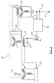
- the aircraft variable frequency electrical generator G shown in Figure 1 comprises a pilot exciter 1 in the form of a permanent magnet generator (PMG) having a permanent magnet rotor 2 and a three phase stator winding 3.
- the stator winding 3 is connected to a generator control unit 4.
- the unit 4 supplies power from the winding 3 to a stator field winding 5 of a main exciter 6.
- the main exciter 6 has a three phase rotor winding 7 connected via a half wave bridge rectifier 8 to a rotor winding 9 of a main rotor of the generator.
- a main stator 10 has a three phase winding which is connected as the output 11.
- the main rotor winding 9 together with the rotor winding 7 and the permanent magnet rotor 2 are fixed to a common shaft 12 so as to rotate together.
- the shaft 12 is connected via a suitable coupling to an aircraft engine.
- the control unit 4 is connected to a generator current transformer 13.
- the transformer 13 senses the current at the output of the generator main stator winding so as to signal along lines 13a to the control unit 4 the output current of the generator and possible fault conditions.
- the control unit 4 has an input connected to the output 11 by a line 15 for sensing the output voltage of the generator.
- the control unit 4 is shown in more detail in Figure 2.
- the main exciter field winding 5 is connected in series with an insulated gate power field effect transistor 20 between a common line and the output of a rectifier 22 whose input is connected to the stator winding 3 of the pilot exciter 1.
- the main exciter field winding 5 is connected in parallel with a diode 23.
- the gate of the transistor 20 is connected to the output of a voltage regulator 24 of the generator control unit 4 for driving the main exciter field winding 5.
- Sensing means in the form of the transformer 13 and the sensing line 15, is connected to inputs of the voltage regulator 24.
- the regulator 24 may comprise a control circuit implemented as an application specific integrated circuit.
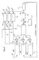
- Figure 3 shows a control system for use in the generator control unit voltage regulator 24.
- Three system inputs 30, 31, 32 are shown respectively corresponding to the operating parameters: generator output current, average generator output voltage and high phase take-over.
- Signals corresponding to these operating parameters are provided using current and voltage signals drawn from the output 11 of the main stator 10 to the inputs 30, 31, 32 using the lines 13a, 15.
- the raw signals may be processed by processing means 30a, 31a, 32a to provide signals in convenient form representing a predetermined generator current limit, average voltage and high phase takeover.
- Negative feedback signals are provided from the output 5a of the main exciter field drive provided by the voltage regulator 24 along respective lines 33, 34, 35 to interact with the input signals 30, 31, 32 at respective summing junctions 33a, 34a and 35a, thus applying negative feedback to each of the three signals routed into a highest wins circuit 36.
- the highest of the resultant signals prevails and is compared with a reference voltage provided by voltage reference means 37.
- the input signal F to the field drive is dependent on the relative difference between the output of the highest wins circuit and the reference voltage. In this manner, the main exciter field can be controlled to thereby control the generator output.
- the feedback signal from the field drive is directed through independent stability compensation networks 38, 39, 40.
- Each network is adapted to provide a desired level of compensation specifically tailored to meet the feedback requirements for the particular feedback signal which it is designed to process. This enables the stability of the control system to be enhanced, which is particularly beneficial in high variable frequency systems where there can be considerable change in the generator transfer function over the frequency and load range.
- Each network 38, 39 40 has a respective input 45, 45a, 45b connected to the field drive output 5a and a respective input 46, 46a, 46b connected to a frequency dependent signal source S controlled by the control system.
- FIG 4 is a schematic diagram of the stability compensation block for processing a feedback signal for the high phase take-over.
- the stability compensation network 38 includes two stability compensation sub-networks A and B.
- An input 45 of the stability compensation network 38 is connected in series with sub-network A or alternatively sub-network B by a switch 44, for example a solid state switch or changeover relay.
- the switch 44 is operable by a signal from an input 46 of the network 38 as indicated by broken line 46a.
- a feedback signal from input 45 is directed through sub-network A to an output 47 of the network 38 until the switch is operated by a signal from input 46 so as to route the feedback signal through sub-network B to output 47.
- the signal for operating the switch 44 is input to input 46 when the operating frequency of the generator reaches a predetermined frequency.
- the generator is designed to operate from 380-780 Hz and means are provided for supplying a frequency dependent input signal for switching switch 44 from sub-network A to sub-network B when the generator speed reaches 580 Hz. This typically changes the feedback time constant by a factor of 3.
- the switch is operable to redirect the feedback signal from a route passing through a first resistor to a route passing through the first resistor in parallel with a second resistor.
- the frequency dependent input signal may be an adaptive gain signal from the microprocessor, the microprocessor being programmed to detect the generator frequency.
- switches and sub-networks may be arranged to be connected into the feedback loop at various respective operating frequencies if required. It will be appreciated that similar switches and sub-networks C/D, E/F can be provided in the networks 39 and 40. Such additional switches and sub-networks can be arranged to provide different levels of stability compensation and/or different switching frequencies depending on the feedback requirements of the loop 33, 34, 35 in which they are incorporated.
Landscapes
- Engineering & Computer Science (AREA)
- Power Engineering (AREA)
- Control Of Eletrric Generators (AREA)
Applications Claiming Priority (2)
| Application Number | Priority Date | Filing Date | Title |
|---|---|---|---|
| GB0004018 | 2000-02-22 | ||
| GBGB0004018.8A GB0004018D0 (en) | 2000-02-22 | 2000-02-22 | Control circuit for electrical generator |
Publications (3)
| Publication Number | Publication Date |
|---|---|
| EP1130765A2 true EP1130765A2 (fr) | 2001-09-05 |
| EP1130765A3 EP1130765A3 (fr) | 2003-01-22 |
| EP1130765B1 EP1130765B1 (fr) | 2006-12-27 |
Family
ID=9886075
Family Applications (1)
| Application Number | Title | Priority Date | Filing Date |
|---|---|---|---|
| EP01300908A Expired - Lifetime EP1130765B1 (fr) | 2000-02-22 | 2001-02-01 | Générateur de fréquence variable |
Country Status (5)
| Country | Link |
|---|---|
| US (1) | US6486640B2 (fr) |
| EP (1) | EP1130765B1 (fr) |
| DE (1) | DE60125444D1 (fr) |
| ES (1) | ES2278689T3 (fr) |
| GB (1) | GB0004018D0 (fr) |
Cited By (2)
| Publication number | Priority date | Publication date | Assignee | Title |
|---|---|---|---|---|
| WO2003041266A1 (fr) * | 2001-11-02 | 2003-05-15 | Honeywell International Inc. | Systeme de commande regulant l'energie d'excitation pour un alternateur generateur synchrone sans balais |
| EP2621044A3 (fr) * | 2012-01-18 | 2013-11-20 | Hamilton Sundstrand Corporation | Protection contre les surtensions lors d'une défaillance GCU |
Families Citing this family (30)
| Publication number | Priority date | Publication date | Assignee | Title |
|---|---|---|---|---|
| US6707276B2 (en) * | 2000-06-26 | 2004-03-16 | Denso Corporation | Voltage regulator of AC generator having circuit for detecting voltage induced in field coil |
| JP4186432B2 (ja) * | 2000-08-08 | 2008-11-26 | 株式会社デンソー | 車両用交流発電機の電圧制御装置 |
| US6555993B2 (en) * | 2000-09-28 | 2003-04-29 | Denso Corporation | Voltage regulating system of a vehicle AC generator for charging a battery |
| JP4333022B2 (ja) * | 2000-11-10 | 2009-09-16 | 株式会社デンソー | 車両用発電機の発電制御システム |
| JP3797201B2 (ja) * | 2001-04-25 | 2006-07-12 | 株式会社デンソー | 車両用発電制御装置 |
| EP1289118A1 (fr) * | 2001-08-24 | 2003-03-05 | Siemens Aktiengesellschaft | Méthode et dispositif pour démarrer un turbogénérateur |
| JP4438260B2 (ja) * | 2001-08-30 | 2010-03-24 | 株式会社デンソー | 車両用発電制御装置 |
| US6628005B2 (en) * | 2001-09-27 | 2003-09-30 | Siemens Westinghouse Power Corporation | Single speed turbine generator for different power system output frequencies in power generation systems and associated methods |
| US6768278B2 (en) * | 2002-08-06 | 2004-07-27 | Honeywell International, Inc. | Gas turbine engine starter generator with switchable exciter stator windings |
| US6850043B1 (en) * | 2003-01-30 | 2005-02-01 | Hamilton Sundstrand Corporation | Excessive voltage protector for a variable frequency generating system |
| US7414331B2 (en) * | 2004-03-31 | 2008-08-19 | General Electric Company | Power converter system and method |
| US7081696B2 (en) | 2004-08-12 | 2006-07-25 | Exro Technologies Inc. | Polyphasic multi-coil generator |
| US20060087293A1 (en) * | 2004-10-26 | 2006-04-27 | Honeywell International, Inc. | AC generator with independently controlled field rotational speed |
| CN101501963B (zh) | 2006-06-08 | 2012-06-13 | Exro技术公司 | 多相多线圈发电机 |
| US7569942B2 (en) * | 2006-07-03 | 2009-08-04 | Honda Motor Co., Ltd. | Output voltage controller of engine-driven generator |
| US7592786B2 (en) * | 2007-08-13 | 2009-09-22 | Honeywell International Inc. | Aircraft engine starter/generator |
| US7915869B2 (en) * | 2008-04-01 | 2011-03-29 | Honeywell International Inc. | Single stage starter/generator with rotor quadrature AC excitation |
| US7671570B2 (en) * | 2008-04-04 | 2010-03-02 | General Electric Company | Systems and methods involving operating variable speed generators |
| US7977925B2 (en) | 2008-04-04 | 2011-07-12 | General Electric Company | Systems and methods involving starting variable speed generators |
| US7466109B1 (en) | 2008-04-07 | 2008-12-16 | General Electric Company | Systems and methods involving variable speed generators |
| US20090273192A1 (en) * | 2008-04-30 | 2009-11-05 | Guven Mustafa K | Doubly fed axial flux induction generator |
| US8198743B2 (en) * | 2009-09-11 | 2012-06-12 | Honeywell International, Inc. | Multi-stage controlled frequency generator for direct-drive wind power |
| NO331113B1 (no) * | 2010-03-23 | 2011-10-10 | Norwegian Ocean Power As | Variabel elektrisk generator |
| US8928293B1 (en) * | 2013-08-02 | 2015-01-06 | Hamilton Sundstrand Corporation | Systems for wound field synchronous machines with zero speed rotor position detection during start for motoring and improved transient response for generation |
| JP2020521418A (ja) | 2017-05-23 | 2020-07-16 | ディーピーエム テクノロジーズ インク. | 可変コイル結線システム |
| US10415530B2 (en) * | 2018-01-16 | 2019-09-17 | The Boeing Company | System and method for operating an independent speed variable frequency generator as a starter |
| US20210249981A1 (en) | 2018-09-05 | 2021-08-12 | Dpm Technologies Inc. | Systems and methods for intelligent control of rotating electric machines |
| WO2020215154A1 (fr) | 2019-04-23 | 2020-10-29 | Dpm Technologies Inc. | Machine électrique rotative tolérante aux défaillances |
| US11897362B2 (en) | 2021-05-04 | 2024-02-13 | Exro Technologies Inc. | Systems and methods for individual control of a plurality of controllable units of battery cells |
| JP2024518405A (ja) | 2021-05-13 | 2024-05-01 | エクスロ テクノロジーズ インク. | 多相電気機械のコイルを駆動する方法及び装置 |
Family Cites Families (14)
| Publication number | Priority date | Publication date | Assignee | Title |
|---|---|---|---|---|
| GB1596291A (en) * | 1977-12-13 | 1981-08-26 | Lucas Industries Ltd | Rotor cooling in a rotary electric machine |
| CA1097738A (fr) * | 1976-08-20 | 1981-03-17 | Westinghouse Electric Corporation | Methode de desexcitation rapide d'une excitatrice sans balai |
| US4179729A (en) * | 1977-04-15 | 1979-12-18 | The Charles Stark Draper Laboratory, Inc. | Rotary electric machine and power conversion system using same |
| US4336486A (en) * | 1980-01-09 | 1982-06-22 | Westinghouse Electric Corp. | Dynamoelectric machines brushless supplemental excitation system |
| US5231344A (en) * | 1990-01-17 | 1993-07-27 | Hitachi Ltd. | Control apparatus for electric generator |
| US5495163A (en) * | 1993-05-12 | 1996-02-27 | Sundstrand Corporation | Control for a brushless generator operable in generating and starting modes |
| US5363032A (en) * | 1993-05-12 | 1994-11-08 | Sundstrand Corporation | Sensorless start of synchronous machine |
| US5493200A (en) * | 1993-05-12 | 1996-02-20 | Sundstrand Corporation | Control for a brushless generator |
| US5753989A (en) * | 1993-06-14 | 1998-05-19 | Ecoair Corp. | Hybrid alternator |
| DE69309667T2 (de) * | 1993-06-25 | 1997-09-04 | Sgs Thomson Microelectronics | Ausgangsstufe unter Verwendung von alternativ MOS oder bipolaren Vorrichtungen, abhängig von der Versorgungsspannung und Regler für einen Drehstromgenerator |
| GB9412410D0 (en) * | 1994-06-21 | 1994-08-10 | Lucas Ind Plc | Control circuit for electrical generator |
| GB2293704B (en) * | 1994-06-21 | 1998-07-29 | Lucas Ind Plc | Control circuit for electrical generator |
| FR2727584A1 (fr) * | 1994-11-30 | 1996-05-31 | Electricite De France | Dispositif de regulation desensibilisee de la tension statorique d'un alternateur |
| US5920162A (en) * | 1996-08-05 | 1999-07-06 | Sundstrand Corporation | Position control using variable exciter feed through |
-
2000
- 2000-02-22 GB GBGB0004018.8A patent/GB0004018D0/en not_active Ceased
-
2001
- 2001-02-01 EP EP01300908A patent/EP1130765B1/fr not_active Expired - Lifetime
- 2001-02-01 ES ES01300908T patent/ES2278689T3/es not_active Expired - Lifetime
- 2001-02-01 DE DE60125444T patent/DE60125444D1/de not_active Expired - Lifetime
- 2001-02-21 US US09/790,224 patent/US6486640B2/en not_active Expired - Lifetime
Cited By (3)
| Publication number | Priority date | Publication date | Assignee | Title |
|---|---|---|---|---|
| WO2003041266A1 (fr) * | 2001-11-02 | 2003-05-15 | Honeywell International Inc. | Systeme de commande regulant l'energie d'excitation pour un alternateur generateur synchrone sans balais |
| US6909262B2 (en) | 2001-11-02 | 2005-06-21 | Honeywell International Inc. | Control system for regulating exciter power for a brushless synchronous generator |
| EP2621044A3 (fr) * | 2012-01-18 | 2013-11-20 | Hamilton Sundstrand Corporation | Protection contre les surtensions lors d'une défaillance GCU |
Also Published As
| Publication number | Publication date |
|---|---|
| DE60125444D1 (de) | 2007-02-08 |
| ES2278689T3 (es) | 2007-08-16 |
| EP1130765B1 (fr) | 2006-12-27 |
| US6486640B2 (en) | 2002-11-26 |
| GB0004018D0 (en) | 2000-04-12 |
| US20010022511A1 (en) | 2001-09-20 |
| EP1130765A3 (fr) | 2003-01-22 |
Similar Documents
| Publication | Publication Date | Title |
|---|---|---|
| EP1130765B1 (fr) | Générateur de fréquence variable | |
| RU2222863C2 (ru) | Система для снабжения электродвигательных потребителей электрической энергии | |
| US4663581A (en) | Voltage regulated permanent magnet generator system | |
| US6724099B2 (en) | Method and apparatus for starting up a turboset | |
| US5013929A (en) | Power conversion system having prime mover start capability | |
| US5029263A (en) | Electric start control of a VSCF system | |
| US4684873A (en) | Hybrid generating system | |
| US9325229B2 (en) | Generator architecture with PMG exciter and main field rotating power converter | |
| JP2007124898A (ja) | 風力発電施設運転方法 | |
| US5479081A (en) | AC motor controller with voltage margin adjustment | |
| US9088230B2 (en) | Dual generator system | |
| US5777459A (en) | Induction electrical power generating system with variable numbers of poles and excitation frequency | |
| GB2458807A (en) | Starting variable speed generators | |
| US20140265747A1 (en) | Epgs architecture with multi-channel synchronous generator and common field regulated exciter | |
| EP0275953B1 (fr) | Système pour générer la puissance par un nombre variable de révolutions | |
| EP1704636B1 (fr) | Procede et appareil de commande de la regulation d'une tension c.a. variable | |
| EP0568262B1 (fr) | Source d'alimentation électrique avec fréquence constante | |
| EP4195493A1 (fr) | Excitation parallèle de la fonction de démarrage de moteur pour générateur synchrone à trois étages | |
| US4937723A (en) | VSCF system with an overload protection | |
| US4888493A (en) | Speed trimming integrated drive generator | |
| US6362588B1 (en) | Excitation system for rotating synchronous machines | |
| EP1638199A1 (fr) | Systeme d'entrainement pour moteurs | |
| US6239583B1 (en) | Regulation system for a permanent magnet generator | |
| US2357086A (en) | Electric ship propulsion system | |
| JP3821592B2 (ja) | 発電機の電圧調整装置 |
Legal Events
| Date | Code | Title | Description |
|---|---|---|---|
| PUAI | Public reference made under article 153(3) epc to a published international application that has entered the european phase |
Free format text: ORIGINAL CODE: 0009012 |
|
| AK | Designated contracting states |
Kind code of ref document: A2 Designated state(s): AT BE CH CY DE DK ES FI FR GB GR IE IT LI LU MC NL PT SE TR |
|
| AX | Request for extension of the european patent |
Free format text: AL;LT;LV;MK;RO;SI |
|
| PUAL | Search report despatched |
Free format text: ORIGINAL CODE: 0009013 |
|
| AK | Designated contracting states |
Kind code of ref document: A3 Designated state(s): AT BE CH CY DE DK ES FI FR GB GR IE IT LI LU MC NL PT SE TR |
|
| AX | Request for extension of the european patent |
Free format text: AL;LT;LV;MK;RO;SI |
|
| RIC1 | Information provided on ipc code assigned before grant |
Free format text: 7H 02P 9/30 A, 7H 02P 9/10 B |
|
| 17P | Request for examination filed |
Effective date: 20030711 |
|
| RAP1 | Party data changed (applicant data changed or rights of an application transferred) |
Owner name: GOODRICH CONTROL SYSTEMS LIMITED |
|
| AKX | Designation fees paid |
Designated state(s): DE ES FR GB IT |
|
| 17Q | First examination report despatched |
Effective date: 20050330 |
|
| GRAP | Despatch of communication of intention to grant a patent |
Free format text: ORIGINAL CODE: EPIDOSNIGR1 |
|
| GRAS | Grant fee paid |
Free format text: ORIGINAL CODE: EPIDOSNIGR3 |
|
| GRAA | (expected) grant |
Free format text: ORIGINAL CODE: 0009210 |
|
| AK | Designated contracting states |
Kind code of ref document: B1 Designated state(s): DE ES FR GB IT |
|
| PG25 | Lapsed in a contracting state [announced via postgrant information from national office to epo] |
Ref country code: IT Free format text: LAPSE BECAUSE OF FAILURE TO SUBMIT A TRANSLATION OF THE DESCRIPTION OR TO PAY THE FEE WITHIN THE PRE;WARNING: LAPSES OF ITALIAN PATENTS WITH EFFECTIVE DATE BEFORE 2007 MAY HAVE OCCURRED AT ANY TIME BEFORE 2007. THE CORRECT EFFECTIVE DATE MAY BE DIFFERENT FROM THE ONE RECORDED.SCRIBED TIME-LIMIT Effective date: 20061227 |
|
| REG | Reference to a national code |
Ref country code: GB Ref legal event code: FG4D |
|
| REF | Corresponds to: |
Ref document number: 60125444 Country of ref document: DE Date of ref document: 20070208 Kind code of ref document: P |
|
| PG25 | Lapsed in a contracting state [announced via postgrant information from national office to epo] |
Ref country code: DE Free format text: LAPSE BECAUSE OF FAILURE TO SUBMIT A TRANSLATION OF THE DESCRIPTION OR TO PAY THE FEE WITHIN THE PRESCRIBED TIME-LIMIT Effective date: 20070328 |
|
| ET | Fr: translation filed | ||
| REG | Reference to a national code |
Ref country code: ES Ref legal event code: FG2A Ref document number: 2278689 Country of ref document: ES Kind code of ref document: T3 |
|
| PLBE | No opposition filed within time limit |
Free format text: ORIGINAL CODE: 0009261 |
|
| STAA | Information on the status of an ep patent application or granted ep patent |
Free format text: STATUS: NO OPPOSITION FILED WITHIN TIME LIMIT |
|
| 26N | No opposition filed |
Effective date: 20070928 |
|
| PGFP | Annual fee paid to national office [announced via postgrant information from national office to epo] |
Ref country code: ES Payment date: 20090317 Year of fee payment: 9 |
|
| REG | Reference to a national code |
Ref country code: ES Ref legal event code: FD2A Effective date: 20110407 |
|
| PG25 | Lapsed in a contracting state [announced via postgrant information from national office to epo] |
Ref country code: ES Free format text: LAPSE BECAUSE OF NON-PAYMENT OF DUE FEES Effective date: 20110328 |
|
| PG25 | Lapsed in a contracting state [announced via postgrant information from national office to epo] |
Ref country code: ES Free format text: LAPSE BECAUSE OF NON-PAYMENT OF DUE FEES Effective date: 20100202 |
|
| REG | Reference to a national code |
Ref country code: FR Ref legal event code: CJ Effective date: 20130617 Ref country code: FR Ref legal event code: CD Owner name: GOODRICH CONTROL SYSTEMS Effective date: 20130617 |
|
| REG | Reference to a national code |
Ref country code: GB Ref legal event code: 732E Free format text: REGISTERED BETWEEN 20140522 AND 20140528 |
|
| REG | Reference to a national code |
Ref country code: FR Ref legal event code: PLFP Year of fee payment: 16 |
|
| REG | Reference to a national code |
Ref country code: FR Ref legal event code: PLFP Year of fee payment: 17 |
|
| REG | Reference to a national code |
Ref country code: FR Ref legal event code: PLFP Year of fee payment: 18 |
|
| PGFP | Annual fee paid to national office [announced via postgrant information from national office to epo] |
Ref country code: GB Payment date: 20200123 Year of fee payment: 20 |
|
| PGFP | Annual fee paid to national office [announced via postgrant information from national office to epo] |
Ref country code: FR Payment date: 20200122 Year of fee payment: 20 |
|
| REG | Reference to a national code |
Ref country code: GB Ref legal event code: PE20 Expiry date: 20210131 |
|
| PG25 | Lapsed in a contracting state [announced via postgrant information from national office to epo] |
Ref country code: GB Free format text: LAPSE BECAUSE OF EXPIRATION OF PROTECTION Effective date: 20210131 |