EP1130800B1 - Allocation asymmétrique de ressources dans un système de communications satellitaires - Google Patents
Allocation asymmétrique de ressources dans un système de communications satellitaires Download PDFInfo
- Publication number
- EP1130800B1 EP1130800B1 EP01103597A EP01103597A EP1130800B1 EP 1130800 B1 EP1130800 B1 EP 1130800B1 EP 01103597 A EP01103597 A EP 01103597A EP 01103597 A EP01103597 A EP 01103597A EP 1130800 B1 EP1130800 B1 EP 1130800B1
- Authority
- EP
- European Patent Office
- Prior art keywords
- uplink
- assignment
- gateway
- assign
- uplinks
- Prior art date
- Legal status (The legal status is an assumption and is not a legal conclusion. Google has not performed a legal analysis and makes no representation as to the accuracy of the status listed.)
- Expired - Lifetime
Links
- 238000004891 communication Methods 0.000 title claims description 76
- 238000000034 method Methods 0.000 claims description 28
- 238000013461 design Methods 0.000 claims description 5
- 239000012141 concentrate Substances 0.000 description 7
- 230000011664 signaling Effects 0.000 description 7
- 238000010586 diagram Methods 0.000 description 4
- 238000009826 distribution Methods 0.000 description 3
- 238000012545 processing Methods 0.000 description 3
- 230000006870 function Effects 0.000 description 2
- 238000012986 modification Methods 0.000 description 2
- 230000004048 modification Effects 0.000 description 2
- 238000013459 approach Methods 0.000 description 1
- 230000005540 biological transmission Effects 0.000 description 1
- 230000001413 cellular effect Effects 0.000 description 1
- 230000007423 decrease Effects 0.000 description 1
- 235000019800 disodium phosphate Nutrition 0.000 description 1
- 238000011156 evaluation Methods 0.000 description 1
- 238000012544 monitoring process Methods 0.000 description 1
- 230000007704 transition Effects 0.000 description 1
- 239000002699 waste material Substances 0.000 description 1
Images


Classifications
-
- H—ELECTRICITY
- H04—ELECTRIC COMMUNICATION TECHNIQUE
- H04B—TRANSMISSION
- H04B7/00—Radio transmission systems, i.e. using radiation field
- H04B7/14—Relay systems
- H04B7/15—Active relay systems
- H04B7/185—Space-based or airborne stations; Stations for satellite systems
- H04B7/18578—Satellite systems for providing broadband data service to individual earth stations
- H04B7/18584—Arrangements for data networking, i.e. for data packet routing, for congestion control
Definitions
- the present invention relates to assignment of bandwidth resources in a communication system.
- the present invention relates to asymmetric assignment of communication bandwidth in a satellite communications system.
- Communication networks transmit and receive staggering amounts of information that may have virtually any origin including, for example, the Internet, the public telephone system, and television stations.
- ISPs Internet service providers
- US 5594940 is an example of a traffic prediction method.
- One aspect of the present invention is asymmetric assignment of bandwidth in a communication system.
- Another aspect of the present invention is asymmetric assignment of uplink and downlink bandwidth in a satellite communication system.
- One feature of the present invention is Assignment of bandwidth in a communication system that considers uplink and downlink utilization efficiencies, outbound to inbound traffic ratio, and other input parameters.
- Yet another feature of the present invention is the assignment of uplink and downlink bandwidth in a satellite communication system that accounts for concentrators onboard a satellite.
- the present method for allocating bandwidth in a satellite communication system includes the step of determining an assignment of uplinks to user terminals and one or more gateways.
- the uplink assignment is preferably based on a gateway uplink efficiency, a user terminal uplink efficiency, and a traffic ratio between the user terminal and the gateways.
- the method also determines an assignment of downlinks to the user terminals and the gateways.
- the downlink assignment is preferably based on traffic offered to the user terminals and the gateways as dictated by the uplink assignment.
- Either of the uplink assignment and downlink assignments may be integer or non-integer assignments. Integer and non-integer assignments may be used when the uplinks and/or downlinks are divisible into assignable subchannels. Integer assignments may be used when the uplinks are indivisible. In some instances, the assignment that maximizes outbound capacity is a non-integer assignment. In cases where the uplinks and downlinks are indivisible, the present method may then evaluate integer assignments of uplinks around the non-integer assignment to determine an integer assignment that most closely matches the maximal outbound capacity.
- the present method in determining the downlink assignments, preferably considers the relative size (i.e., capacity) of uplinks compared to downlinks.
- the method may further determine the desired number of downlinks needed for a gateway and the user terminals to meet the bandwidth demands resulting from the uplink assignments. When the number of available downlinks is sufficient, the method assigns the desired number of downlinks. Otherwise, the method preferably evaluates assignments of downlinks to the user terminals and gateways to find a capacity maximizing downlink assignment given the total number of available downlinks.
- the present satellite communication system bandwidth controller includes uplink and downlink assignment circuitry and communication circuitry.
- the assignment circuitry is operable to determine an assignment of uplinks to user terminals and gateways, based on a gateway uplink efficiency, a user terminal uplink efficiency, and a traffic ratio between the user terminal and the gateway among other information.
- the assignment circuitry is also operable to determine an assignment of downlinks to the user terminals and the gateways, based on traffic offered to the user terminals and the gateways according to the uplink assignment.
- the bandwidth controller may further include input parameter determination circuitry for determining the gateway uplink efficiency, user terminal uplink efficiency, and the traffic ratio, by receiving the parameters as design inputs or by evaluating a communication system monitor input.
- the bandwidth controller may be disposed onboard a satellite, or on the ground at a location nearby or remote from the gateways or user terminals.
- the bandwidth controller evaluates a communication system in operation and responsively dynamically adjusts the uplink and downlink assignments.
- the bandwidth controller evaluates uplink and downlink assignments in advance for a planned communication system.
- the uplink and downlink assignments may be integer or non-integer, and may further take into consideration the presence or absence of a multiplexer or concentrator onboard a satellite.
- the communication system 100 includes a satellite 102, gateway terminals 104, and user terminals 106. Also shown are a controller 108 and a monitor 110.
- the satellite 102 generates a spot beam 112 which supports uplinks and downlinks.
- Figure 1 shows a gateway terminal uplink 114, a gateway terminal downlink 116, a user terminal uplink 118, and a user terminal downlink 120.
- a signaling channel 122 is also present in Figure 1.
- one of the terminals involved in communicating through the satellite 102 is a high throughput terminal called a gateway (e.g., the gateway 104).
- the user terminals are generally smaller individual terminals, for example home computers or cellular phones.
- the user terminals may, for example, represent web browsing individuals and the gateways Internet Service Providers (ISPs).
- ISPs Internet Service Providers
- the user terminals typically send far less traffic to the gateways than the gateways send to the users. Ratios ranging between 5-to-1 and 20-to-1 are not unusual.
- the satellite 102 may be any type of communication satellite.
- the satellite 102 may be a bent-pipe satellite, an analog multiplexer satellite, an analog switch satellite, a digital processing satellite, or a hybrid type.
- the uplinks 114, 118 and downlinks 116, 120 may be of any modulation type and may have any physical make-up and link layer protocols.
- the uplinks may be formed using Frequency Division Multiplexing or Multiple Access (FDM / FDMA), Time Division Multiplexing or Multiple Access (TDM / TDMA), Code Division Multiple Access (CDMA) techniques, or combinations of such access techniques.
- FDM / FDMA Frequency Division Multiplexing or Multiple Access
- TDM / TDMA Time Division Multiplexing or Multiple Access
- CDMA Code Division Multiple Access
- the bandwidth providing individual frequency channels, time slots, or codes may be individually assigned, down to any available level of granularity, as described below, or entire uplinks and downlinks may be assigned as unitary entities constructed from numerous subchannels.
- the bandwidth assignment technique discussed below may further take into consideration features available onboard the satellite in order to maximize the effective capacity of the communication system. For example, when the satellite has a concentrating function such as a statistical multiplexer or concentrator (which removes some or all of the unused bandwidth in the uplinks before putting traffic in the downlinks), the invention may consider the presence of the concentrator in its determination of bandwidth assignments.
- a concentrating function such as a statistical multiplexer or concentrator (which removes some or all of the unused bandwidth in the uplinks before putting traffic in the downlinks)
- An example of bandwidth assignments taking into consideration the presence of a concentrator is set forth below.
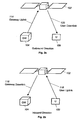
- Figure 2a illustrates a satellite 102 forwarding communications from a gateway 104 to a user terminal 106.
- the direction of traffic flow from the gateway 104 to the user terminal 106 is referred to as the "outbound" direction.
- Traffic flow in the outbound direction travels over the gateway uplink 114 (i.e., the outbound uplink), through the satellite 102, and over the user downlink 120 (i.e., the outbound downlink) to the user terminal 106.
- Figure 2b shows that traffic flow in the "inbound" direction travels over the user uplink 118 (i.e., the inbound uplink), through the satellite 102, and over the gateway downlink 116 (i.e., the inbound downlink) to the gateway 104.
- the gateway downlink 116 i.e., the inbound downlink
- the controller 108 preferably makes and modifies bandwidth assignments, and may also be used in an initial planning role when developing a new communication system. Principal functions of the controller 108 include assigning satellite uplink and downlink bandwidth to the user terminals 106 and the gateways 104 and communicating these assignments to the user terminals 106 and the gateways 104.
- the assignments may be communicated in any number of ways including through terrestrial communication networks. In the preferred embodiment, however, the controller communicates assignments over a signaling channel 122 carried through the satellite 102 to the user terminals 106 and the gateways 104.
- the signaling channel 122 typically uses a very small amount of bandwidth and may be carried, for example, by any available uplink or downlink.
- the monitor 110 periodically evaluates the amount of bandwidth granted to and used by the user terminals 106 and the gateways 104 by using an antenna and processing circuitry or other monitoring hardware/software to evaluate traffic flow.
- the monitor 110 itself is optional.
- the controller 108 may operate using approximations or predetermined values.
- the monitor 110 may, in some instances, form a part of the controller 108 itself, although the monitor 110 may also be implemented as a remotely operating independent device (with appropriate communication connection to the controller 108).
- the controller 108 may make bandwidth assignments (discussed below) at a very fine or a very coarse level of refinement or granularity, depending upon the needs and capabilities of the communication system and the detail of information available.
- a communication system may only include the capability to assign bandwdith on the basis of entire uplinks or downlinks.
- a more sophisticated communication system may include the capability to assign bandwidth in terms of individual channels or subchannels (e.g., codes or time slots) in the uplinks and downlinks.
- the bandwidth assignments described below make the most efficient use of the available bandwidth in light of the granularity constraint imposed by the communication system.
- Table 1 presents the quantities that the controller 108 preferably considers in assigning uplinks and downlinks in its preferred implementation: Table 1 Parameter Description
- R The ratio of outbound to inbound traffic.
- UE gwul The utilization efficiency of the gateway uplinks.
- UE uul The utilization efficiency of the user uplinks.
- UE gwdl The utilization efficiency of the gateway downlinks.
- UE uud1 The utilization efficiency of the user downlinks.
- RelSize The ratio of the relative raw capacity of an uplink to the raw capacity of a downlink. Num up The number of available uplinks. Num down The number of available downlinks.
- the parameters in Table 1 may originate, for example, from an engineering or marketing study for a new communication system.
- UE The utilization efficiencies, provide estimates of the amount of traffic that may actually be sent in a unit amount of provisioned bandwidth. For example, a user uplink may operate with a UE uul of 20% or less due to contentious multiple access techniques (e.g., slotted ALOHA) used on the uplinks. With such techniques, high utilization leads to an unacceptable level of interference (and thus latency) between competing transmitters.
- contentious multiple access techniques e.g., slotted ALOHA
- operating a downlink near 100% of its capacity creates long queues on the satellite because aggregate traffic from numerous sources can exceed the downlink capacity. It is then possible for the queue to grow beyond available memory, resulting in data loss.
- a terminal with a 50% utilization efficiency that is expected, on average, to transmit 100kbps requires 200kbps of bandwidth.
- 100kbps of bandwidth is, on average, in use, while the other 100kbps of bandwidth provides extra capacity to immediately handle bursty traffic. Latency is thereby reduced by overproviding bandwidth.
- the terminal or gateway is assigned exactly the bandwidth it needs on average (i.e. there is no extra bandwidth capacity on average).
- the term RelSize gives the relative capacity of an uplink and a downlink without regard to the utilization efficiencies or loading of the links.
- a RelSize of 2 indicates that an uplink is able to carry twice as much traffic as a downlink.
- the terms Num up and Num down give the number of uplinks and downlinks available for assignment.
- the uplinks and downlinks are assigned in their entireties to the terminals.
- the subchannels within the uplinks and downlinks may be individually assigned according to the discussion and equations set forth below. Thus, for example, assigning 3.3 uplinks to user terminals may, in fact, indicate that 3 entire uplinks, and 3 of 10 subchannels of a fourth uplink are assigned to user terminals.
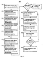
- the controller 108 determines a user uplink bandwidth metric.
- the controller 108 determines SUUB, the specific user uplink bandwidth.
- step 304 the controller tentatively divides the available uplinks between the gateway and the user terminals according to equations [2] and [3]:
- TentAssign g w u l Num up / ( 1 + SUUB )
- TentAssign gwul is the tentative gateway uplink assignment and TentAssign uul is the tentative user uplink assignment.
- equations [2] and [3] assign, in total, all the available uplinks either to the gateway or to the users, but that the assignments will not necessarily be whole numbers of uplinks. Such non-integer assignments are allowed if the uplinks may be shared between the users and gateways. Otherwise, the controller 108 adjusts the tentative assignments to whole numbers of uplinks.
- the tentative assignment of uplinks is an optimal allocation of uplinks in the sense that it maximizes the total traffic that the uplinks carry subject to the ratio R and the utilization efficiencies. Alternative assignments will carry less traffic. The further an alternate assignment varies from the tentative assignment, the less traffic that assignment carries.
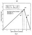
- Figure 4 that figure illustrates a graph 400 of assignments of uplinks to a gateway, and the resulting outbound capacity used in the outbound direction.
- the graph 400 reflects the fact that user terminal inbound traffic generates the responsive outbound traffic from the gateway. Therefore, when the user terminals have less than a certain amount of uplink bandwidth for inbound transmissions, the gateway outbound traffic according falls.
- the point 402 illustrates the tentative assignment.
- the controller 108 uses the actual traffic carried in the gateway uplinks as a measure of traffic carrying capacity of an assignment of UL gw uplinks to the gateways and UL u uplinks to the users. This measure is accurate because the traffic carried in the user uplinks is 1/R the traffic carried in the gateway uplinks.
- the controller determines CarriedUp for each of the assignments that result from equations [4A] and [4B] and then, at step 310, makes a final uplink assignment depending on which of the two assignments gives the greater capacity:
- the controller 108 proceeds to assign downlinks to the gateways and users.
- the controller 108 makes the assignments such that all the traffic offered to downlinks by the uplinks is carried to the ground. Such assignments may be achieved if the number of available downlinks and the utilization efficiencies of the downlinks are adequate. Otherwise, the controller 108 preferably delivers the greatest possible amount of traffic in the outbound and inbound directions. The controller 108 delivers this maximum using the approach outlined below.
- the controller determines the amount of traffic offered to the gateway downlinks and the user downlinks. This determination depends upon whether the satellite has a concentrating capability. In other words, the determination depends upon whether the satellite can discard unused uplink bandwidth before offering traffic to the downlinks.
- the traffic offered to a downlink is adjusted to reflect the fact that only part of the uplink carries useful data. The rest does not carry traffic and is discarded before downlinking.
- the traffic offered to a downlink, without concentration is exactly equal to traffic arriving in the corresponding uplink. None is discarded.
- the controller 108 (at step 318) preferably assigns ceiling (Need gwdl ) downlinks to the gateways and ceiling(Need udl ) downlinks to the users. Any additional downlinks may be held in reserve or assigned in any manner desired.
- the controller 108 preferably finds an assignment that maximizes the overall throughput of the system, even if the assignment falls short of delivering all of the uplinked traffic.
- the uplinked traffic will be reduced to match the maximal downlink capacity that results from the assignment.
- the controller 108 assigns each downlink exclusively to the gateways or the users. In further systems, there may be uplinks that are not concentrated and that are therefore downlinked in their entirety (or else are abandoned). The operation of the controller 108 in these systems is explained below.
- the controller 108 examines the traffic-carrying capacity of alternative downlink assignments where each assignment is a whole number of downlinks. The controller 108 proceeds by working backward through the preceding equations from the alternative assignment of downlinks to the capacity.
- the measure of capacity is preferably the CarriedUp value obtained using equation [5].
- the controller 108 considers alternative assignments of DL gw downlinks assigned to gateways and DL u downlinks assigned to user terminals (step 320). The controller 108 then preferably determines the capacity of the downlinks to carry traffic offered to them. Equations [7] and [8] may be modified to produce equivalent traffic offered, ETO equations shown below in equations [11] and [12]. The ETO is the amount of offered traffic that would fill the downlink assignment currently under consideration.
- ETO is measured in units equal to the capacity of an uplink.
- ETO g w d l DL g w ⁇ UE g w d l / RelSize
- ETO u d l DL u ⁇ UE u d l / RelSize
- uplinked traffic is carried down in indivisible quanta of full uplinks. Therefore, without concentration, the controller 108 compensates by truncating values of ETO to whole integers (step 322).
- one restriction assumed in the non-concentrated traffic case is that the quotient (UE/RelSize) is greater than or equal to 1, otherwise the uplink would not fit into a downlink. Note also that if traffic is concentrated, the restriction does not apply.
- either or both of the outbound and inbound paths can be concentrated or not concentrated independently of the other.
- the present technique applies to each case, however. For example, in a non-concentrated path, the value of ETO will be compensated by truncation, while in the concentrated path it will not be truncated).
- the controller 108 preferably converts ETO to equivalent uplinks, EUL at step 324.
- Equivalent uplinks are the number of uplinks which would offer ETO traffic to the downlinks when the uplink utilization efficiency is taken into account. Again, a distinction is preferably made between concentrating and non-concentrating directions through the satellite.
- EUL g w minimum ( Assign g w u l , ETO u d l / UE g w u l )
- EUL u minimum ( Assign u u l , ETO g w d l / UE u u l )
- Assign gwul and Assign uul are the uplink assignments obtained from equations [6A] or [6B]. They are included here since the satellite cannot downlink more traffic than is uplinked to it.
- EUL g w minimum ( Assign g w u l , ETO u d l )
- EUL u minimum ( Assign u u l , ETO g w d l ) and, again, traffic carried, TC, is determined using equation [15].
- the controller 108 preferably repeats this process for all possible downlink assignments.
- the assignment which obtains the greatest value for TC is selected (step 328).
- the assignment values are put into Assign gwdl and Assign udl for communication to the gateways and users, in a bandwidth assignment message.
- the capacity of the system, TC is equal to the uplink capacity. Measuring this capacity as the capacity of the gateway uplinks (i.e., using CarriedUp gwul ), the capacity is 5.6 links worth of traffic.
- the controller would assign Assign gwul , Assign uul, Assign gwdl , and Assign udl each equal to 5.
- the asymmetric assignment carries 40% more traffic than the symmetric assignment.
- the controller 108 is used during system planning, the system designers will be alerted to the fact that only 7 downlinks are required to support 10 uplinks. By incorporating the asymmetry into the design of the system, critical satellite resources which would have been wasted can instead be used to support other beams and to increase the useful capacity of the satellite.
- Figures 5 and 6 next present additional examples of asymmetric bandwidth assignment.
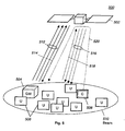
- a communication system 500 including a bent-pipe non-concentrating satellite 502, a gateway 504, and numerous user terminals 506.
- a controller 508 is also present in the spot beam 510 generated by the satellite 502.
- Figure 5 further illustrates three gateway uplinks 512, a gateway downlink 514, three user terminal downlinks 516, a user terminal uplink 518, and a signaling channel 520.
- the way in which the uplinks 512, 518 and downlinks 514, 516 were assigned is explained below.
- Table 3 Parameter Value R 10 U Euul 0.3 UE gwul 1 . 0 UE udl 1. 0 UE gwdl 1.0 RelSize 1 Num up 4 Mum down 4
- the capacity of the communication system 500, TC is equal to the uplink capacity, or 3 units of traffic (assuming each uplink carries one unit of traffic).
- the controller would assign Assign gwul , Assign uul , Assign gwd1 , and Assign udl each equal to 2.
- the asymmetric assignment carries 50% more traffic than the symmetric assignment.
- the satellite 302 provided the spot beam 310 with equal bandwidth in the uplinks 312, 318 and downlinks 314, 316. Although the total uplink and downlink bandwidth provided was balanced or equal, the controller 308 assigned it asymmetrically.
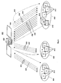
- Figure 6 illustrates application of the present method for assigning bandwidth in a more complicated communication system 600.
- Figure 6 illustrates a satellite 602 providing three spot beams (beam1 604, beam2 606, and beam3 608) of coverage for the communication system 600.
- Beam1 604 includes the user terminals 610
- beam2 606 includes the user terminals 612
- beam3 608 includes the user terminals 614, a controller 616, and a gateway and monitor 618.
- the satellite 602 carries a statistical multiplexer 620 (i.e., a concentrator).
- Figure 6 also illustrates a signaling channel 622 and numerous uplinks 626, 630, 634, and 636 and downlinks 624, 628, 632, and 638 (to be discussed in more detail below).
- Table 4 describes the parameters of the system shown in Figure 6: Table 4 Parameter Value R 10 UE uul 0.3 UE gwul 1.0 UE udl 1 . 0 UE gwdl 1.0 RelSize 1.5 Num up 9 NUm down 10
- the assignment illustrated in Figure 6 gives the communication system 600 a traffic capacity of 9 traffic units. Note also that the system designers do not need to include the circuitry for a tenth uplink (to match the 10 downlinks), because ten uplinks are not required for maximum throughput operation.
- a conventional assignment of bandwidth would result in 5 user uplinks and downlinks and 5 gateway uplinks and downlinks. It is very likely that each of beam1 604 and beam2 606 would have been assigned two user uplinks and downlinks, and beam3 608 would have been assigned one user uplink and downlink and four gateway uplinks and downlinks.
- the conventional system capacity would have been 5 traffic units.
- the bandwidth assignment distributed by the controller 616 increases system capacity by 80% in this example.
- the controller 616 creates an asymmetric provisioning of uplinks and downlinks.
- Beam1 604 and beam2 606 each are assigned three downlinks 624 (for user terminals 610), 628 (for user terminals 612) and one uplink 626 (for user terminals 610), 630 (for user terminals 612).
- beam3 608 three downlinks 632 and one uplink 634 are assigned to user terminals 614, while six uplinks 636 and one downlink 638 are assigned to the gateway 618.
- the asymmetric assignment greatly increases system capacity.
- the controller 700 includes input parameter determination circuitry 702, uplink and downlink assignment circuitry (assignment circuitry) 704, and communication circuitry 706.
- the controller 700 may receive input parameters from engineering or marketing inputs 708, or from a controller input 710.
- the controller 700 transmits uplink and downlink assignment information to gateway terminals and user terminals using the gateway output 712 and the user terminal output 714 (both of which, for example, may couple to a transmitter that sends information over a single signaling channel).
- the input parameter determination circuitry 702 directly accepts (from a marketing study, for example), or determines (from monitor 110 information) the parameters of interest in designing or operating a communication system.
- the input parameters preferably, correspond to those illustrated in Table 1.
- the assignment circuitry 704 determines, as described above, an assignment of uplinks and downlinks to the user terminals and the gateway terminals.
- the communication circuitry 706 creates an appropriate message (in any supported format) that relays the uplink and downlink assignments to the gateways and user terminals.
- the communication circuitry 706 may use, for example, a single signaling channel received by the user terminals and the gateways for this purpose.
- the controller 700 may be implemented using one or more general purpose CPUs, DSPs, or ASICs, or using discrete logic, either as a general programmed computer executing instructions from a memory, or as a hardware only implementation.
- the controller 700 may be used as both a planning tool and as an operational tool.
- the controller 700 may be used to determine the number of uplinks and downlink to be built into a communication system, determine the assignment of the uplinks and downlinks to gateways and user terminals, and determine (based on expectations of user take-up of service and on the planned locations of the gateways) the number of uplinks and downlinks to be placed in each satellite beam.
- the planning tool first stores given or predetermined input parameters, and may be used to determine the remaining parameters (e.g., Num down ) in view of the equations above.
- the controller 700 may be used to periodically (e.g., once per day, week, month, or year) allocate and reallocate uplinks and downlinks on a semi-permanent or dynamically changing basis in an existing communication system.
- controller 700 may be onboard the satellite or on the ground. If the controller 700 is on the ground, it may be co-located with other ground elements or located away from the ground elements with a suitable wire or wireless interconnection, whichever is preferable in the system design. As noted above, the controller 700 may also be used to determine, with multiple gateways and satellite beams, the distribution of uplinks and downlinks in the many beams rather than only determining the number of uplinks and downlinks assigned to gateways and users.
- the present invention assigns communication bandwidth based in part on the asymmetry in inbound and outbound communication between terminals through a satellite.
- the bandwidth assignments are tailored to the actual needs of the terminals in terms of both bandwidth and latency. As a result, the bandwidth assignments significantly increase the communication capacity, revenue, and throughput of the communication system.
Landscapes
- Engineering & Computer Science (AREA)
- Computing Systems (AREA)
- Physics & Mathematics (AREA)
- Astronomy & Astrophysics (AREA)
- Aviation & Aerospace Engineering (AREA)
- General Physics & Mathematics (AREA)
- Computer Networks & Wireless Communication (AREA)
- Signal Processing (AREA)
- Radio Relay Systems (AREA)
Claims (15)
- Procédé d'affectation de largeur de bande dans un système (100) de communication par satellite, le procédé comprenant les étapes consistant à :déterminer une affectation de liaison montante dans les liaisons montantes vers un satellite (102) à partir d'une passerelle (104) et une affectation de liaison montante dans les liaisons montantes vers le satellite (102) à partir des terminaux (106) d'utilisateur, les deux affectations montantes dans les liaisons montantes étant basées sur un rendement d'utilisation des liaisons montantes de passerelle, un rendement d'utilisation des liaisons montantes d'utilisateur, et un rapport entre les trafics sortant et entrant de la passerelle (104) ; etdéterminer une affectation de liaison descendante dans les liaisons descendantes vers les terminaux (106) d'utilisateur et la passerelle (104) depuis le satellite (102), basée sur le trafic offert aux terminaux (106) d'utilisateur et à la passerelle (104) en conformité avec l'affectation de liaison montante.
- Procédé selon la revendication 1, dans lequel l'étape consistant à déterminer une affectation de liaison montante comprend en outre la détermination d'une affectation non entière de liaison montante basée sur des sous-canaux formant une liaison montante.
- Procédé selon la revendication 1, dans lequel l'étape consistant à déterminer une affectation de liaison descendante comprend en outre la détermination d'une affectation de liaison descendante non entière basée sur des sous-canaux formant une liaison descendante.
- Procédé selon la revendication 1, dans lequel l'étape consistant à déterminer une affectation de liaison montante comprend en outre la détermination d'une affectation entière de liaison montante par évaluation d'affectations entières de liaisons montantes au voisinage d'une affectation non entière de liaisons montantes fournissant une capacité maximale de sortie.
- Procédé selon la revendication 4, dans lequel l'étape consistant à déterminer une affectation de liaison montante sélectionne le maximum de :

et
en conformité avec :




où TentAssigngwul est une affectation tentée de liaisons montantes à partir de la passerelle (104), Numup est un nombre total de liaisons montantes du système de communication, SUUB est une largeur de bande spécifique d'utilisateur, TentAssignuul est une affectation tentée de liaisons montantes à partir des terminaux (106) d'utilisateur, R est un rapport entre les trafics sortant et entrant, UEgwul est un rendement d'utilisation d'une liaison montante d'une passerelle, et UEuul est un rendement d'utilisation d'une liaison montante d'un terminal d'utilisateur. - Procédé selon la revendication 3, dans lequel l'étape consistant à déterminer une affectation de liaison montante comprend la détermination de :

et
en conformité avec :

et
où Assigngwul est une affectation de liaisons montantes à partir des passerelles (104), Numup est un nombre total de liaisons montantes du système de communication, SUUB est une largeur de bande spécifique d'utilisateur, TentAssignuul = est une affectation tentée de liaisons montantes à partir des terminaux (106) d'utilisateur, R est un rapport entre les trafics sortant et entrant, UEgwul est un rendement d'utilisation d'une liaison montante de passerelle, et UEuul est un rendement d'utilisation d'une liaison montante de terminal d'utilisateur. - Procédé selon la revendication 1, dans lequel l'étape consistant à déterminer une affectation de liaison descendante comprend en outre la détermination d'une affectation de liaison descendante basée en outre sur une capacité relative des liaisons montantes comparées aux liaisons descendantes.
- Procédé selon la revendication 7, dans lequel l'étape consistant à déterminer une affectation de liaison descendante comprend la détermination de :

et
où Needgwdl est un nombre de liaisons descendantes désirées pour chaque passerelle (104) et Needudl est un nombre de liaisons descendantes désirées pour les terminaux (106) d'utilisateur, RelSize est une taille relative de liaisons montantes comparées aux liaisons descendantes, TOgwdl est le trafic offert aux liaisons descendantes (116) de passerelle, TOudl est le trafic offert aux liaisons descendantes (120) de terminaux d'utilisateur, UEgwdl est un rendement d'utilisation d'une liaison descendante (116) de passerelle, et UEudl est un rendement d'utilisation d'une liaison descendante (120) de terminal d'utilisateur. - Dispositif de commande de largeur de bande de système de communication par satellite comprenant :un circuit d'affectation pouvant être mis en oeuvre pour déterminer au moins une affectation de liaison montante dans les liaisons montantes vers un satellite (102) à partir d'une passerelle (104) et une affectation de liaison montante des liaisons montantes vers le satellite (102) à partir des terminaux (106) d'utilisateur, l'au moins une affectation de liaison montante dans les liaisons montantes étant basée sur un rendement d'utilisation des liaisons montantes de passerelle, un rendement d'utilisation des liaisons montantes de terminal d'utilisateur, et un rapport entre les trafics de sortie et d'entrée de la passerelle (104) et une affectation de liaison descendante des liaisons descendantes vers les terminaux (106) d'utilisateur et la passerelle (104) à partir du satellite (102), en se basant sur le trafic offert aux terminaux d'utilisateurs et à la passerelle en conformité avec l'affectation de liaison montante ; etun circuit de communication destiné à communiquer l'affectation de liaison montante et l'affectation de liaison descendante aux terminaux (106) d'utilisateur et à la passerelle (104).
- Dispositif de commande de largeur de bande de système de communication par satellite selon la revendication 9, comprenant en outre un circuit de détermination de paramètres destiné à déterminer le rendement des liaisons montantes de passerelle, le rendement des liaisons montantes des terminaux d'utilisateur et le rapport des trafics.
- Système de communication par satellite comprenant :des terminaux (106) d'utilisateur ;une passerelle (104) ;un satellite (102) fournissant des liaisons montantes et des liaisons descendantes aux terminaux (106) d'utilisateur et à la passerelle (104) ; etun dispositif (108) de commande de largeur de bande comprenant un circuit d'affectation de liaison montante et de liaison descendante pouvant être mis en oeuvre pour déterminer une affectation de liaison montante dans les liaisons montantes vers le satellite (102) à partir d'une passerelle (104) et une affectation de liaison montante dans les liaisons montantes vers le satellite (102) à partir des terminaux (106) d'utilisateur, les deux affectations de liaison montante dans les liaisons montantes étant basées sur un rendement d'utilisation de la liaison montante de passerelle, un rendement d'utilisation de la liaison montante de terminal d'utilisateur et un rapport entre les trafics de sortie et d'entrée de la passerelle (104), et pouvant être mis en oeuvre pour déterminer une affectation de liaison descendante dans les liaisons descendantes vers les terminaux (106) d'utilisateur et la passerelle (104) à partir du satellite (102), en se basant sur le trafic offert aux terminaux (106) d'utilisateurs et à la passerelle (104) en conformité avec l'affectation de liaison montante.
- Système de communication par satellite selon la revendication 11, comprenant en outre un circuit de détermination de paramètres d'entrée destiné à déterminer le rendement des liaisons montantes de passerelle, le rendement des liaisons montantes des terminaux d'utilisateur et le rapport des trafics au moyen d'au moins l'une parmi l'évaluation de l'entrée du moniteur et la réception du rendement de la liaison montante de passerelle, du rendement de la liaison montante des terminaux d'utilisateur et du rapport des trafics comme entrées de conception.
- Système de communication par satellite selon la revendication 11, dans lequel les liaisons montantes sont divisibles en sous-canaux, et dans lequel le dispositif de commande de largeur de bande détermine des affectations non entières de liaison montante basées sur les sous-canaux.
- Système de communication par satellite selon la revendication 11, dans lequel les liaisons descendantes sont divisibles en sous-canaux, et dans lequel le dispositif de commande de largeur de bande détermine des affectations non entières de liaison descendante basées sur les sous-canaux.
- Système de communication par satellite selon la revendication 11, dans lequel le satellite comprend en outre un concentrateur, et dans lequel le dispositif de commande de largeur de bande détermine l'affectation de liaison descendante en conformité avec au moins l'un parmi un rendement de liaison descendante de terminal d'utilisateur et un rendement de liaison descendante de passerelle imposés par le concentrateur.
Applications Claiming Priority (2)
| Application Number | Priority Date | Filing Date | Title |
|---|---|---|---|
| US09/516,105 US6665518B1 (en) | 2000-03-01 | 2000-03-01 | Asymmetric assignment of space-borne communication system resources |
| US516105 | 2000-03-01 |
Publications (3)
| Publication Number | Publication Date |
|---|---|
| EP1130800A2 EP1130800A2 (fr) | 2001-09-05 |
| EP1130800A3 EP1130800A3 (fr) | 2004-03-03 |
| EP1130800B1 true EP1130800B1 (fr) | 2006-09-06 |
Family
ID=24054148
Family Applications (1)
| Application Number | Title | Priority Date | Filing Date |
|---|---|---|---|
| EP01103597A Expired - Lifetime EP1130800B1 (fr) | 2000-03-01 | 2001-02-21 | Allocation asymmétrique de ressources dans un système de communications satellitaires |
Country Status (4)
| Country | Link |
|---|---|
| US (2) | US6665518B1 (fr) |
| EP (1) | EP1130800B1 (fr) |
| JP (1) | JP2001267996A (fr) |
| DE (1) | DE60122806T2 (fr) |
Families Citing this family (27)
| Publication number | Priority date | Publication date | Assignee | Title |
|---|---|---|---|---|
| KR100358444B1 (ko) | 1999-07-27 | 2002-10-25 | 엘지전자 주식회사 | 휴대 무선 전화기의 안테나 매칭 장치 |
| JP2001308771A (ja) * | 2000-04-26 | 2001-11-02 | Mitsubishi Electric Corp | 衛星チャネル割当方法および衛星通信システムならびに衛星通信用地球局 |
| JP2002112326A (ja) * | 2000-10-02 | 2002-04-12 | Ntt Docomo Inc | 無線リソース割当方法及び基地局装置 |
| US6804492B2 (en) * | 2001-04-04 | 2004-10-12 | Hughes Electronics Corporation | High volume uplink in a broadband satellite communications system |
| US6904265B1 (en) * | 2001-04-11 | 2005-06-07 | Hughes Electronics Corporation | Capacity management in a broadband satellite communications system |
| KR20030033436A (ko) * | 2001-10-23 | 2003-05-01 | 엘지전자 주식회사 | 위성 통신망의 데이터 전송률 제어방법 |
| KR100884956B1 (ko) | 2002-08-14 | 2009-02-23 | 엘지전자 주식회사 | 비대칭 양방향 패킷데이터 송수신 방법 및 시스템 |
| JP4667364B2 (ja) | 2003-01-28 | 2011-04-13 | ザ・ボーイング・カンパニー | 衛星通信データのデジタル処理のためのシステムおよび方法 |
| US20060203724A1 (en) * | 2005-03-08 | 2006-09-14 | Donna Ghosh | Multi-carrier, multi-flow, reverse link medium access control for a communication system |
| JP4606249B2 (ja) * | 2005-05-18 | 2011-01-05 | 富士通株式会社 | 情報処理方法及びルータ |
| US9955438B2 (en) * | 2005-09-27 | 2018-04-24 | Qualcomm Incorporated | Method and apparatus for carrier allocation and management in multi-carrier communication systems |
| US8538323B2 (en) * | 2006-09-26 | 2013-09-17 | Viasat, Inc. | Satellite architecture |
| US20090295628A1 (en) * | 2006-09-26 | 2009-12-03 | Viasat, Inc. | Satellite System Optimization |
| US8107875B2 (en) * | 2006-09-26 | 2012-01-31 | Viasat, Inc. | Placement of gateways near service beams |
| EP2645597B2 (fr) | 2006-09-26 | 2024-03-06 | ViaSat, Inc. | Systèmes de satellites à faisceau étroit améliorés |
| US20090298423A1 (en) * | 2006-10-03 | 2009-12-03 | Viasat, Inc. | Piggy-Back Satellite Payload |
| EP2095543A1 (fr) * | 2006-12-01 | 2009-09-02 | Fox Interactive Media Labs | Procédés, systèmes et programmes informatiques pour assurer une identification de collision de liaison montante |
| US8152237B2 (en) * | 2009-05-13 | 2012-04-10 | Michigan Tube Swagers & Fabricators, Inc. | Stacking chair |
| US9184829B2 (en) | 2010-05-02 | 2015-11-10 | Viasat Inc. | Flexible capacity satellite communications system |
| US8144643B2 (en) | 2010-05-02 | 2012-03-27 | Viasat, Inc. | Flexible capacity satellite communications system with flexible allocation between forward and return capacity |
| US10511379B2 (en) | 2010-05-02 | 2019-12-17 | Viasat, Inc. | Flexible beamforming for satellite communications |
| US8660482B2 (en) * | 2010-10-14 | 2014-02-25 | Space Systems/Loral, Llc | Broadband satellite with dual frequency conversion and bandwidth aggregation |
| US9363009B2 (en) | 2012-01-16 | 2016-06-07 | The Boeing Company | Routing information through a blocking splitter-combiner network |
| WO2017023621A1 (fr) * | 2015-07-31 | 2017-02-09 | Viasat, Inc. | Constellation de satellites de capacité flexible |
| US11088757B2 (en) | 2017-03-16 | 2021-08-10 | Viasat, Inc. | High-throughput satellite with sparse fixed user beam coverage |
| SG11201907748VA (en) | 2017-04-10 | 2019-09-27 | Viasat Inc | Coverage area adjustment to adapt satellite communications |
| CN119136303A (zh) * | 2023-06-12 | 2024-12-13 | 大唐移动通信设备有限公司 | 一种信息处理方法、装置及可读存储介质 |
Family Cites Families (16)
| Publication number | Priority date | Publication date | Assignee | Title |
|---|---|---|---|---|
| US4425639A (en) * | 1981-01-12 | 1984-01-10 | Bell Telephone Laboratories, Incorporated | Satellite communications system with frequency channelized beams |
| US5539730A (en) * | 1994-01-11 | 1996-07-23 | Ericsson Ge Mobile Communications Inc. | TDMA/FDMA/CDMA hybrid radio access methods |
| FR2727590B1 (fr) * | 1994-11-24 | 1996-12-27 | Alcatel Espace | Charge utile de satellite a canaux transparents integres |
| US5594940A (en) * | 1994-12-22 | 1997-01-14 | Motorola, Inc. | Statistically robust traffic modeling method and apparatus |
| US6377561B1 (en) * | 1996-06-24 | 2002-04-23 | Spar Aerospace Limited | Data communication satellite system and method of carrying multi-media traffic |
| US6650868B1 (en) * | 1997-02-12 | 2003-11-18 | Ericsson, Inc. | Mobile satellite phone system incorporating symmetrical and non-symmetrical waveform modes |
| US6175719B1 (en) * | 1997-06-25 | 2001-01-16 | Hughes Electronics Corporation | Multi-spot-beam satellite system with broadcast and surge capacity capability |
| US6105060A (en) * | 1997-09-05 | 2000-08-15 | Worldspace, Inc. | System for providing global portable internet access using low earth orbit satellite and satellite direct radio broadcast system |
| US6101385A (en) * | 1997-10-09 | 2000-08-08 | Globalstar L.P. | Satellite communication service with non-congruent sub-beam coverage |
| US6016311A (en) * | 1997-11-19 | 2000-01-18 | Ensemble Communications, Inc. | Adaptive time division duplexing method and apparatus for dynamic bandwidth allocation within a wireless communication system |
| US6128469A (en) * | 1998-03-21 | 2000-10-03 | Aeroastro, Inc. | Satellite communication system with a sweeping high-gain antenna |
| US6366761B1 (en) * | 1998-10-06 | 2002-04-02 | Teledesic Llc | Priority-based bandwidth allocation and bandwidth-on-demand in a low-earth-orbit satellite data communication network |
| US6317420B1 (en) * | 1999-06-25 | 2001-11-13 | Qualcomm Inc. | Feeder link spatial multiplexing in a satellite communication system |
| US6650630B1 (en) * | 1999-06-25 | 2003-11-18 | Telefonaktiebolaget Lm Ericsson (Publ) | Resource management and traffic control in time-division-duplex communication systems |
| US6707798B1 (en) * | 2000-03-31 | 2004-03-16 | Ensemble Communications | Method and apparatus for reducing co-channel interference in a frame-synchronized wireless communication system |
| US20020003776A1 (en) * | 2000-04-28 | 2002-01-10 | Gokhale Dilip S. | Interworking unit for integrating terrestrial ATM switches with broadband satellite networks |
-
2000
- 2000-03-01 US US09/516,105 patent/US6665518B1/en not_active Expired - Lifetime
-
2001
- 2001-02-21 EP EP01103597A patent/EP1130800B1/fr not_active Expired - Lifetime
- 2001-02-21 DE DE60122806T patent/DE60122806T2/de not_active Expired - Fee Related
- 2001-02-28 JP JP2001055052A patent/JP2001267996A/ja active Pending
-
2003
- 2003-09-15 US US10/662,255 patent/US20040058646A1/en not_active Abandoned
Also Published As
| Publication number | Publication date |
|---|---|
| EP1130800A2 (fr) | 2001-09-05 |
| US6665518B1 (en) | 2003-12-16 |
| EP1130800A3 (fr) | 2004-03-03 |
| DE60122806D1 (de) | 2006-10-19 |
| DE60122806T2 (de) | 2006-12-28 |
| JP2001267996A (ja) | 2001-09-28 |
| US20040058646A1 (en) | 2004-03-25 |
Similar Documents
| Publication | Publication Date | Title |
|---|---|---|
| EP1130800B1 (fr) | Allocation asymmétrique de ressources dans un système de communications satellitaires | |
| US8311006B2 (en) | Resource fairness policies for allocation of resources in a satellite communications system | |
| US10020875B2 (en) | Dynamic bandwidth resource allocation for satellite downlinks | |
| US5699355A (en) | System and methods for integrated sharing of satellite access link bandwidth | |
| US8351383B2 (en) | Carrier group apportionment for a satellite communications system | |
| US8433332B2 (en) | Dynamic frequency assignment in a multi-beam system | |
| US6985455B1 (en) | Method and system for providing satellite bandwidth on demand using multi-level queuing | |
| US6842437B1 (en) | System for providing satellite bandwidth on demand employing uplink frame formatting for smoothing and mitigating jitter and dynamically changing numbers of contention and data channels | |
| EP1244229B1 (fr) | Allocation de bande variable dans un système de communications par satellite | |
| US7107050B2 (en) | Resource manager for a satellite telecommunication system | |
| US10405234B2 (en) | Load balancing of committed information rate service sessions on TDMA inroute channels | |
| US6078577A (en) | System and method for packet data communication | |
| US7835693B2 (en) | Providing service in a satellite communications system to disadvantaged terminals | |
| US7535929B2 (en) | System and method for token-based PPP fragment scheduling | |
| US6738363B1 (en) | Method and apparatus for scheduling call admission control in satellite and wireless networks | |
| MXPA00010831A (es) | Sistema para proporcionar ancho de banda de satelites sobre pedido empleando formato de cuadro de enlace ascendente para aplanar y mitigar fluctuaciones y numeros dinamicamente cambiantes de los canales de contencion y datos. | |
| Werner et al. | Multiservice traffic model and bandwidth demand for broadband satellite systems | |
| Acar et al. | Weighted fair bandwidth-on-demand (WFBoD) for geostationary satellite systems |
Legal Events
| Date | Code | Title | Description |
|---|---|---|---|
| PUAI | Public reference made under article 153(3) epc to a published international application that has entered the european phase |
Free format text: ORIGINAL CODE: 0009012 |
|
| AK | Designated contracting states |
Kind code of ref document: A2 Designated state(s): AT BE CH CY DE DK ES FI FR GB GR IE IT LI LU MC NL PT SE TR |
|
| AX | Request for extension of the european patent |
Free format text: AL;LT;LV;MK;RO;SI |
|
| RAP1 | Party data changed (applicant data changed or rights of an application transferred) |
Owner name: NORTHROP GRUMMAN CORPORATION |
|
| RAP1 | Party data changed (applicant data changed or rights of an application transferred) |
Owner name: NORTHROP GRUMMAN CORPORATION |
|
| PUAL | Search report despatched |
Free format text: ORIGINAL CODE: 0009013 |
|
| AK | Designated contracting states |
Kind code of ref document: A3 Designated state(s): AT BE CH CY DE DK ES FI FR GB GR IE IT LI LU MC NL PT SE TR |
|
| AX | Request for extension of the european patent |
Extension state: AL LT LV MK RO SI |
|
| 17P | Request for examination filed |
Effective date: 20040728 |
|
| AKX | Designation fees paid |
Designated state(s): DE FR GB IT |
|
| 17Q | First examination report despatched |
Effective date: 20041111 |
|
| GRAP | Despatch of communication of intention to grant a patent |
Free format text: ORIGINAL CODE: EPIDOSNIGR1 |
|
| GRAS | Grant fee paid |
Free format text: ORIGINAL CODE: EPIDOSNIGR3 |
|
| GRAA | (expected) grant |
Free format text: ORIGINAL CODE: 0009210 |
|
| AK | Designated contracting states |
Kind code of ref document: B1 Designated state(s): DE FR GB IT |
|
| PG25 | Lapsed in a contracting state [announced via postgrant information from national office to epo] |
Ref country code: IT Free format text: LAPSE BECAUSE OF FAILURE TO SUBMIT A TRANSLATION OF THE DESCRIPTION OR TO PAY THE FEE WITHIN THE PRESCRIBED TIME-LIMIT;WARNING: LAPSES OF ITALIAN PATENTS WITH EFFECTIVE DATE BEFORE 2007 MAY HAVE OCCURRED AT ANY TIME BEFORE 2007. THE CORRECT EFFECTIVE DATE MAY BE DIFFERENT FROM THE ONE RECORDED. Effective date: 20060906 |
|
| REG | Reference to a national code |
Ref country code: GB Ref legal event code: FG4D |
|
| REF | Corresponds to: |
Ref document number: 60122806 Country of ref document: DE Date of ref document: 20061019 Kind code of ref document: P |
|
| PGFP | Annual fee paid to national office [announced via postgrant information from national office to epo] |
Ref country code: DE Payment date: 20070330 Year of fee payment: 7 |
|
| EN | Fr: translation not filed | ||
| PLBE | No opposition filed within time limit |
Free format text: ORIGINAL CODE: 0009261 |
|
| STAA | Information on the status of an ep patent application or granted ep patent |
Free format text: STATUS: NO OPPOSITION FILED WITHIN TIME LIMIT |
|
| 26N | No opposition filed |
Effective date: 20070607 |
|
| GBPC | Gb: european patent ceased through non-payment of renewal fee |
Effective date: 20070221 |
|
| PGFP | Annual fee paid to national office [announced via postgrant information from national office to epo] |
Ref country code: IT Payment date: 20070517 Year of fee payment: 7 |
|
| PG25 | Lapsed in a contracting state [announced via postgrant information from national office to epo] |
Ref country code: GB Free format text: LAPSE BECAUSE OF NON-PAYMENT OF DUE FEES Effective date: 20070221 Ref country code: FR Free format text: LAPSE BECAUSE OF FAILURE TO SUBMIT A TRANSLATION OF THE DESCRIPTION OR TO PAY THE FEE WITHIN THE PRESCRIBED TIME-LIMIT Effective date: 20070511 |
|
| PG25 | Lapsed in a contracting state [announced via postgrant information from national office to epo] |
Ref country code: FR Free format text: LAPSE BECAUSE OF FAILURE TO SUBMIT A TRANSLATION OF THE DESCRIPTION OR TO PAY THE FEE WITHIN THE PRESCRIBED TIME-LIMIT Effective date: 20060906 |
|
| PG25 | Lapsed in a contracting state [announced via postgrant information from national office to epo] |
Ref country code: DE Free format text: LAPSE BECAUSE OF NON-PAYMENT OF DUE FEES Effective date: 20080902 |
|
| PG25 | Lapsed in a contracting state [announced via postgrant information from national office to epo] |
Ref country code: IT Free format text: LAPSE BECAUSE OF NON-PAYMENT OF DUE FEES Effective date: 20080221 |