EP1131109B1 - Verfahren und vorrichtung zur behandlung von verunreinigten abfällen - Google Patents
Verfahren und vorrichtung zur behandlung von verunreinigten abfällen Download PDFInfo
- Publication number
- EP1131109B1 EP1131109B1 EP99956059A EP99956059A EP1131109B1 EP 1131109 B1 EP1131109 B1 EP 1131109B1 EP 99956059 A EP99956059 A EP 99956059A EP 99956059 A EP99956059 A EP 99956059A EP 1131109 B1 EP1131109 B1 EP 1131109B1
- Authority
- EP
- European Patent Office
- Prior art keywords
- grinding
- waste
- chamber
- sterilisation
- heating
- Prior art date
- Legal status (The legal status is an assumption and is not a legal conclusion. Google has not performed a legal analysis and makes no representation as to the accuracy of the status listed.)
- Expired - Lifetime
Links
Images




Classifications
-
- B—PERFORMING OPERATIONS; TRANSPORTING
- B09—DISPOSAL OF SOLID WASTE; RECLAMATION OF CONTAMINATED SOIL
- B09B—DISPOSAL OF SOLID WASTE NOT OTHERWISE PROVIDED FOR
- B09B3/00—Destroying solid waste or transforming solid waste into something useful or harmless
- B09B3/30—Destroying solid waste or transforming solid waste into something useful or harmless involving mechanical treatment
- B09B3/35—Shredding, crushing or cutting
-
- A—HUMAN NECESSITIES
- A61—MEDICAL OR VETERINARY SCIENCE; HYGIENE
- A61L—METHODS OR APPARATUS FOR STERILISING MATERIALS OR OBJECTS IN GENERAL; DISINFECTION, STERILISATION OR DEODORISATION OF AIR; CHEMICAL ASPECTS OF BANDAGES, DRESSINGS, ABSORBENT PADS OR SURGICAL ARTICLES; MATERIALS FOR BANDAGES, DRESSINGS, ABSORBENT PADS OR SURGICAL ARTICLES
- A61L11/00—Methods specially adapted for refuse
-
- B—PERFORMING OPERATIONS; TRANSPORTING
- B02—CRUSHING, PULVERISING, OR DISINTEGRATING; PREPARATORY TREATMENT OF GRAIN FOR MILLING
- B02C—CRUSHING, PULVERISING, OR DISINTEGRATING IN GENERAL; MILLING GRAIN
- B02C19/00—Other disintegrating devices or methods
- B02C19/0056—Other disintegrating devices or methods specially adapted for specific materials not otherwise provided for
- B02C19/0075—Other disintegrating devices or methods specially adapted for specific materials not otherwise provided for specially adapted for disintegrating medical waste
-
- B—PERFORMING OPERATIONS; TRANSPORTING
- B09—DISPOSAL OF SOLID WASTE; RECLAMATION OF CONTAMINATED SOIL
- B09B—DISPOSAL OF SOLID WASTE NOT OTHERWISE PROVIDED FOR
- B09B2101/00—Type of solid waste
- B09B2101/65—Medical waste
Definitions
- the invention relates to the treatment of contaminated waste such as hospital waste to transform it into ordinary dry waste not contaminated.
- contaminated waste such as hospital waste
- the term "contaminated” and its derivatives traditionally refer only to pollution of biological origin (pathogenic germs, viruses, microorganisms, contagions ).
- Contaminated waste such as hospital waste can be very varied in nature: they can be metallic objects (needles, syringes, ancillaries, prostheses, ...), and / or made of synthetic materials (syringes, bags, packaging, dressings, ...), and / or in fibrous materials (fabrics, cotton, %) and / or fluids (blood, %) and / or pharmaceutical compositions or cleaning .... This variety considerably complicates the problem of their treatment of transformation into ordinary dry waste.
- Pressurized steam heating processes consist of placing the waste in an autoclave in the presence of a pressure of water vapor after possible successive evacuations. These processes have been the preferred route to date insofar as steam of pressurized water makes it possible to sterilize waste quickly (of the order of 15 mins), at relatively low temperature (around 125 ° C), and take advantage of advantages of the presence of water vapor in the reaction medium (effect catalyst for certain chemical reactions, homogenization of temperature at within the reaction medium, thermal transfer improved by the condensation of the water vapour).
- these methods require an expensive installation. (autoclave).
- the loading / pressurization and cooling / emptying are long and affect productivity and energy consumption.
- the waste thus treated is gorged humidity and are later more difficult, and therefore more expensive, to incinerate, and / or present the risk of being able to produce polluting flows.
- the invention therefore aims to overcome these drawbacks by proposing a method and an apparatus making it possible to carry out the processing of economically contaminated waste such as hospital waste (in investments and / or user costs), while ensuring sterilization completes the waste in a short treatment time - in particular of the order of or less than 15min-.
- the invention also aims to propose a method and an apparatus particularly safe and avoiding accidental contamination of users and personnel performing maintenance or repair operations.
- the invention also aims to allow easy maintenance or repair operations. repair in case of breakdown.
- the invention also aims to propose a simple device, compact, robust, and very reliable in operation.
- the invention also aims to propose a method and an apparatus treatment emitting only few residual gases and in which the gases emitted are treated before being released into the atmosphere, in particular to avoid pollution and bad smells.
- the invention thus aims in particular to propose an apparatus which can independently handle waste processing from a simple electric power supply.
- the invention thus aims to propose a method and an apparatus can be implemented simply on a waste production site -especially in hospitals-.
- the invention relates to a treatment method contaminated waste such as hospital waste in which the waste in a grinding / sterilization chamber defining a closed enclosure within which the waste is crushed and sterilized by heating, characterized in that the waste is circulated in the grinding / sterilization in several grinding / sterilization cycles by means of grinding.
- the waste is crushed several times and are sterilized by heating in the chamber grinding / sterilization.
- the invention extends to a processing apparatus for placing implementing a method according to the invention.
- the invention thus relates to an apparatus for processing contaminated waste such as hospital waste, including a grinding / sterilization adapted to be able to define a closed enclosure containing waste shredding means and heating means suitable for ability to heat waste to sterilize it, characterized in that the grinding / sterilization chamber includes means for conveying adapted to be able to circulate the waste in several cycles of grinding through the grinding means.
- the invention makes it possible to treat waste contaminated with simple, fast, safe and economical.
- the apparatus according to the invention is compact and inexpensive to invest and use and can be installed on the actual waste production site. Its operation is autonomous and it does not require any adjustment or monitoring intervention, except, the if necessary, periodic purging of residual liquids from the treatment center gases (this purging is even avoided if the gases are treated by post-combustion catalytic under the effect of intense heating).
- the waste is sterilized and crushed in a short time (conventionally around 15 min as in previous treatments with pressurized steam, while the treatments previous dry heat require a duration of the order of double for the sterilization), without any residual contamination.
- Waste is free of residual moisture after treatment and can be easily incinerated or deposited in a center landfill or landfill, like simple household garbage.
- there is no risk of contamination since the whole grinding / sterilization chamber can be sterilized before intervention.
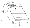
- the device for treating contaminated waste according to the invention is in the general form of a box parallelepiped defined by a structure of metal beams forming a frame 1 rigid, and of peripheral external walls 2, preferably metallic, which can be fitted on the inside with thermal insulation.
- the walls external 2 are removable or can be opened to access the interior of the device.
- the apparatus comprises an inlet opening 3 for the waste to treat, with a hatch 4 articulated around a horizontal axis and controlled by a jack 5 between an open position and a closed position.
- a tilted pan 6 facilitates the introduction of waste and its feeding into chamber 7 of grinding / sterilization.
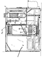
- Entrance opening 3 gives access to a first inlet chamber 8 which is separated from the grinding / sterilization chamber 7 by a vertical wall 9, provided with a flap 10 tilting by pivoting around a horizontal axis 11 under the effect of a jack 12.
- the hatch 10 can be placed either in the open position where it extends the inclined pan 6 downwards, a opening 13 being left free in the wall 9 for the introduction of waste in the grinding / sterilization chamber 7, either in the closed position where it closes this.
- the inclined pan 6 can, in variant not shown, be omitted. Indeed, it cannot be excluded that this pan inclined 6 is contaminated by contact with certain types of non-waterproof bags. The waste bags are then placed directly on the upper side of the hatch 10 which is then subjected to heating in chamber 7 of grinding / sterilization and is therefore also sterilized.
- the grinding / sterilization chamber 7 is separated from a cooling chamber 14, opposite the inlet chamber 8, by a wall vertical 15 in which is formed an opening 16 closed by a hatch 17 for waste disposal, pivotally mounted about a horizontal axis 18 and controlled by an actuator 19, so as to tilt on the inside of the chamber 7 grinding / sterilization.
- the cooling chamber 14 is delimited, opposite of the wall 15 which separates it from the grinding / sterilization chamber 7, by a vertical external wall 2 of the device, in which an outlet opening 20 treated waste is provided, this outlet opening 20 being closed by a hatch 21 articulated around a horizontal axis controlled by a jack 22.
- the cooling chamber 14 also includes a plate 23 mounted pivoting about a horizontal axis 24 and controlled by a cylinder 25, so that it can be placed either against a horizontal bottom 26 of the cooling chamber 14, under the opening 16 of the wall 15, to recover the waste from the grinding / sterilization chamber 7, ie in a position waste ejection in which this plate 23 is raised until it is inclined or even vertical against the external wall 2, so as to cause the waste to fall through the outlet opening 20 in a recovery bag 27 fixed on a bag holder 28 fixedly mounted under the outlet opening 20.
- the grinding / sterilization chamber 7 is also delimited by a front vertical wall 46 which can be a portion of external wall 2, by a rear vertical wall 47 which may be a portion of external wall 2, by a upper ceiling 29 hermetically closing the vertical walls 9, 15, 46, 47, and by a lower bottom 32 hermetically connecting the lower parts of these vertical walls 9, 15, 46, 47.
- a gas evacuation pipe 30 opens out top of the grinding / sterilization chamber 7.
- a solenoid valve 31 allows to open or close this gas evacuation pipe 30.
- a fan or compressor 59 placed on this pipe 30 makes it possible to extract the gases from the chamber 7 for grinding / sterilization.
- a pipe 33 opens into the bottom 32 by via a non-return valve 34 for supplying water and / or water vapor in the grinding / sterilization chamber 7 in the event of a breakdown.
- the walls 9, 15, 46; 47 of room 7 of grinding / sterilization define, when the doors 10, 17 are closed, a hermetically sealed enclosure, except for the solenoid valve 31 by which the process gases can be vented.
- the grinding treatment and waste sterilization is carried out in this enclosure.
- the grinding / sterilization chamber 7 contains a mat endless conveyor 35 with buckets 36, guided by angle deflection rollers 37, at least one of which is coupled to a motor 38.
- the rollers 37 are arranged so that the belt 35 runs opposite the internal face of each of the walls 46, 47, 29, 32, the buckets 36 being oriented inward.
- the carpet thus defines an endless loop along the walls 46, 47, 29, 32, of the chamber 7 of grinding / sterilization.
- chamber 7 includes a crusher 39 arranged in the lower part and adapted to receive the waste at grind from above, the crushed waste being released downwards.
- the grinder 39 comprises a plurality of rotary grinding shafts 40 driven in rotation by an engine group 41.
- the engine 38 driving the belt 35 and the engine group 41 of the crusher 39 are arranged outside the grinding / sterilization chamber 7, so as not to undergo the high temperatures which prevail there during the processing, and are connected to the idler rollers 37, respectively to the crusher 39, through one of the walls of the grinding / sterilization chamber 7, which, in the example shown, is the vertical side wall 9 of separation with the inlet chamber 8.
- the connection between the motor 38 and the corresponding roller 37 is adapted to be hermetic, that is to say waterproof gases and liquids.
- the connection between the power unit 41 and the grinder 39 at the passage of the wall 9 is adapted to be also airtight.
- the conveyor belt 35 can, in a variant not shown, be replaced by suitable means to create and maintain a draft pulsed at high speed circulating under the mill 39, then from bottom to top in a vertical side chimney through which the waste goes back up into room 7. At the exit of this chimney, the waste falls back into room 7 while passing opposite heating means up to the entrance to the mill 39.
- These means forming a pulsed air stream can be formed from one or more nozzle (s) powered by a high-speed fan placed in chamber 7, the effect suction and drive possibly being reinforced by a device Venturi.
- the different cylinders 5, 12, 19, 22, 25, 87 can be pneumatic or electropneumatic cylinders supplied with compressed air from an electric air compressor incorporated into the device.
- the cylinders can be replaced by all other actuators, for example motors electric. They are placed outside the broaching / sterilization chamber 7 which does not contain any temperature-sensitive motor or actuator.
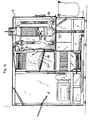
- a member 86 for supporting the waste on the grinder 39 is designed to exert pressure on the waste bag introduced in the grinding / sterilization chamber 7 and forcing it to pass through the grinder 39.
- the support member 86 may also have the function of breaking or deforming the waste whose shape would hinder its passage through the crusher 39, such as bottles, atomizers, ...
- This support member 86 is articulated in the chamber 7 so that it can be returned to the inactive position in which it does not does not interfere with the reintroduction of waste into the crusher 39.
- the support member 86 can be formed by a plate, a grid, one or more arms, ...
- this support member 86 is disposed under the hatch 17 waste disposal, articulated around the same horizontal axis 18, and controlled by a cylinder 87 disposed outside of chamber 7, the rod of which actuator is connected to a fastener secured to the through support member 86 a light provided in the evacuation hatch 17.
- the member 86 support is shown in the active position where it forces a bag of waste to pass to the across the mill 39.
- the support member 86 is shown in inactive position recalled against the evacuation hatch 17, for example by a spring (not shown) integrated in the axis 18 of articulation common to the hatch 17 and to the support member 86, the cylinder 87 being a single-acting cylinder.
- the mat 35 defines: a lower section 42 extending horizontally under the outlet of the crusher 39, the buckets 36 being oriented towards the high to recover the crushed waste falling from the crusher 39; a side section up 43, extending vertically along the front wall 46 and passing in a heating tunnel 48 fixed to this front wall 46; an upper section 44 extending horizontally above the mill 39, the buckets 36 being oriented downwards, i.e. towards the crusher 39 to unload there again waste; and a descending lateral section 45 extending vertically along from the rear wall 47 of the chamber 7 downwards, from the upper section 44 up to the lower section 42.
- the descending lateral section 45 also passes opposite a heating tunnel 49.
- the heating tunnels 48, 49 constitute means of dry heating, which are arranged in the chamber 7 higher than the grinder 39.
- Each heating tunnel 48, 49 is adapted to heat the waste contained in the troughs 36 and / or these troughs 36 and the mat 35 themselves by radiation and / or by convection, at a temperature suitable to allow sterilization garbage and carpet.
- the two tunnels 48, 49 are advantageously adapted to maintain in chamber 7 a temperature at least substantially homogeneous between 180 ° C and 220 ° C -in particular of the order of 200 ° C-, suitable to sterilize the entire grinding / sterilization chamber 7 and the elements it contains.
- Other tunnels of heating can be provided in room 7, for example a tunnel heating under the lower section 42 carried by the bottom 32.
- Each heating tunnel 48, 49 carries resistors electric 50, 51 extending opposite, on the inside, of the carpet 35 and its troughs 36.
- the electrical resistors 50, 51 are carried by a vertical metal wall 52, respectively 53, fixed to the front wall 46 or rear 47 of chamber 7.
- the electrical resistances are arranged on one face of this wall 52, 53 oriented towards the buckets 36, so that the heating thus produced is at least partly a heating by radiation.
- the heating tunnel 48 of the front wall 46 thus allows to sterilize the waste contained in the buckets 36 of the upward lateral section 43, that is to say the waste from the crusher 39. This waste is then recycled at the entrance to the mill 39 when they reach the upper section 44. It it should be noted that the upper section 44 being in the upper part of the chamber 7 then that the crusher 39 is in the lower part, the waste falls by gravity on a certain height, which has the effect of brewing them and improving the effect of the sterilization by better homogenization and temperature penetration within the waste.
- the heating tunnel 49 of the descending lateral section 45 has the effect of sterilizing the carpet 35 and the buckets 36 before they recover new waste possibly still contaminated.
- the mill 39 can be a traditional type mill, except that it is suitable for operating at temperature nominal operation of grinding / sterilization chamber 7 (included between 180 ° C and 220 ° C, especially around 200 ° C). To do this, just for example choosing to mount the grinding shafts 40 with sufficient play to account for thermal expansion, and to use a material resistant to this temperature. It should also be noted that the mill 39 being incorporated in inside the grinding / sterilization chamber 7, and the waste being crushed according to several successive grinding cycles, the grinder 39 can have a relatively coarse elementary grinding fineness for each pass of grinding. Thus, a relatively large clearance can be allowed between the different grinding knives.
- This game not only allows the consideration of thermal expansion, but also avoids blocking of the mill 39 and the mechanical incidents due to the passage of relatively hard metallic objects through the grinder 39.
- a grinder 39 having at least one pair of grinding shafts 40, to obtain a size average of the shredded waste, after several shredding cycles, less than 10 mm, in particular of the order of 2 mm to 5 mm.
- the mill 39 being integrated within the grinding / sterilization chamber 7 is itself subjected to the heating of permanent sterilization. More precisely, all parts of the mill 39 intended to be in contact with the waste (in particular the rotors) are disposed in the grinding / sterilization chamber 7, so that these parts are subjected to sterilization. Maintenance or repair operations on this shredder 39 are therefore without risk of contamination.
- a safety valve 54 is advantageously provided in the upper part of a wall of the chamber 7 to prevent any untimely increase in the pressure in this chamber 7 to a predetermined value, for example of the order of 1 to 2 bars (1 to 2.10 5 Pa).
- This valve 54 is disposed on the side of the cooling chamber 14, on the vertical side wall 15, and connected by a pipe to the pipe 30 for discharging the gases, downstream of the solenoid valve 31.
- chamber 7 is hermetically sealed for the treatment eliminates gaseous emissions outside the device.
- the solenoid valve 31 is open, and the chamber 7 is maintained crushing / sterilization in slight depression thanks to extraction and evacuation permanent throttle through the fan 59.
- the waste evacuation hatch 17 crushed rocks in the open position so as to extend under the upper section 44 of the conveyor belt 35, inside the loop formed by this belt 35. From the so the crushed waste that falls from the upper section 44 is captured by the evacuation hatch 17 on their way down.
- the evacuation pipe 30 belongs to a circuit treatment gas discharge including a gas treatment station 55 before they are released to the atmosphere.
- This gas treatment station 55 is in good shape general of vertical column and can be arranged inside the chamber 14 while being generally isolated from the atmosphere of the chamber 14 cooling to prevent any untimely leakage of gas from the gas evacuation circuit to the internal atmosphere of the cooling.
- thermal insulation is advantageously provided around the parts of the gas discharge circuit in contact with the atmosphere of the cooling chamber 14 (line 30, station 55, ).
- Cooling outside fresh air inlets 70 are provided in at least one wall 2 delimiting the cooling chamber 14, preferably in the form of non-return valves preventing the escape of air by these inlets 70.
- the discharge pipe 30 is provided with at least one mouth 71 air extraction by which the air from the cooling chamber 14 is exhausted in the evacuation circuit, via the treatment station 55.
- the mouth 71 extraction is preferably placed upstream of the fan or compressor 59 and can be formed by a non-return valve preventing any return of gas from the line 30 in the cooling chamber 14.
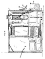
- the gas treatment station 55 comprises, in the mode shown in Figure 2, an upper area 56 filled with materials adsorbents, a lower zone 57 comprising a solution of slaked lime, and an inlet for the gases to be treated 58 between the upper zone 56 and the lower zone 57.
- This inlet 58 is the end of the evacuation pipe 30.
- the fan or compressor 59 in line 30 allows the gases to be sucked in and extracted from the grinding / sterilization chamber 7 to the gas treatment station 55.
- the gas treatment station 55 includes at its upper open end also a fan or compressor 60 which blows the gases treated in the atmosphere, through a chimney flue external to the device.
- the lower zone 57 makes it possible to treat the heavy gases which are recovered after treatment by a pipe 61 connecting the lower part of the lower area 57 at the top of the treatment center 55 above the area upper 56 upstream of the fan or compressor 60.
- At least one valve check valve 62 is provided in line 61.
- the lower part of station 55 of gas treatment includes an outlet for discharging liquid effluents into a drain pipe 63 provided with one or more valves 64.
- a drain pipe 65 is also provided in part lower of the grinding / sterilization chamber 7 to drain this chamber 7 as required.
- This drain pipe 65 is fitted with a valve drain 66.
- the pipe 33 for supplying water to the chamber 7 of grinding / sterilization in the event of a breakdown is connected to a pressurized water source 67 which is for example formed by a water reserve and an electric pump, or of a simple pressurized water supply from the running water network.
- a pressurized water source 67 which is for example formed by a water reserve and an electric pump, or of a simple pressurized water supply from the running water network.
- Resistance emergency power supply (not shown) with electric power supply advantageously provided at the bottom 32 of the grinding / sterilization chamber 7 for increase the evaporation of water in the event of a breakdown in the heating tunnels 48, 49 or more generally in case the temperature is not sufficient. We can then proceed, on the one hand, to the drainage of the residual water via line 65 of draining, on the other hand, to repair intervention.
- the apparatus further includes a controller 68 which is programmed to automate all or part of the device's operation.
- This PLC 68 can be programmed to control the operation of the shredder 39 and / or carpet 35 and / or heating tunnels 48, 49 and / or different solenoid valves and / or fans or compressors 59, 60 and / or different actuators for actuating the hatches and / or the source 67 of pressurized water ...
- the treatment process implemented in such an apparatus may be the following.
- the device is connected to the electrical network and powered up, and, if necessary, to the running water network.
- the entry hatches 4, 10 open.
- the tray 23 of the cooling chamber 14 recovering the waste is placed horizontally against the bottom 26 of the cooling chamber 14.
- the heating tunnels 48, 49 are supplied with electricity to be active in permanently and the grinder 39 is put into permanent operation, the rotors 40 being driven in permanent rotation.
- a sensor 69 placed under this hatch 10.
- the endless conveyor belt 35 is then put into permanent operation at constant speed.
- the cooling of the ground waste present on the plate 23 takes place for a predetermined period corresponding to a PLC 68 programmed time delay.
- the outlet hatch 21 is open, and tray 23 is tilted upwards so as to dispose of the crushed, sterilized and cooled waste in an outlet bag 27.
- the bag holder device 28 is advantageously provided with weighing means, means for welding the opening of the bag 27 of recovery of treated waste, and means 85 of printing a label allowing to identify in particular the origin of the waste, the parameters (temperature, duration %), the date and time of the treatment, all these means being known in themselves.
- These printing means 85 are for example placed on the front face of the device and controlled by the automaton 68 comprising a clock. which provides the date, time and duration of the treatment.
- At least one probe temperature placed in the grinding / sterilization chamber 7 provides the processing temperature.
- the label is printed when the machine 68 triggers the opening of the outlet hatch 21.
- the tests show that the waste of various kinds can be treated, sterilized and ground and cooled in an average time of around 15 min in a device according to the invention.
- the energy consumption according to the invention is not excessive and the treatment carried out is not polluting.
- the only releases are treated gases which do not are not polluting, and any liquid effluents from the treatment of heavy gases which are very low in volume, or even nonexistent in the variant described below.
- FIG. 6 represents an alternative embodiment of the heating means of the grinding / sterilization chamber 7 and of the station 55 treatment.
- the gases evacuated from the chamber 7 by the pipe 30 are treated by station 55 at high temperature (conventionally of the order of 500 to 700 ° C). They thus undergo catalytic combustion which has the effect of destroy by combustion any organic pollutants they contain.
- the processing station 55 is then formed of a column containing a plurality of concentric cylinders 76 assembled together so as to to form baffles for the circulation of gases until they emerge through the inside of the outlet cylinder 77 of smaller diameter.
- One of the cylinders internal 76 carries electrical resistors 75 which heat the air arriving via entry 74, at the desired temperature. The whole is surrounded by thermal insulation 78.
- this treatment station 55 can itself be incorporated in the grinding / sterilization chamber 7, especially in the upper part, to allow the recovery of calories from it issues.
- the grinding / sterilization chamber 7 includes elsewhere heat exchangers 79, 80, 81 inside which the gases hot from the treatment station 55 are brought through a pipe 82.
- the different exchangers 79, 80, 81 are connected to each other, and the last exchanger 81 has its output connected to an exhaust fan 83 which rejects the gases clean in the atmosphere.
- the heat exchangers 79, 80, 81 are exchangers with a separate gas circuit, the gases circulating in these exchangers do not mix not with the atmosphere inside the grinding / sterilization chamber 7. All form of heat exchanger with separate gas circuit can be used (coil, tubular or plate exchanger ).
- the heat exchangers 79, 80, 81 can be provided at the place of the heating tunnels 48, 49 of the first variant, or in combination with these tunnels.
- the air is permanently extracted of the grinding / sterilization chamber 7 via line 30, the solenoid valve 31 being open for the duration of the treatment.
- This extraction is performed by fan 83.
- Another fan or compressor can be provided on the line 30 as in the previous variant and / or on line 82 between the treatment station 55 and the heat exchangers 79, 80, 81.
- an apparatus has the following characteristics: overall dimensions: length between 2m and 2.5m; height between 1.5m and 2m; width between 0.5m and 1m; linear speed of movement of the belt 35: from 4 to 8 m / min; number of cycles of grinding: from 5 to 20; average electrical power consumed: from 20 to 80 kW; treatment capacity: 30 to 60 kg / h.
- the invention can be the subject of various other variants compared to the embodiments described.
Landscapes
- Engineering & Computer Science (AREA)
- Environmental & Geological Engineering (AREA)
- Health & Medical Sciences (AREA)
- General Health & Medical Sciences (AREA)
- Life Sciences & Earth Sciences (AREA)
- Animal Behavior & Ethology (AREA)
- Epidemiology (AREA)
- Public Health (AREA)
- Veterinary Medicine (AREA)
- Food Science & Technology (AREA)
- Processing Of Solid Wastes (AREA)
- Apparatus For Disinfection Or Sterilisation (AREA)
- Disintegrating Or Milling (AREA)
- Excavating Of Shafts Or Tunnels (AREA)
Claims (36)
- Verfahren zur Behandlung von verunreinigten Abfällen, wie zum Beispiel Krankenhausabfälle, bei dem man die Abfälle in einer Zerkleinerungs-/Sterilisationskammer (7) behandelt, die eine geschlossene Einfassung definiert, innerhalb derer man die Abfälle zerkleinert und man sie durch Erhitzen sterilisiert, dadurch gekennzeichnet, dass man die Abfälle in der Zerkleinerungs/Sterilisationskammer (7) in mehreren Zerkleinerungs- / Sterilisationszyklen durch Zerkleinerungsmittel (39) umlaufen lässt.
- Verfahren gemäß Anspruch 1, dadurch gekennzeichnet, dass man bei jedem Zerkleinerungszyklus die Abfälle einem Erhitzen in der Zerkleinerungs-/Sterilisationskammer (7) oberhalb und/oder unterhalb und/oder innerhalb der Zerkleinerungsmittel (39) aussetzt.
- Verfahren gemäß einem der Ansprüche 1 und 2, dadurch gekennzeichnet, das man die Abfälle durch trockenes Erhitzen - insbesondere durch einen Durchgang gegenüber von elektrischen Heizmitteln (48, 49) und/oder gegenüber von wenigstens einem Wärmeaustauscher (79, 80, 81) sterilisiert.
- Verfahren gemäß einem der Ansprüche 1 bis 3, dadurch gekennzeichnet, dass man die Abfälle im Durchlaufverfahren in aufeinander folgenden Zyklen ohne Unterbrechung durch die permanent angetriebenen und gegenüber den permanent aktiv gehaltenen Erhitzungsmitteln (48, 49, 79, 80, 81) liegenden Zerkleinerungsmittel (39) durchlaufen lässt.
- Verfahren gemäß einem der Ansprüche 1 bis 4, dadurch gekennzeichnet, dass man die Abfälle durch Auffangen am Ausgang der Zerkleinerungsmittel (39) auf in die Zerkleinerungs-/Sterilisationskammer (7) integrierte und zum Wiedereinführen der am Ausgang aufgefangenen Abfälle am Eingang der Zerkleinerungsmittel (39) angepasste Endlos-Beförderungsmitteln (35) durchlaufen lässt.
- Verfahren gemäß einem der Ansprüche 1 bis 5, dadurch gekennzeichnet, dass man zum Erhitzen der Abfälle das Innere der Zerkleinerungs-/Sterilisationskammer (7) einer Temperatur aussetzt, die zum Sterilisieren der sich dort befindlichen Abfälle geeignet ist, man die Abfälle während einer für die Gewährleistung ihrer vollständigen Sterilisation angepassten Zeitdauer in der Zerkleinerungs/Sterilisationskammer (7) behält, dass man sie anschließend in eine separate Kühlkammer (14) transferiert, und dass man ohne Unterbrechung der Zerkleinerungsmittel (39) noch der Erhitzungsmittel (48, 49, 79, 80, 81) neue Abfälle in die Zerkleinerungs-/Sterilisationskammer (7) einführt.
- Verfahren gemäß einem der Ansprüche 1 bis 6, dadurch gekennzeichnet, dass man die Behandlungsgase vor ihrer Abgabe in die Atmosphäre an einen Behandlungsposten (55) der Gase austrägt.
- Verfahren gemäß Anspruch 7, dadurch gekennzeichnet, dass man die Gase im Behandlungsposten (55) der Gase erhitzt, um ihre katalytische Verbrennung durchzuführen.
- Verfahren gemäß Anspruch 7 oder 8, dadurch gekennzeichnet, dass man die Behandlungsgase außerhalb der Zerkleinerungs-/Sterilisationskammer (7) während der gesamten Dauer der Behandlung permanent austrägt und dass man die heißen Gase nach ihrer Behandlung in wenigstens einem Wärmeaustauscher (79, 80, 81) mit separatem, in der Zerkleinerungs-/Sterilisationskammer (7) angeordnetem Gaskreislauf wiederaufbereitet.
- Verfahren gemäß einem der Ansprüche 1 bis 9, dadurch gekennzeichnet, dass man die Zerkleinerungs/Sterilisationskammer (7) wenigstens während der gesamten Dauer der Behandlung deutlich hermetisch geschlossen hält, ausgenommen eventuell den Austrag der Behandlungsgase.
- Verfahren gemäß einem der Ansprüche 7 bis 10, dadurch gekennzeichnet, dass man den Austrag der Gase während des Transfers der Abfälle zur Kühlkammer (14) und während einer zusätzlichen Dauer aufrecht erhält, die angepasst ist, um den Austrag der gesamten Gase vor der Einführung neuer in der Zerkleinerungs-/Sterilisationskammer (7) zu behandelnder Abfälle zu gewährleisten.
- Verfahren gemäß einem der Ansprüche 5 und Anspruch 1 bis 10, dadurch gekennzeichnet, dass man bei einem Ausfall der Zerkleinerungsmittel (39) und/oder der Erhitzungsmittel (48, 49, 79, 80, 81) und/oder der Beförderungsmittel (35) in die Zerkleinerungs/Sterilisationskammer (7) eine Wassermenge einführt, die durch Erhitzen in der Zerkleinerungs-/Sterilisationskammer (7) verdampft wird, und/oder eine Menge Wasserdampf, wobei diese Menge zur Sterilisation der gesamten Abfälle und anderer in der Zerkleinerungs-/Sterilisationskammer (7) vorhandener Elemente geeignet ist.
- Verfahren gemäß einem der Ansprüche 1 bis 12, dadurch gekennzeichnet, dass man die Abfälle derart zerkleinert, dass sie nach mehreren Zerkleinerungszyklen in Partikel von weniger als 10 mm durchschnittlicher Größe geteilt werden.
- Verfahren gemäß einem der Ansprüche 1 bis 13, dadurch gekennzeichnet, dass man die Abfälle auf eine zwischen 180° C und 200° C inbegriffene Temperatur erhitzt.
- Verfahren gemäß einem der Ansprüche 1 bis 14, dadurch gekennzeichnet, dass man nach dem Abkühlen die behandelten Abfälle herausnimmt und dann verpackt und man auf einem Informationsträger Informationen über die behandelten Abfälle und/oder über die erfolgte Behandlung einträgt.
- Vorrichtung zur Behandlung von verunreinigten Abfällen, wie zum Beispiel Krankenhausabfälle, umfassend eine Zerkleinerungs-/Sterilisationskammer (7), die angepasst ist, um eine geschlossene Einfassung (39) zu definieren, die Zerkleinerungsmittel (39) der Abfälle und Erhitzungsmittel (48, 49, 79, 80, 81) umschließt, die angepasst sind, um die Abfälle einer Erhitzung zu ihrer Sterilisation unterziehen zu können, dadurch gekennzeichnet, dass die Zerkleinerungs-/Sterilisationskammer (7) Beförderungsmittel (35) umfasst, die angepasst sind, um die Abfälle in mehreren Zerkleinerungszyklen durch die Zerkleinerungsmittel (39) durchlaufen zu lassen.
- Vorrichtung gemäß Anspruch 16, dadurch gekennzeichnet, dass die Beförderungsmittel (35) Endlos-Beförderungsmittel (35) sind, die angepasst sind, um die Abfälle am Ausgang der Zerkleinerungsmittel (39) aufzufangen und um sie am Eingang der Zerkleinerungsmittel (39) wieder zuzuführen.
- Vorrichtung gemäß Anspruch 16 oder 17, dadurch gekennzeichnet, dass die Beförderungsmittel (35) angepasst sind, um die Abfälle ab dem Ausgang der Zerkleinerungsmittel (39), dann gegenüber den Erhitzungsmitteln (48, 49, 79, 80, 81) und dann zum Eingang der Zerkleinerungsmittel (39) zu transportieren.
- Vorrichtung gemäß einem der Ansprüche 16 bis 18, dadurch gekennzeichnet, dass die Beförderungsmittel (35) angepasst sind, um unter den Zerkleinerungsmitteln (39) hindurchzutreten und die Abfälle am Ausgang der Zerkleinerungsmittel (39) durch Schwerkraft aufzufangen, um die Abfälle über die Zerkleinerungsmittel (39) wieder heraufzuheben und um anschließend die Abfälle am Eingang der Zerkleinerungsmittel (39) durch Schwerkraft wieder fallen zu lassen.
- Vorrichtung gemäß. einem der Ansprüche 16 bis 19, dadurch gekennzeichnet, dass die Beförderungsmittel (35) aus einem Endlos-Transportband (35) mit um die Zerkleinerungsmittel (39) und unter ihnen und gegenüber den Erhitzungsmitteln (48, 49, 79, 80, 81) durchtretenden Bechern (36) gebildet werden.
- Vorrichtung gemäß einem der Ansprüche 16 bis 19, dadurch gekennzeichnet, dass die Beförderungsmittel (35) Mittel zur Schaffung und Aufrechterhaltung eines mit hoher Geschwindigkeit in der Zerkleinerungs/Sterilisationskammer (7) ab dem Ausgang der Zerkleinerungsmittel pulsierenden, anschließend von unten nach oben in der Zerkleinerungs-/Sterilisationskammer (7) zirkulierenden Luftstrom umfassen, um die Abfälle dorthin zu verbringen.
- Vorrichtung gemäß einem der Ansprüche 16 bis 21, dadurch gekennzeichnet, dass die Erhitzungsmittel Erhitzungsmittel (49, 81) umfassen, die angepasst sind, um die Abfälle bei ihrem Abstieg zu erhitzen und/oder um die Sterilisation der Beförderungsmittel (35) nach dem Abladen der Abfälle und vor dem erneuten Aufnehmen von Abfällen zu verstärken.
- Vorrichtung gemäß einem der Ansprüche 16 bis 22, dadurch gekennzeichnet, dass die Erhitzungsmittel (48, 49, 79, 80, 81) Mittel zur trockenen- insbesondere elektrischen (48, 49) - Erhitzung - und/oder mit Wärmeaustauscher(n) (79, 80, 81) sind.
- Vorrichtung gemäß einem der Ansprüche 16 bis 23, dadurch gekennzeichnet, dass sie eine mit der Zerkleinerungs-/Sterilisationskammer (7) durch eine Tür (17) verbundene Kühlkammer (14) umfasst.
- Vorrichtung gemäß Anspruch 24, dadurch gekennzeichnet, dass die Kühlkammer (14) neben der Zerkleinerungs-/Sterilisationskammer (7) liegt und dass die Tür (17) derart artikuliert ist, dass eine Klappe gebildet wird, die sich in geöffneter Position gegenüber und unter einem Abschnitt (44) der Beförderungsmittel (35) erstreckt, von dem aus die Abfälle zum Eingang der Zerkleinerungsmittel (39) derart fallen, dass diese Tür (17) die Abfälle vor ihrer erneuten Zuführung am Eingang der Zerkleinerungsmittel (39) auffängt.
- Vorrichtung gemäß einem der Ansprüche 16 bis 25, dadurch gekennzeichnet, dass sie einen Austragskreislauf (30, 55) der Gase. mit einem Behandlungsposten (55) der Gase vor ihrer Abgabe in die Atmosphäre umfasst..
- Vorrichtung gemäß Ansprüche 24 und 26, dadurch gekennzeichnet, dass der Behandlungsposten (55) der Gase in der Kühlkammer (14) angeordnet ist, von der er isoliert ist.
- Vorrichtung gemäß Anspruch 26 oder 27, dadurch gekennzeichnet, dass der Behandlungsposten (55) Erhitzungsmittel der Gase umfasst, die geeignet sind, deren katalytische Verbrennung zu realisieren.
- Vorrichtung gemäß Anspruch 28, dadurch gekennzeichnet, dass die besagten Erhitzungsmittel der Gase in die Zerkleinerungs-/Sterilisationskammer (7) integriert sind.
- Vorrichtung gemäß einem der Ansprüche 26 bis 29, dadurch gekennzeichnet, dass sie wenigstens einen Wärmeaustauscher (79, 80, 81) mit separatem, in der Zerkleinerungs-/Sterilisationskammer (7) angeordnetem und mit dem Behandlungsposten (55) für Gase verbundenen Gaskreislauf umfasst, um die heißen Gase nach ihrer Behandlung aufzufangen, so dass dieser Wärmeaustauscher (79, 80, 81) ein Erhitzungsmittel der Zerkleinerungs-/Sterilisationskammer (7) und/oder der in der Behandlung befindlichen Abfälle bildet.
- Vorrichtung gemäß einem der Ansprüche 16 bis 30, dadurch gekennzeichnet, dass die Zerkleinerungs/Sterilisationskammer (7) angepasst ist, um während der gesamten Dauer der Behandlung hermetisch geschlossen zu sein, ausgenommen beim Austrag der Behandlungsgase ggf.
- Vorrichtung gemäß einem der Ansprüche 16 bis 31, dadurch gekennzeichnet, dass die Zerkleinerungsmittel (39) angepasst sind, um die Abfälle zu zerkleinern, s.o dass sie nach mehreren Zerkleinerungszyklen in Partikel einer Größe von weniger als 10 mm Durchschnittsgröße zerteilt werden.
- Vorrichtung gemäß einem der Ansprüche 16 bis 32, dadurch gekennzeichnet, dass die Erhitzungsmittel (48, 49, 79, 80, 81) angepasst sind, um in der Zerkleinerungs/Sterilisationskammer (7) eine zwischen 180° C und 220° C inbegriffene Temperatur aufrecht zu erhalten.
- Vorrichtung gemäß einem der Ansprüche 16 bis 33, dadurch gekennzeichnet, dass sie eine Wasser- und/oder Wasserdampfversorgung (33, 67) in der Zerkleinerungs/Sterilisationskammer (7) umfasst, die das Zuführen einer Wassermenge und/oder einer Menge Wasserdampf erlaubt, wobei diese Menge geeignet ist, die gesamten Abfälle und anderen, in der Zerkleinerungs-/Sterilisationskammer (7) vorhandenen Abfälle bei einem Ausfall der Zerkleinerungsmittel (39) und/oder der Erhitzungsmittel (48, 49, 79, 80, 81) und/oder der Beförderungsmittel (35) zu sterilisieren.
- Vorrichtung gemäß einem der Ansprüche 16 bis 34, dadurch gekennzeichnet, dass sie Verpackungsmittel (27, 28) der behandelten Abfälle und Druckmittel eines Informationen über die behandelten Abfälle und/oder die ausgeführte Behandlung aufweisenden Etiketts umfasst.
- Vorrichtung gemäß einem der Ansprüche 16 bis 35, dadurch gekennzeichnet, dass sie einen programmierbaren Kontrollautomaten (68) umfasst.
Applications Claiming Priority (3)
| Application Number | Priority Date | Filing Date | Title |
|---|---|---|---|
| FR9814426A FR2785810B1 (fr) | 1998-11-17 | 1998-11-17 | Procede et appareil de traitement de dechets contamines a cycles reiteres de broyage/sterilisation |
| FR9814426 | 1998-11-17 | ||
| PCT/FR1999/002806 WO2000029040A1 (fr) | 1998-11-17 | 1999-11-16 | Procede et appareil de traitement de dechets contamines |
Publications (2)
| Publication Number | Publication Date |
|---|---|
| EP1131109A1 EP1131109A1 (de) | 2001-09-12 |
| EP1131109B1 true EP1131109B1 (de) | 2003-03-26 |
Family
ID=9532824
Family Applications (1)
| Application Number | Title | Priority Date | Filing Date |
|---|---|---|---|
| EP99956059A Expired - Lifetime EP1131109B1 (de) | 1998-11-17 | 1999-11-16 | Verfahren und vorrichtung zur behandlung von verunreinigten abfällen |
Country Status (6)
| Country | Link |
|---|---|
| EP (1) | EP1131109B1 (de) |
| AT (1) | ATE235267T1 (de) |
| AU (1) | AU1275400A (de) |
| DE (1) | DE69906358D1 (de) |
| FR (1) | FR2785810B1 (de) |
| WO (1) | WO2000029040A1 (de) |
Cited By (1)
| Publication number | Priority date | Publication date | Assignee | Title |
|---|---|---|---|---|
| NL2001580C2 (nl) * | 2008-05-15 | 2009-11-17 | Lt Invest B V | Maal- en desinfecteerinrichting voor risico afval. |
Families Citing this family (1)
| Publication number | Priority date | Publication date | Assignee | Title |
|---|---|---|---|---|
| ITMI20120722A1 (it) * | 2012-05-02 | 2013-11-03 | Sanitrade S R L | Dispositivo e metodo di trattamento di rifiuti |
Family Cites Families (3)
| Publication number | Priority date | Publication date | Assignee | Title |
|---|---|---|---|---|
| US5277136A (en) * | 1991-09-20 | 1994-01-11 | Biosafe Inc. | Processing facility for disposing of infectious medical wastes |
| FR2715850B1 (fr) * | 1994-02-07 | 1996-04-12 | Hoornaert Pierrette | Système de traitement des déchets hospitaliers. |
| US5980823A (en) * | 1996-05-27 | 1999-11-09 | Jidosha Buhin Kogyo Co., Ltd. | Garbage processing apparatus having deodorizing unit |
-
1998
- 1998-11-17 FR FR9814426A patent/FR2785810B1/fr not_active Expired - Fee Related
-
1999
- 1999-11-16 AT AT99956059T patent/ATE235267T1/de not_active IP Right Cessation
- 1999-11-16 WO PCT/FR1999/002806 patent/WO2000029040A1/fr not_active Ceased
- 1999-11-16 EP EP99956059A patent/EP1131109B1/de not_active Expired - Lifetime
- 1999-11-16 AU AU12754/00A patent/AU1275400A/en not_active Abandoned
- 1999-11-16 DE DE69906358T patent/DE69906358D1/de not_active Expired - Lifetime
Cited By (1)
| Publication number | Priority date | Publication date | Assignee | Title |
|---|---|---|---|---|
| NL2001580C2 (nl) * | 2008-05-15 | 2009-11-17 | Lt Invest B V | Maal- en desinfecteerinrichting voor risico afval. |
Also Published As
| Publication number | Publication date |
|---|---|
| ATE235267T1 (de) | 2003-04-15 |
| DE69906358D1 (de) | 2003-04-30 |
| EP1131109A1 (de) | 2001-09-12 |
| FR2785810A1 (fr) | 2000-05-19 |
| AU1275400A (en) | 2000-06-05 |
| WO2000029040A1 (fr) | 2000-05-25 |
| FR2785810B1 (fr) | 2001-01-26 |
Similar Documents
| Publication | Publication Date | Title |
|---|---|---|
| US6752956B1 (en) | Waste treatment control system | |
| BE1013773A3 (fr) | Appareil pour la pasteurisation d'aliments a la vapeur. | |
| US5340536A (en) | Method and apparatus for neutralization of biohazardous waste | |
| US6732962B1 (en) | Waste treatment apparatus | |
| FR2519936A1 (fr) | Procede et appareil pour le remplissage aseptique de recipients | |
| EP2342065B1 (de) | Verbesserter ofen für die thermische konditionierung von aus einem thermoplastischen material hergestellten vorformlingen | |
| CA2107226A1 (fr) | Procede d'hygienisation de dechets et installation pour la mise en oeuvre | |
| EP1131109B1 (de) | Verfahren und vorrichtung zur behandlung von verunreinigten abfällen | |
| FR2842427A1 (fr) | Dispositif de parcellisation et de desinfection de dechets, dechets medicaux notamment | |
| WO2011073763A1 (fr) | Procede de traitement de dechets a risques infectieux et equipement pour la mise en oeuvre de ce procede | |
| EP2806974A1 (de) | Verfahren zur automatisierten verarbeitung von abfällen | |
| EP4168188A1 (de) | System und verfahren zur sicherung von abfall | |
| EP1265647B1 (de) | Verfahren und vorrichtung zur zerkleinerung und desinfektion von medizinischen abfällen | |
| EP0452231A1 (de) | Verfahren zur Sterilisation von kontaminierten Abfällen und Vorrichtung zu seiner Ausführung | |
| EP1370145B1 (de) | Verfahren zum mikrobiologischen dekontaminieren von produkten in pulverform | |
| JP2006314698A (ja) | 感染性廃棄物の処理システム | |
| FR3109532A1 (fr) | Armoire de décontamination par l'ozone, en particulier pour la dégradation des HAP et/ou la destruction de micro-organismes | |
| KR100831951B1 (ko) | 음식물 건조장치 및 건조방법 | |
| AU765307B2 (en) | Waste treatment apparatus | |
| FR2715087A1 (fr) | Installation de traitement par la chaleur des déchets à risques. | |
| FR2852849A1 (fr) | Appareil et un procede de desinfection des dechets de soins hospitaliers a risque infectieux | |
| JPH03264062A (ja) | 医療廃棄物粉砕滅菌処理装置 | |
| EP0608154A1 (de) | Einrichtung zur Dekontaminierung von Mikroorganismen enthaltende Produkten insbesondere von Krankenhausabfällen | |
| BE1009724A6 (fr) | Procede et installation de traitement de dechets contenant de l'amiante. | |
| CN116571546A (zh) | 一种医疗废弃物无害化破碎机 |
Legal Events
| Date | Code | Title | Description |
|---|---|---|---|
| PUAI | Public reference made under article 153(3) epc to a published international application that has entered the european phase |
Free format text: ORIGINAL CODE: 0009012 |
|
| 17P | Request for examination filed |
Effective date: 20010409 |
|
| AK | Designated contracting states |
Kind code of ref document: A1 Designated state(s): AT BE CH CY DE DK ES FI FR GB GR IE IT LI LU MC NL PT SE |
|
| AX | Request for extension of the european patent |
Free format text: AL;LT;LV;MK;RO;SI |
|
| GRAH | Despatch of communication of intention to grant a patent |
Free format text: ORIGINAL CODE: EPIDOS IGRA |
|
| GRAH | Despatch of communication of intention to grant a patent |
Free format text: ORIGINAL CODE: EPIDOS IGRA |
|
| GRAA | (expected) grant |
Free format text: ORIGINAL CODE: 0009210 |
|
| AK | Designated contracting states |
Designated state(s): AT BE CH CY DE DK ES FI FR GB GR IE IT LI LU MC NL PT SE |
|
| PG25 | Lapsed in a contracting state [announced via postgrant information from national office to epo] |
Ref country code: NL Free format text: LAPSE BECAUSE OF FAILURE TO SUBMIT A TRANSLATION OF THE DESCRIPTION OR TO PAY THE FEE WITHIN THE PRESCRIBED TIME-LIMIT Effective date: 20030326 Ref country code: IT Free format text: LAPSE BECAUSE OF FAILURE TO SUBMIT A TRANSLATION OF THE DESCRIPTION OR TO PAY THE FEE WITHIN THE PRESCRIBED TIME-LIMIT;WARNING: LAPSES OF ITALIAN PATENTS WITH EFFECTIVE DATE BEFORE 2007 MAY HAVE OCCURRED AT ANY TIME BEFORE 2007. THE CORRECT EFFECTIVE DATE MAY BE DIFFERENT FROM THE ONE RECORDED. Effective date: 20030326 Ref country code: IE Free format text: LAPSE BECAUSE OF FAILURE TO SUBMIT A TRANSLATION OF THE DESCRIPTION OR TO PAY THE FEE WITHIN THE PRESCRIBED TIME-LIMIT Effective date: 20030326 Ref country code: GR Free format text: LAPSE BECAUSE OF FAILURE TO SUBMIT A TRANSLATION OF THE DESCRIPTION OR TO PAY THE FEE WITHIN THE PRESCRIBED TIME-LIMIT Effective date: 20030326 Ref country code: GB Free format text: LAPSE BECAUSE OF FAILURE TO SUBMIT A TRANSLATION OF THE DESCRIPTION OR TO PAY THE FEE WITHIN THE PRESCRIBED TIME-LIMIT Effective date: 20030326 Ref country code: FI Free format text: LAPSE BECAUSE OF FAILURE TO SUBMIT A TRANSLATION OF THE DESCRIPTION OR TO PAY THE FEE WITHIN THE PRESCRIBED TIME-LIMIT Effective date: 20030326 Ref country code: AT Free format text: LAPSE BECAUSE OF FAILURE TO SUBMIT A TRANSLATION OF THE DESCRIPTION OR TO PAY THE FEE WITHIN THE PRESCRIBED TIME-LIMIT Effective date: 20030326 |
|
| REG | Reference to a national code |
Ref country code: GB Ref legal event code: FG4D Free format text: NOT ENGLISH |
|
| REG | Reference to a national code |
Ref country code: CH Ref legal event code: EP |
|
| REF | Corresponds to: |
Ref document number: 69906358 Country of ref document: DE Date of ref document: 20030430 Kind code of ref document: P |
|
| REG | Reference to a national code |
Ref country code: IE Ref legal event code: FG4D Free format text: FRENCH |
|
| PG25 | Lapsed in a contracting state [announced via postgrant information from national office to epo] |
Ref country code: SE Free format text: LAPSE BECAUSE OF FAILURE TO SUBMIT A TRANSLATION OF THE DESCRIPTION OR TO PAY THE FEE WITHIN THE PRESCRIBED TIME-LIMIT Effective date: 20030626 Ref country code: PT Free format text: LAPSE BECAUSE OF FAILURE TO SUBMIT A TRANSLATION OF THE DESCRIPTION OR TO PAY THE FEE WITHIN THE PRESCRIBED TIME-LIMIT Effective date: 20030626 Ref country code: DK Free format text: LAPSE BECAUSE OF FAILURE TO SUBMIT A TRANSLATION OF THE DESCRIPTION OR TO PAY THE FEE WITHIN THE PRESCRIBED TIME-LIMIT Effective date: 20030626 |
|
| PG25 | Lapsed in a contracting state [announced via postgrant information from national office to epo] |
Ref country code: DE Free format text: LAPSE BECAUSE OF FAILURE TO SUBMIT A TRANSLATION OF THE DESCRIPTION OR TO PAY THE FEE WITHIN THE PRESCRIBED TIME-LIMIT Effective date: 20030627 |
|
| NLV1 | Nl: lapsed or annulled due to failure to fulfill the requirements of art. 29p and 29m of the patents act | ||
| GBV | Gb: ep patent (uk) treated as always having been void in accordance with gb section 77(7)/1977 [no translation filed] |
Effective date: 20030326 |
|
| LTIE | Lt: invalidation of european patent or patent extension |
Effective date: 20030326 |
|
| PG25 | Lapsed in a contracting state [announced via postgrant information from national office to epo] |
Ref country code: ES Free format text: LAPSE BECAUSE OF FAILURE TO SUBMIT A TRANSLATION OF THE DESCRIPTION OR TO PAY THE FEE WITHIN THE PRESCRIBED TIME-LIMIT Effective date: 20030930 |
|
| PG25 | Lapsed in a contracting state [announced via postgrant information from national office to epo] |
Ref country code: LU Free format text: LAPSE BECAUSE OF NON-PAYMENT OF DUE FEES Effective date: 20031116 Ref country code: CY Free format text: LAPSE BECAUSE OF FAILURE TO SUBMIT A TRANSLATION OF THE DESCRIPTION OR TO PAY THE FEE WITHIN THE PRESCRIBED TIME-LIMIT Effective date: 20031116 |
|
| REG | Reference to a national code |
Ref country code: IE Ref legal event code: FD4D Ref document number: 1131109E Country of ref document: IE |
|
| PG25 | Lapsed in a contracting state [announced via postgrant information from national office to epo] |
Ref country code: MC Free format text: LAPSE BECAUSE OF NON-PAYMENT OF DUE FEES Effective date: 20031130 Ref country code: LI Free format text: LAPSE BECAUSE OF NON-PAYMENT OF DUE FEES Effective date: 20031130 Ref country code: CH Free format text: LAPSE BECAUSE OF NON-PAYMENT OF DUE FEES Effective date: 20031130 Ref country code: BE Free format text: LAPSE BECAUSE OF NON-PAYMENT OF DUE FEES Effective date: 20031130 |
|
| PLBE | No opposition filed within time limit |
Free format text: ORIGINAL CODE: 0009261 |
|
| STAA | Information on the status of an ep patent application or granted ep patent |
Free format text: STATUS: NO OPPOSITION FILED WITHIN TIME LIMIT |
|
| 26N | No opposition filed |
Effective date: 20031230 |
|
| BERE | Be: lapsed |
Owner name: *MEDIDEST PATENT DEVELOPMENT CY Effective date: 20031130 |
|
| REG | Reference to a national code |
Ref country code: CH Ref legal event code: PL |
|
| PG25 | Lapsed in a contracting state [announced via postgrant information from national office to epo] |
Ref country code: FR Free format text: LAPSE BECAUSE OF NON-PAYMENT OF DUE FEES Effective date: 20040730 |
|
| REG | Reference to a national code |
Ref country code: FR Ref legal event code: ST |