EP1131909B1 - Dispositif d'etalement de voie et procede destine a un systeme de communication amcr - Google Patents
Dispositif d'etalement de voie et procede destine a un systeme de communication amcr Download PDFInfo
- Publication number
- EP1131909B1 EP1131909B1 EP19990972390 EP99972390A EP1131909B1 EP 1131909 B1 EP1131909 B1 EP 1131909B1 EP 19990972390 EP19990972390 EP 19990972390 EP 99972390 A EP99972390 A EP 99972390A EP 1131909 B1 EP1131909 B1 EP 1131909B1
- Authority
- EP
- European Patent Office
- Prior art keywords
- channel
- spreading
- component
- spreading code
- code
- Prior art date
- Legal status (The legal status is an assumption and is not a legal conclusion. Google has not performed a legal analysis and makes no representation as to the accuracy of the status listed.)
- Expired - Lifetime
Links
Images




Classifications
-
- H—ELECTRICITY
- H04—ELECTRIC COMMUNICATION TECHNIQUE
- H04J—MULTIPLEX COMMUNICATION
- H04J13/00—Code division multiplex systems
- H04J13/10—Code generation
- H04J13/12—Generation of orthogonal codes
-
- H—ELECTRICITY
- H04—ELECTRIC COMMUNICATION TECHNIQUE
- H04B—TRANSMISSION
- H04B7/00—Radio transmission systems, i.e. using radiation field
- H04B7/24—Radio transmission systems, i.e. using radiation field for communication between two or more posts
- H04B7/26—Radio transmission systems, i.e. using radiation field for communication between two or more posts at least one of which is mobile
- H04B7/2628—Radio transmission systems, i.e. using radiation field for communication between two or more posts at least one of which is mobile using code-division multiple access [CDMA] or spread spectrum multiple access [SSMA]
-
- H—ELECTRICITY
- H04—ELECTRIC COMMUNICATION TECHNIQUE
- H04J—MULTIPLEX COMMUNICATION
- H04J13/00—Code division multiplex systems
- H04J13/0007—Code type
- H04J13/004—Orthogonal
- H04J13/0048—Walsh
-
- H—ELECTRICITY
- H04—ELECTRIC COMMUNICATION TECHNIQUE
- H04L—TRANSMISSION OF DIGITAL INFORMATION, e.g. TELEGRAPHIC COMMUNICATION
- H04L27/00—Modulated-carrier systems
- H04L27/18—Phase-modulated carrier systems, i.e. using phase-shift keying
- H04L27/22—Demodulator circuits; Receiver circuits
Definitions
- the present invention relates generally to a spreading device and method for a CDMA communication system, and in particular, to a device and method for spreading channels by complex spreading.
- CDMA Code Division Multiple Access
- orthogonal codes for channel separation in order to increase channel capacity.
- Such a channel separation method using orthogonal codes is typically applied to an IS-95/IS-95A forward link, and can also be applied to a reverse link through time alignment.
- IMT-2000 CDMA communication systems and existing IS-95 CDMA communication systems use different modulation and demodulation methods when orthogonally spreading and despreading signals, there is a compatibility problem between the two systems.
- the new IMT-2000 systems are capable of several different transmission rates: 1X (which bandwidth corresponds to the present IS-95 system), 3X (which is three times of bandwidth), 6X (six times of bandwidth), 9X (nine times of bandwidth), and 12X (twelve times of bandwidth).
- IMT-2000 systems of 3X or higher use QPSK (Quadrature Phase Shift Keying) modulation and demodulation for generating orthogonally spread and despread signals
- QPSK Quadrature Phase Shift Keying
- BPSK Binary Phase Shift Keying
- a receiver using BPSK demodulation despreads the received signals XI and XQ as expressed in Equation (2).
- the two systems use different modulation and demodulation methods for generating orthogonal spreading and despreading signals, the two systems are incompatible, disabling communication between them. That is, IS-95 mobile stations (and 1X mobile stations of the IMT-2000 system) cannot communicate with an over-3X base station of the IMT-2000 system, and the over-3X IMT-2000 mobile stations cannot communicate with an IS-95 base station.
- Equation (3) demonstrates that when the base station orthogonally spreads a transmission signal by QPSK modulation before transmission and the mobile station despreads the spread signal by BPSK demodulation, the signal demodulated by the mobile station by QPSK demodulation becomes not d l +jd Q , but (d l -jd Q )+j(d l +jd Q ). Therefore, when the QPSK modulated signal undergoes BPSK demodulation, communication cannot be performed between the base station and the mobile station. Alternatively, communication cannot also be performed between a base station which spreads a channel by BPSK modulation and a mobile station which despreads the spread channel by QPSK demodulation.
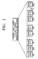
- FIG. 1 shows the IS-95/IS-95A forward link in which channels are separated by Walsh orthogonal codes.
- the number of available Walsh orthogonal codes is dependent on the employed modulation method and the minimum data rate.
- future CDMA mobile communication systems will require a greater number of channels assigned to users in order to improve performance.
- future CDMA mobile communication systems will employ traffic channels, pilot channels and control channels, thereby increasing channel capacity.
- the IMT-2000 CDMA communication system using the quasi-orthogonal code of the complex quasi-orthogonal sequence employs QPSK orthogonal modulation.
- the Walsh orthogonal codes undergo QPSK modulation the spreading scheme for specific common channels such as pilot channels and sync channels cannot maintain the backward compatibility with the existing IS-95 system employing BPSK modulation.
- US 5,309,474 relates to a system and method for communicating information in a mobile cellular telephone system or satellite mobile telephone system using spread spectrum communication signals.
- spread spectrum communication techniques particularly CDMA techniques
- the waveform design implemented in a spread spectrum cellular telephone system involves a direct sequence pseudonoise spread spectrum carrier.
- the carrier waveform design for the cell-site transmitted signals utilizes a sinusoidal carrier that is quadraphase (four phase) modulated by a pair of binary PN sequences that provide the outer code transmitted by a single sector or cell.
- the sequences are generated by two different PN generators of the same sequence length.
- One sequence bi-phase modulates the in-phase channel (I Channel) of the carrier and the other sequence bi-phase modulates the quadrature phase (Q Channel) of the carrier.
- the resulting signals are summed to form a composite four-phase carrier.
- channel transmitters include a BPSK orthogonal spreader and a QPSK orthogonal spreader to selectively spread transmission signals by BPSK modulation or QPSK modulation in a CDMA communication system.
- channel receivers include a BPSK orthogonal despreader and a QPSK orthogonal despreader to selectively despread received signals by BPSK demodulation or QPSK demodulation in a CDMA communication system.
- channel transmitters include an orthogonal spreader for orthogonally spreading transmission signals by BPSK modulation using a Walsh orthogonal code and an orthogonal spreader for orthogonally spreading transmission signals by QPSK modulation using a Walsh orthogonal code or a quasi-orthogonal code, thereby to selectively spread the transmission signals by BPSK modulation or QPSK modulation in a CDMA communication system.
- channel receivers include an orthogonal despreader for orthogonally despreading spread signals by BPSK demodulation using a Walsh orthogonal code and an orthogonal despreader for orthogonally despreading spread signals by QPSK demodulation using a Walsh orthogonal code or a quasi-orthogonal code, thereby to selectively despread the spread signals by BPSK demodulation or QPSK demodulation in a CDMA communication system.
- a channel spreading device for a base station in a CDMA communication system.
- the device comprises a spreading code generator for generating a real-component spreading code and an imaginary-component spreading code corresponding to a designated channel spreading code index; a circuit receiving a mode control signal, for disabling generation of the imaginary-component spreading code when the received mode control signal indicates a BPSK (Binary Phase Shift Keying) modulation mode; and a complex multiplier receiving a channel signal, for complex multiplying the received channel signal by at least one spreading codes to spread the channel signal.
- BPSK Binary Phase Shift Keying
- the spreading code generator comprises a controller for generating a quasi-orthogonal code mask index and a Walsh orthogonal code index corresponding to the designated channel spreading code index; a real-component spreading code generator for generating a real-component quasi-orthogonal code mask corresponding to the quasi-orthogonal code mask index, generating a real-component Walsh orthogonal code corresponding to the Walsh orthogonal code index, and generating a real-component channel spreading code by multiplying the real-component quasi-orthogonal code mask by the real-component Walsh orthogonal code; an imaginary-component spreading code generator for generating an imaginary-component quasi-orthogonal code mask corresponding to the quasi-orthogonal code mask index, generating an imaginary-component Walsh orthogonal code corresponding to the Walsh orthogonal code index, and generating an imaginary-component channel spreading code by multiplying the imaginary-component quasi-orthogonal code mask by the imaginary-component Walsh orthogonal code.
- the terms “orthogonal spreading” and “channel spreading” will be used interchangeably, and the terms “PN spreading” and “spreading” will also be used interchangeably.
- the term “spreading code” covers the terms “Walsh orthogonal code” and “quasi-orthogonal code”, and the term “orthogonal code index” refers to both a Walsh orthogonal code index and a quasi-orthogonal code mask index used in index tables for creating a Walsh orthogonal code and a quasi-orthogonal code, respectively.
- first spreading code refers to a real-component spreading code and the term “second spreading code” refers to an imaginary-component spreading code.
- a system performing orthogonal spreading and despreading by QPSK modulation and demodulation will be referred to as an "IMT-2000 system", and a system performing orthogonal spreading and despreading by BPSK modulation and demodulation will be referred to as an "IS-95 system”.
- a "specific channel” includes the channels requiring backward compatibility with the IS-95 system, such as the pilot channel, the sync channel and paging channels, and it is assumed that such specific channels have a BPSK spreading scheme.
- the channels other than the specific channels, which do not require backward compatibility with the IS-95 system will be referred to as "non-specific channels", and it is assumed that such non-specific channels have a QPSK spreading scheme.
- the non-specific channels include the dedicated control channel, the dedicated supplemental channel, and the common channel proposed for the IMT-2000 system.
- an embodiment of the present invention will also be described on the assumption that channel spreading is performed by BPSK modulation using a Walsh orthogonal code.
- a Walsh orthogonal code or a quasi-orthogonal code is selectively used for channel spreading by QPSK modulation. Therefore, an orthogonal spreader according to the present invention can perform orthogonal spreading by either BPSK or QPSK modulation, and in addition, can selectively use a Walsh orthogonal code or a quasi-orthogonal code as the channel spreading code when performing orthogonal spreading by QPSK modulation.
- a CDMA communication system has a BPSK spreading scheme for the channels requiring backward compatibility with the IS-95 system, and has a QPSK spreading scheme for the other channels not requiring backward compatibility.
- FIG. 6 shows various channels used in a forward link of a CDMA communication system according to a first embodiment of the present invention.
- the channels used in the forward link of the IMT-2000 system include a pilot channel, a sync channel, a paging channel, a traffic channel, a common channel, a dedicated control channel, a fundamental channel and a supplemental channel.
- the pilot channel, the sync channel, the paging channel and the traffic channel are used in the IS-95 system, while the other channels are newly proposed for the IMT-2000 system. Therefore, the "specific channels” include some or all of the channels used in the IS-95 system, and the "non-specific channels” include the other channels.
- the specific channels requiring backward compatibility with the IS-95 system use a BPSK spreading scheme, and the other channels use a QPSK spreading scheme.
- a mode controller 600 which determines whether or not a base station is presently in communication with IS-95 mobile stations, to designate a proper spreading scheme to the respective channels.
- whether or not the base station is in communication with the IS-95 mobile stations can be recognized through a field indicating the mobile station type (IS-95 mobile station or IMT-2000 mobile station) or a field indicating a version of the mobile station, included in an access request message transmitted from the mobile station to the base station.
- Control signals of the mode controller 600 include a select signal SEL for separating a channel signal into a real-component signal and an imaginary-component signal, and mode control signals for determining a spreading mode of the respective transmitters.
- FIG. 7 shows a procedure, performed by the mode controller 600, for setting an orthogonal spreading mode of the respective channels by analyzing an access message received from the mode controller 600.
- some channels should include orthogonal spreaders for performing BPSK and QPSK orthogonal modulation modes of operation.
- a mobile station sends a message including information for distinguishing the mobile station type (IS-95 mobile station or IMT-2000 mobile station) to a base station (BS) over an access channel, in step 711.
- the base station Upon receipt of the information about the mobile station type, the base station recognizes the mobile station type by analyzing the received access channel message and sends the mode controller 600 the received information together with information about the channel over which the base station will send a message to the mobile station, in step 713.
- the mode controller 600 then outputs mode control signals for designating an orthogonal spreading mode of the respective channels shown in FIG. 6 according to the mobile station type, in step 715.
- the respective channels set their orthogonal spreading modes according to the mode control signals from the mode controller 600.
- the respective channels select BPSK or QPSK modulation for orthogonal spreading according to the mode control signals, to orthogonally spread signals to be transmitted.
- the respective channels of the base station orthogonally spread the transmission signals by BPSK or QPSK modulation according to the mobile station type and transmit the spread transmission signals, in step 717.
- the common channels such as the pilot channel and the sync channel constantly transmit corresponding channel signals to every mobile station prior to receiving the access channel message from the mobile station, they can be fixed in the BPSK orthogonal spreading mode. Therefore, in order to demodulate some common channel signals such as the pilot channel signal and the sync channel signal, every IMT-2000 mobile station can also be fixed in the channel spreading mode of BPSK modulation. Further, in the IMT-2000 mobile stations, the channels not requiring backward compatibility with the IS-95 terminal can be fixed in the channel spreading mode of QPSK modulation.
- the IMT-2000 system can use the channel spreading mode of BPSK modulation for the channels currently used in the IS-95 system, and selectively use the channel spreading mode of BPSK or QPSK modulation for the channels (e.g., the fundamental traffic channel) used in both the IMT-2000 system and the IS-95 system.
- channels e.g., the fundamental traffic channel
- the respective channel transmitters of FIG. 6 should have both the BPSK channel spreading scheme and the QPSK channel spreading scheme.
- the specific common channels such as the pilot channel and the sync channel are fixedly set to the BPSK channel spreading mode in every base station
- the mobile station may have only the BPSK channel spreading scheme regardless of the IS-95 system or the IMT-2000 system.
- the channels not requiring backward compatibility with the IS-95 mobile station such as the dedicated control channel and the supplemental channel (which are newly proposed for the IMT-2000 system), are fixedly set to the QPSK channel spreading mode in the base station, and the corresponding IMT-2000 mobile station can have only the QPSK channel spreading scheme.
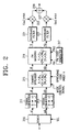
- FIGS. 2 to 5 show channel transmitters and channel receivers according to an embodiment of the present invention. More specifically, FIGS. 2 and 4 show channel transmitters of a forward link according to an embodiment of the present invention.
- FIG. 2 shows a channel transmitter wherein a channel spreader 215 has a channel spreading scheme of QPSK modulation
- FIG. 4 shows a channel transmitter wherein a channel spreader 400 has a channel spreading scheme of BPSK modulation.
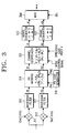
- FIGS. 3 and 5 show channel receivers of the forward link according to an embodiment of the present invention.
- FIG. 3 shows a channel receiver wherein a channel despreader 321 has a channel despreading scheme of QPSK demodulation
- FIG. 5 shows a channel receiver wherein a channel despreader 500 has a channel despreading scheme of BPSK demodulation.
- an input signal 'a' is applied to a demultiplexer 200 after channel coding, rate matching and interleaving. Further, a select signal SEL output from the mode controller 600 is applied to the demultiplexer 200 so as to demultiplex (or separate) the input signal 'a' into odd symbols aI and even symbols aQ, which are applied to a signal converter 211 and a signal converter 213, respectively. Therefore, the demultiplexer 200 demultiplexes the input signal 'a' into the odd signal aI and the even signal aQ according to the select signal SEL.
- the signal converter 211 converts a signal '0' to '+1' and a signal '1' to '-1' for the input signal aI, to output a signal dI.
- the signal converter 213 converts a signal '0' to '+1' and a signal '1' to '-1' for the input signal aQ, to output a signal dQ.
- a channel spreader 215 determines its modulation method according to a mode control signal output from the mode controller 600. Further, the channel spreader 215 includes generators for generating real-component and imaginary-component spread signals according to a received spreading code index k.
- the channel spreader 215 receiving the signals dI and dQ output from the signal converters 211 and 213 and the spreading code index k, multiplies (for complex spreading) the spreading codes corresponding to the spreading code index k by the signals dI and dQ, to generate channel spread signals XI and XQ.
- the mode control signal applied to the channel spreader 215 designates a QPSK modulation mode.
- the spreading code generated according to the spreading code index k becomes the real-component spreading code and the imaginary-component spreading code corresponding to the spreading code index k.
- the spreading codes are Walsh orthogonal codes
- a PN code generator 217 generates PN codes PNI and PNQ for spreading the orthogonally spread signals XI and XQ.
- the PN codes can be short PN sequences.
- a baseband filter 221 filters the spread signal YI into a baseband signal, and a baseband filter 223 filters the spread signal YQ into a baseband signal.
- a mixer 225 multiplies an output of the baseband filter 221 by a carrier cos2 ⁇ fct to convert the output signal into a RF (Radio Frequency) signal.
- a mixer 227 multiplies an output of the baseband filter 223 by a carrier sin2 ⁇ fct to convert the output signal into a RF signal.
- An adder (or exclusive OR operator) 229 adds outputs of the mixers 225 and 227 to output a transmission signal.
- the input signals al and aQ each having the values of '0' and '1', are converted by the signal converters 211 and 213 into the signals dI and dQ each having the values of '+1' and '-1'.
- the channel spreader 215 orthogonally spreads the signals dI and dQ according to the spreading code index k.
- the channel transmitter orthogonally spreads the input signal 'a' by QPSK modulation and the demultiplexer 200 demultiplexes the input signal 'a' into the signals aI and aQ.
- FIG. 3 shows a forward channel receiver for channel despreading the spread signal received from the forward link channel transmitter of FIG. 2 by QPSK demodulation.
- a mixer 311 mixes a received signal with a carrier cos2 ⁇ fct, and a mixer 313 mixes the received signal with a carrier sin2 ⁇ fct.
- a baseband filter 315 filters a signal output from the mixer 311 into a baseband signal, and a baseband filter 317 filters a signal output from the mixer 313 into another baseband signal.
- a PN code generator 318 generates PN codes PNI and PNQ for despreading the received spread signals.
- a channel despreader 321 determines its demodulation mode (BPSK or QPSK modulation) for orthogonal despreading according to a control signal output from a controller of the mobile station (not shown in FIG. 3), and receives the despread signals XI and XQ and their associated walsh code indexes k.
- the channel despreader 321 generates the real-component spreading code and the imaginary-component spreading code corresponding to the spreading code indexes k. Further, the channel despreader 321 multiplies the input signals XI and XQ by the real-component spreading code and the imaginary-component spreading code, respectively, according to the designated demodulation mode, to generate channel despread signals dI and dQ.
- a signal converter 323 converts a signal '+1' to '0' and a signal '-1' to '1' for the signal dI output from the channel despreader 321.
- a signal converter 325 converts a signal '+1' to '0' and a signal '-1' to '1' for the signal dQ output from the channel despreader 321.
- the signals aI and aQ output from the signal converters 323 and 325 are applied to a multiplexer 300, which multiplexes the demodulated signals aI and aQ output from the signal converters 323 and 235 according to a control signal SEL from the controller. That is, in the QPSK mode of operation, the multiplexer 300 multiplexes the signals aI and aQ.
- the output signal 'a' of the multiplexer 300 is applied to a combiner in the following stage, and used for channel estimation.
- the PN masking part 319 and the channel despreader 321 constitute one finger.
- the mobile station includes a plurality of such fingers each comprised of the PN masking part 319 and the channel despreader 321.
- the signals XI and XQ output from the PN masking part 319 are input to the channel despreader 321 together with the spreading code index k.
- the spreading code index k is known to both the base station and the mobile station through previous communication.
- the spreading code is assumed to be a Walsh orthogonal code.
- the signals XI and XQ input to the channel despreader 321 can be expressed as complex values of XI+jXQ, and those values are multiplied by a complex conjugate value Wk-jWk of the complex Walsh orthogonal code Wk+jWk.
- FIG. 4 shows a channel transmitter having a scheme for performing channel spreading by BPSK modulation in a CDMA communication system.
- the base station channel transmitter of FIG. 4 has the same structure as the channel transmitter of FIG. 2 except the structure of a channel spreader 400. That is, the channel spreader 400 performs channel spreading by BPSK modulation.
- the mode controller 600 generates control signals for operating a demultiplexer 402 and the channel spreader 400 in the BPSK channel spreading mode.
- an input signal 'a' is applied to the demultiplexer 402 after channel coding, rate matching and interleaving.
- the mode controller 600 When the mode controller 600 generates a select signal SEL for selecting the BPSK mode, the signal 'a' is not applied to the signal converter 213, but only to the signal converter 211.
- the signals aI having the values of '0' and '1', output from the demultiplexer 402, are converted to the values '+1' and '-1' in the signal converters 211.
- the signal dQ can have a specific logic value of '0'.
- the channel spreader 400 is set to the BPSK modulation mode according to the mode control signal, and receives the signals dI and dQ together with the orthogonal code index k for orthogonal spreading. Then, the channel spreader 400 generates a spreading code corresponding to the input channel spreading code index, wherein the generated spreading code can be a real-component Walsh orthogonal code Wk. Thereafter, the channel spreader 400 mixes the generated spreading code with the input signals dI and dQ to generate channel spread signals.
- FIG. 5 shows a mobile station receiver for demodulating a spread signal received from the base station transmitter of FIG 4 having the BPSK channel spreader.
- the mobile station receiver of FIG. 5 also has the same structure as the channel receiver of FIG. 3 except for the channel despreader 500. That is, the channel despreader 500 performs channel despreading by BPSK demodulation.
- the mode control signal applied to the channel despreader 500 designates the BPSK demodulation mode.
- a multiplexer 502 blocks the signal aQ output from the signal converter 325 in the BPSK demodulation mode according to the select signal SEL.
- the signals XI and XQ output from the PN masking part 319 are input to the channel despreader 500 together with the spreading code index k.
- the spreading code index k is known to both the base station and the mobile station through previous communication.
- the channel despreader 500 is set to the BPSK demodulation mode according to the control signal output from a controller of the mobile station (not shown in FIG. 5), and generates a spreading code corresponding to the spreading code index.
- the channel despreader 500 generates a real-component Walsh orthogonal code Wk for the spreading code.
- the channel despreader 500 mixes the generated Walsh orthogonal code Wk with the input signals XI and XQ to generate channel despread signals dI and dQ.
- the signals XI and XQ can be expressed as complex values of XI+jXQ, and those values are multiplied by the Walsh orthogonal code Wk in the channel despreader 500.
- the channel despreader 500 outputs the accumulated values.
- the IS-95 system uses BPSK orthogonal spreading
- the IMT-2000 system uses QPSK orthogonal spreading.
- Communication cannot be performed between a base station of the IMT-2000 system and a mobile station of the IS-95 system or between a base station of the IS-95 system and a mobile station of the IMT-2000 system.
- the IMT-2000 base station When the channel transmitters and channel receivers for the forward link are constructed as described above, the IMT-2000 base station operates, upon detecting the IS-95 mobile station, the common channels such as the pilot channel, the sync channel and the paging channel in the BPSK channel spreading mode.
- the base station having the BPSK channel transmitter of FIG. 4 channel spreads the signals on the common channels by BPSK modulation before transmission.
- the mobile station Upon initial setup (or power-on), the mobile station should send its information to know its channel spreading mode to the base station.
- the base station When the mobile station transmits to the base station an access channel message including information indicating that it is an IS-95 mobile station, the base station recognizes that the counterpart mobile station is an IS-95 mobile station by analyzing the received access channel message, and then transmits a channel assignment message for BPSK modulation over the paging channel. Thereafter, the base station and the mobile station communicate with each other by performing channel spreading and despreading in the BPSK mode.
- the mobile station sends its channel spreading mode information during the initial setup
- the IS-95 base station upon detecting the IMT-2000 mobile station, the IS-95 base station operates in the BPSK channel spreading mode to receive the common channels such as the pilot channel, the sync channel and the paging channel.
- the multiplexer 502 selectively outputs only the despread signal aI output from the signal converter 323 excluding the despread signal aQ, and the output signal of the multiplexer 502 undergoes decoding in the following stage, thereby providing backward compatibility with the IS-95 base station. Therefore, the IS-95 base station can receive a signal transmitted from the IMT-2000 mobile station.
- the IS-95 base station sends a channel assignment message including the base station type information indicating that it is an IS-95 base station upon receipt of the access channel message.
- the IMT-2000 mobile station then recognizes that the counterpart base station is an IS-95 base station, and sets the channel spreading mode to BPSK mode.
- the IS-95 base station and the IMT-2000 mobile station communicate with each other by performing channel spreading and despreading in the BPSK mode.
- FIGS. 8 and 9 show channel spreaders using BPSK modulation and QPSK modulation, respectively.
- the channel spreading is performed in the latter method.
- FIG. 8 shows the channel spreader 400 in the BPSK channel transmitter of FIG. 4.
- a spreading code generator 811 having a spreading code table, generates a spreading code corresponding to an input spreading code index k.
- a multiplier 813 multiplies the input signal dI by the generated spreading code to generate a channel spread I-channel signal XI.
- a multiplier 815 multiplies the input signal dQ by the generated spreading code to generate a channel spread Q-channel signal XQ.
- the spreading code can be a Walsh code.
- the input signals dI and dQ are input to the multipliers 813 and 815, respectively.
- the spreading code index k for designating a specific spreading code is input to the spreading code generator 811.
- the spreading code generator 811 generates a spreading code corresponding to the spreading code index k and provides the generated spreading code to the multipliers 813 and 815.
- the multiplier 813 then multiplies the input signal dI by the spreading code to generate an output signal XI, and the multiplier 815 multiplies the input signal dQ by the spreading code to generate an output signal XQ.
- FIG. 9 shows the channel spreader 215 in the QPSK channel transmitter of FIG. 2.
- first and second spreading code generators 911 and 913 each receive the spreading code index k, and generate a first spreading code of the real component and a second spreading code of the imaginary component each corresponding to the spreading code index k.
- the first and second spreading codes output from the first and second spreading code generators 911 and 913 are the I-component spreading code and the Q-component spreading code, respectively.
- a multiplier 915 multiplies the input signal dI by the first spreading code generated from the first spreading code generator 911
- a multiplier 917 multiplies the input signal dQ by the first spreading code generated from the first spreading code generator 911.
- the structure comprised of the first spreading code generator 911 and the multipliers 915 and 917 is identical to the BPSK channel spreader of FIG. 8.
- a multiplier 919 multiplies the input signal dI by the second spreading code output from the second spreading code generator 913, and a multiplier 921 multiplies the input signal dQ by the second spreading code output from the second spreading code generator 913.
- An adder 923 subtracts an output of the multiplier 921 from an output of the multiplier 915 to generate an output signal XI.
- An adder 925 adds an output of the multiplier 919 to an output of the multiplier 917 to generate an output signal XQ.
- the input signal dI is applied to the multipliers 915 and 919, and the input signal dQ is applied to the multipliers 917 and 921.
- the first and second spreading code generators 911 and 913 generate an I-component spreading code and a Q-component spreading code, respectively, corresponding to the received spreading code index k.
- the I-component spreading code is input to the multipliers 915 and 917.
- the multiplier 915 then multiplies the I-component input signal dI by the I-component spreading code and provides its output to the adder 923.
- the multiplier 917 multiplies the Q-component input signal dQ by the I-component spreading code and provides its output to the adder 925.
- the Q-component spreading code is input to the multipliers 919 and 921.
- the multiplier 919 multiplies the I-component input signal dI by the Q-component spreading code and provides its output to the adder 925.
- the adder 925 then adds a signal output from the multiplier 917 to a signal output from the multiplier 919 to generate an output signal XQ.
- the multiplier 921 multiplies the Q-component input signal dQ by the Q-component spreading code and provides its output to the adder 923.
- the adder 923 then subtracts an output signal of the multiplier 921 from an output signal of the multiplier 915 to generate an output signal XI.
- FIG. 10 shows the spreading code generator in the channel spreaders of FIGS. 8 and 9.
- the spreading code can be Walsh orthogonal code or a quasi-orthogonal code.
- the quasi-orthogonal code is generated by mixing the Walsh orthogonal code with a quasi-orthogonal code mask.
- a device and method for generating the quasi-orthogonal code is disclosed in detail in Korean patent application No. 97-47457, filed by the applicant.
- a complex quasi-orthogonal sequence for QPSK modulation is disclosed in Korean patent application No. 98-37453 (corresponding International Application No.: PCT/KR99/00532 filed on September 8, 1999), filed by the applicant.
- a controller 1011 calculates a quasi-orthogonal code mask index and a Walsh orthogonal code index for generating quasi-orthogonal code corresponding to the received spreading code index k.
- a quasi-orthogonal code mask generator 1013 having a quasi-orthogonal code mask table, selects a quasi-orthogonal code mask corresponding to the quasi-orthogonal code mask index from the table.
- a Walsh orthogonal code generator 1015 having a Walsh orthogonal code table, selects a Walsh orthogonal code corresponding to the Walsh orthogonal code index from the table.
- a multiplier 1017 multiplies the quasi-orthogonal code mask by the Walsh orthogonal code to generate a spreading code.
- the quasi-orthogonal code mask generator 1013 When a quasi-orthogonal code mask index is not selected, the quasi-orthogonal code mask generator 1013 does not generate a quasi-orthogonal code mask, so the multiplier 1017 outputs the Walsh orthogonal code output from the Walsh orthogonal code generator 1015 as the spreading code.
- the quasi-orthogonal code mask generator 1013 outputs a quasi-orthogonal code mask, the spreading code output from the multiplier 1017 becomes a quasi-orthogonal code.
- the spreading code generator includes the first spreading code generator 911 for generating the I-component (or real-component) spreading code and the second spreading code generator 913 for generating the Q-component (or imaginary-component) spreading code.
- the first and second spreading code generators each have the structure shown in FIG. 10.
- the first and second spreading code generators 911 and 913 can use the same spreading code index k.
- the controller 1011 for the spreading code generators 911 and 913 generates a quasi-orthogonal code mask index and a Walsh orthogonal code index according to the received spreading code index k, and the generated quasi-orthogonal code mask index and Walsh orthogonal code index are identical to each other.
- a real-component Walsh orthogonal code or a imaginary-component Walsh orthogonal code generated from the Walsh orthogonal code generator 1015 is the same Walsh orthogonal code
- the real-component quasi-orthogonal code mask or the imaginary-component quasi-orthogonal code mask generated from the quasi-orthogonal code mask generator 1013 can be different quasi-orthogonal code masks.
- the real-component quasi-orthogonal code mask values and the imaginary-component quasi-orthogonal code mask values stored in an internal memory of the quasi-orthogonal code mask generator 103 are different, the I-component mask output and the Q-component mask output become different even though the same mask index is received. It is also possible to implement the memory having the mask values with the hardware for generating a mask value according to an index.
- the spreading code generators 911 and 913 receive the same spreading code index k. However, it is also possible to use different indexes for generating the real-component spreading code and the imaginary-component spreading code.
- the quasi-orthogonal code mask generator 1013 includes separate tables for storing the real-component and imaginary-component quasi-orthogonal code masks
- the Walsh orthogonal code generator 1015 includes a phase shifter, disposed at an output stage thereof, for generating the imaginary-component Walsh orthogonal code.
- the multiplier 1017 is constructed with a first multiplier and a second multiplier, wherein the first multiplier multiplies the real-component quasi-orthogonal code mask by the Walsh orthogonal code and the second multiplier multiplies the imaginary-component quasi-orthogonal code mask by the Walsh orthogonal code.
- the controller 1011 Upon receipt of the spreading code index k, the controller 1011 calculates a quasi-orthogonal code mask index and a Walsh orthogonal code index corresponding to the received spreading code index k.
- the quasi-orthogonal code mask index is input to the quasi-orthogonal code mask generator 1013, and the Walsh orthogonal code index is input to the Walsh orthogonal code generator 1015.
- the quasi-orthogonal code mask generator 1013 generates a quasi-orthogonal code mask expressed with '+1' and '-1', and provides the generated quasi-orthogonal code mask to the multiplier 1017.
- the Walsh orthogonal code generator 1015 generates a Walsh orthogonal code expressed with '+1' and '-1', and provides the generated Walsh orthogonal code to the multiplier 1017.
- the multiplier 1017 then multiplies the quasi-orthogonal code mask by the Walsh orthogonal code to generate a spreading code.
- the spreading code can be a Walsh orthogonal code or a quasi-orthogonal code.
- the mask value output from the quasi-orthogonal code mask generator 1013 and the Walsh orthogonal code output from the Walsh orthogonal code generator 1015 have the values of '+1' and '-1'.
- the mask value output from the quasi-orthogonal code mask generator 1013 and the Walsh orthogonal code output from the Walsh orthogonal code generator 1015 have the values of '0' and '1' in the spreading code generator 911 (or 913)
- FIG. 15 shows a quasi-orthogonal code mask table and a Walsh orthogonal code table according to the spreading code index k in the spreading code generator 911 (or 913) of FIG. 10.
- the quasi-orthogonal code mask index is set to a specific value '0', which is a system parameter and can be varied, and the quasi-orthogonal code mask generator 1013 receives this index and constantly outputs a signal of '1'. Therefore, the Walsh orthogonal code generator 1015 generates a Walsh orthogonal code corresponding to the Walsh orthogonal code index and outputs the generated Walsh orthogonal code as the spreading code.
- a description will be made with regard to operation of the spreading code generator of FIG. 10 when it generates the quasi-orthogonal code.
- the controller 1011 Upon receipt of the spreading code index k, the controller 1011 generates a quasi-orthogonal code mask index and a Walsh orthogonal code index for generating a quasi-orthogonal code corresponding to the received spreading code index k. Then, the quasi-orthogonal code mask generator 1013 selects a quasi-orthogonal code mask corresponding to the quasi-orthogonal code mask index from the quasi-orthogonal code mask table of FIG. 15, and the Walsh orthogonal code generator 1015 selects a Walsh orthogonal code corresponding to the Walsh orthogonal code index from the Walsh orthogonal code table of FIG. 15. The quasi-orthogonal code mask is mixed with the Walsh orthogonal code by the multiplier 1017 to generate the quasi-orthogonal code.
- the respective channels should be able to support both of the two spreading schemes (i.e., BPSK and QPSK modulation modes), and the two hardware structures can be implemented in this method.
- BPSK and QPSK modulation modes i.e., BPSK and QPSK modulation modes
- a single hardware structure is provided of which spreading scheme is variable according to a mode control command.
- a channel spreader performs orthogonal spreading in the two (BPSK and QPSK) modulation modes.
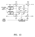
- FIGS. 11 to 14 show the channel spreader 215 or 400 in the channel transmitters of FIGS. 2 and 4, which performs BPSK or QPSK channel spreading by disconnecting or connecting a Q-component spreading code according to a mode control signal.
- the channel spreader has the same structure as the QPSK channel spreader of FIG. 9 except the scheme for selecting a BPSK path and a QPSK path according to the mode control signal from the mode controller 600. That is, the channel spreader of FIG. 11 further includes a switch 1111 interposed between the multiplier 919 and the adder 925, being switching according to the mode control signal, and a switch 1113 interposed between the multiplier 921 and the adder 923, being switched according to the mode control signal. The switches 1111 and 1113 are simultaneously switched by the mode control signal.
- the switches 1111 and 1113 are turned off so that the output signal of the multiplier 919 and the output signal of the multiplier 921 are not applied to the adders 925 and 923. Therefore, the adder 925 adds '0' to the output signal of the multiplier 917, and the adder 923 subtracts '0' from the output signal of the multiplier 915. Accordingly, the output signals XI and XQ are output in the same manner as in the BPSK channel spreader of FIG. 8.
- the channel spreader when the channel spreader is set to the QPSK mode, the switches 1111 and 1113 connect the multipliers 919 and 921 to the adders 925 and 923, respectively so that the output signals of the multipliers 919 and 921 are applied to the adders 925 and 923, respectively. Therefore, the channel spreader serves as the QPSK channel spreader of FIG. 9.
- the channel spreader has the same structure as the QPSK channel spreader of FIG. 9 except the scheme for selecting a BPSK path and a QPSK path according to the mode control signal from the mode controller 600. That is, in the channel spreader of FIG. 12, a gain controller 1211 generates a gain control signal having a first value for the BPSK mode and a second value for the QPSK mode according to the mode control signal output from the mode controller 600. A multiplier 1213 connected between the multiplier 919 and the adder 925, controls an output gain of the multiplier 919 according to the gain control signal. A multiplier 1215 connected between the multiplier 921 and the adder 923, controls an output gain of the multiplier 921 according to the gain control signal.
- the multipliers 1213 and 1215 are provided with the same gain control signal.
- the gain control signal is '0'
- the Q-component signals output from the multipliers 919 and 921 are not applied to the adders 925 and 923.
- the gain control signal is '1'
- the Q-component signals are applied to the adders 925 and 923.
- the mode control signal indicating the BPSK spreading mode is applied to the gain controller 1211.
- the gain controller 1211 outputs the gain control signal having a value '0' to the multipliers 1213 and 1215.
- the multipliers 1213 and 1215 both generate the output signals of '0'. Therefore, the adder 925 adds '0' to the spread signal output from the multiplier 917 and the adder 923 subtracts '0' from the spread signal output from the multiplier 915. Accordingly, the output signals XI and XQ are output in the same manner as in the BPSK channel spreader of FIG. 8.
- the mode control signal indicating the QPSK spreading mode is applied to the gain controller 1211.
- the gain controller 1211 outputs the gain control signal having a value '1' to the multipliers 1213 and 1215.
- the multipliers 1213 and 1215 multiplies the gain control signal '1' by the spread signals output from the multipliers 919 and 921, respectively, so that the output signals of the multipliers 1213 and 1215 become identical to the output signals of the multipliers 919 and 921.
- the output of the multiplier 1213 is applied to the adder 925 and the output of the multiplier 1215 is applied to the adder 923.
- the adder 923 subtracts the output of the multiplier 1215 from the output of the multiplier 915, to generate the channel spread signal XI
- the adder 925 adds the output of the multiplier 1213 to the output of the multiplier 917, to generate the channel spread signal XQ. Accordingly, the channel spread signals XI and XQ are output in the same manner as in the QPSK channel spreader of FIG. 9.
- the channel spreader has the same structure as the QPSK channel spreader of FIG. 9 except the scheme for selecting a BPSK path and a QPSK path according to the mode control signal from the mode controller 600. That is, the channel spreader of FIG. 13 further includes a switch 1311 connected between the second spreading code generator 913 and the multipliers 919 and 921, which is switched according to the mode control signal to control output of the Q-component spreading code.
- the switch 1311 when the channel spreader is set to the BPSK mode, the switch 1311 is switched off, so that an output path of the second spreading code generator 913 is disconnected from the multipliers 919 and 921. Accordingly, the multiplier 919 multiplies the input signal dI by '0' and outputs a resulting value '0' to the adder 925. As a result, the adder 925 outputs a value identical to the output value of the multiplier 917. Similarly, the multiplier 921 multiplies the input signal dQ by '0' and outputs a resulting value '0' to the adder 923. As a result, the adder 923 outputs a value identical to the output value of the multiplier 915. Therefore, the final output values are identical to the output values in the BPSK channel spreader.
- the channel spreader when the channel spreader is set to the QPSK mode, the switch 1311 is turned on, so that the Q-component spreading code generated from the second spreading code generator 913 is normally applied to the multipliers 919 and 921. Thereafter, in the same process as in FIG. 9, the channel spreader generates the QPSK channel spread signals.
- the channel spreader has the same structure as the QPSK channel spreader of FIG. 9 except the scheme for selecting a BPSK path and a QPSK path according to the mode control signal from the mode controller 600. That is, the channel spreader of FIG. 13 further includes a gain controller 1211 for generating a gain control signal according to the mode control signal, and a multiplier 1411 connected between the second spreading code generator 913 and the multipliers 919 and 921, which controls output of the Q-component spreading code according to the mode control signal.
- the gain controller 1211 when the channel spreader is set to the BPSK mode, the gain controller 1211 generates the gain control signal having a value '0' according to the mode control signal.
- the multiplier 1411 then multiplies the output of the second spreading code generator 913 by '0' so that an output path of the spreading code generator 913 is disconnected from the multipliers 919 and 921.
- the multiplier 919 multiplies the input signal dI by '0' and outputs a resulting value '0' to the adder 925.
- the adder 925 outputs a value identical to the output value of the multiplier 917.
- the multiplier 921 multiplies the input signal dQ by '0' and outputs a resulting value '0' to the adder 923.
- the adder 923 outputs a value identical to the output value of the multiplier 915. Therefore, the final output values are identical to the output values in the BPSK channel spreader.
- the gain controller 1211 when the channel spreader is set to the QPSK mode, the gain controller 1211 generates the gain control signal having a value '1' according to the mode control signal.
- the multiplier 1411 then multiplies the output of the second spreading code generator 913 by '1', so that the Q-component spreading code generated from the second spreading code generator 913 is normally applied to the multipliers 919 and 921. Thereafter, in the same process as in FIG. 9, the channel spreader generates the QPSK channel spread signals.
- FIGS. 11 to 14 show 4 types of the channel spreaders supporting both the BPSK and QPSK modulations by using the switch or controlling the signal gain to control output of the Q-component spreading code.
- the channel spreader has the same structure as that of FIG. 9 and selectively serves as the BPSK or QPSK channel spreader by using the spreading code generator.
- FIGS. 17 to 21 show different examples of the channel spreader which selectively serves as the BPSK or QPSK channel spreader by using the spreading code generator.
- FIG. 16 shows I-component quasi-orthogonal code mask index, Q-component quasi-orthogonal code mask index, and Walsh orthogonal code index according to spreading code index.
- a value k between (N+1)*128 and (N+2)*127 is designated as the spreading code index for the channel spreader of FIG. 9 and applied to the I-component spreading code generator 911 and the Q-component spreading code generator 913.
- a description will be made regarding operation of the Q-component channel spreader with reference to FIG. 10.
- the received spreading code index k is input to the controller 1011, which calculates a quasi-orthogonal code mask index and a Walsh orthogonal code index according to the spreading code index k and provides the mask index to the quasi-orthogonal code mask generator 1013 and the Walsh orthogonal code index to the Walsh orthogonal code generator 1015.
- the quasi-orthogonal code mask generator 1013 outputs the quasi-orthogonal code mask of all 0's to the multiplier 1017. Therefore, the Q-component second spreading code generator 913 outputs '0' and thus, the channel spreader of FIG. 9 serves as the BPSK channel spreader.
- FIGS. 17 to 21 show BPSK and QPSK orthogonal spreading methods performed in a different manner from FIGS. 11 to 14.
- the second spreading code generator 913 controls output of its spreading code by controlling output of the quasi-orthogonal code mask generator 1013 or the Walsh orthogonal code generator 1015. That is, in the channel spreader of FIG. 9, the first spreading code generator 911 has the structure shown in FIG. 10 and the second spreading code generator 913 has any one of the structures shown in FIGS. 17 to 21.
- the spreading code generators of FIGS. 17 to 21 have the structure similar to that of FIG. 10, and control output of the second spreading code generator 913 according to the mode control signal output from the mode controller 600. That is, when the mode control signal indicates a QPSK mode control signal, the output signal of the second spreading code generator 913 is normally output. However, when the mode control signal indicates a BPSK mode control signal, the output signal of the second spreading code generator 913 is controlled (or suppressed).
- the spreading code generator compared with FIG. 10, further includes a switch 1711 connected between the quasi-orthogonal code mask generator 1013 and the multiplier 1017. Therefore, when the BPSK mode control signal is generated, the switch 1711 is turned off so that a value '0' is applied to the multiplier 1017. Therefore, the spreading code generator outputs '0' for the spreading code. Accordingly, the multipliers 919 and 921 in FIG. 9 both output '0', so as to perform channel spreading in the BPSK mode. However, when the QPSK mode control signal is generated, the switch 1711 is turned on so that the output of the quasi-orthogonal code mask generator 1013 is applied to the multiplier 1017. Therefore, the multiplier 1017 generates the spreading code by multiplying the output of the Walsh orthogonal code generator 1015 by the quasi-orthogonal code mask. In this manner, it is possible to selectively perform channel spreading in the BPSK or QPSK mode.
- the spreading code generator compared with FIG. 10, further includes a switch 1811 connected between the Walsh orthogonal code generator 1015 and the multiplier 1017. Therefore, when the BPSK mode control signal is generated, the switch 1811 is turned off so that a value '0' is applied to the multiplier 1017. Therefore, the spreading code generator outputs '0' for the spreading code. Accordingly, the multipliers 919 and 921 in FIG. 9 both output '0', so as to perform channel spreading in the BPSK mode. However, when the QPSK mode control signal is generated, the switch 1811 is turned on so that the output of the Walsh orthogonal code generator 1015 is applied to the multiplier 1017. Therefore, the multiplier 1017 generates the spreading code by multiplying the output of the Walsh orthogonal code generator 1015 by the quasi-orthogonal code mask. In this manner, it is possible to selectively perform channel spreading in the BPSK or QPSK mode.
- the spreading code generator compared with FIG. 10, further includes a multiplier 1911 connected between the quasi-orthogonal code mask generator 1013 and the multiplier 1017, and a gain controller 1211 for providing a gain control signal to the multiplier 1911 according to the mode control signal. Therefore, when the BPSK mode control signal is generated, the gain controller 1211 outputs '0' and thus, the multiplier 1911 also outputs '0'. As a result, the multiplier 1017 outputs '0' for the spreading code. Accordingly, the multipliers 919 and 921 in FIG. 9 both output '0', so as to perform channel spreading in the BPSK mode.
- the gain controller 1211 outputs '1' and thus, the multiplier 1911 provides the quasi-orthogonal code mask output form the quasi-orthogonal code mask generator 1013 to the multiplier 1017. Therefore, the multiplier 1017 generates the spreading code by multiplying the output of the Walsh orthogonal code generator 1015 by the quasi-orthogonal code mask. In this manner, it is possible to selectively perform channel spreading in the BPSK or QPSK mode.
- the spreading code generator compared with FIG. 10, further includes a multiplier 2011 connected between the Walsh orthogonal code generator 1015 and the multiplier 1017, and a gain controller 1211 for providing a gain control signal to the multiplier 2011 according to the mode control signal. Therefore, when the BPSK mode control signal is generated, the gain controller 1211 outputs '0' and thus, the multiplier 2011 also outputs '0'. As a result, the multiplier 1017 outputs '0' for the spreading code. Accordingly, the multipliers 919 and 921 in FIG. 9 both output '0', so as to perform channel spreading in the BPSK mode.
- the gain controller 1211 outputs '1' and thus, the multiplier 2011 provides the Walsh orthogonal code output form the Walsh orthogonal code generator 1015 to the multiplier 1017. Therefore, the multiplier 1017 generates the spreading code by multiplying the output of the Walsh orthogonal code generator 1015 by the quasi-orthogonal code mask. In this manner, it is possible to selectively perform channel spreading in the BPSK or QPSK mode.
- the spreading code generator compared with FIG. 10, further includes a gain controller 1211 for providing a gain control signal to the multiplier 1017 according to the mode control signal. Therefore, when the BPSK mode control signal is generated, the gain controller 1211 outputs '0' and thus, the multiplier 1017 also outputs '0' for the spreading code. Accordingly, the multipliers 919 and 921 in FIG. 9 both output '0', so as to perform channel spreading in the BPSK mode. However, when the QPSK mode control signal is generated, the gain controller 1211 outputs '1', so that the multiplier 1017 generates the spreading code by multiplying the output of the Walsh orthogonal code generator 1015 by the quasi-orthogonal code mask. In this manner, it is possible to selectively perform channel spreading in the BPSK or QPSK mode.
- FIG. 22 shows a channel despreader 500 of FIG. 5.
- a spreading code generator 2211 having a spreading code table, generates a spreading code corresponding to an input spreading code index k.
- a multiplier 2213 multiplies the channel spread input signal XI by the generated spreading code to generate a channel despread I-channel signal dI.
- a multiplier 2215 multiplies the channel spread input signal XQ by the generated spreading code to generate a channel despread Q-channel signal dQ.
- the input signals XI and XQ are input to the multipliers 2213 and 2215, respectively.
- the spreading code index k for designating a specific spreading code is input to the spreading code generator 2211.
- the spreading code generator 2211 generates a spreading code corresponding to the spreading code index k and provides the generated spreading code to the multipliers 2213 and 2215.
- the multiplier 2213 then multiplies the despread input signal XI by the spreading code to generate a channel despread signal dI, and the multiplier 2215 multiplies the input signal XQ by the spreading code to generate a channel despread signal dQ.
- FIG. 23 shows the channel despreader 321 in the QPSK channel receiver of FIG. 3, wherein the channel despreader 321 has the same structure and operation as the channel spreader of FIG. 9 except the adders 2323 and 2325.
- first and second spreading code generators 2311 and 2313 each receiving the spreading code index k, generate a first spreading code and a second spreading code each corresponding to the spreading code index k.
- the first and second spreading codes output from the first and second spreading code generators 2311 and 2313 are the I-component spreading code and the Q-component spreading code, respectively.
- a multiplier 2315 multiplies the orthogonally spread input signal XI by the first spreading code generated from the first spreading code generator 2311, and a multiplier 2317 multiplies the input signal XQ by the first spreading code generated from the first spreading code generator 2311.
- the structure comprised of the first spreading code generator 2311 and the multipliers 2315 and 2317 is identical to the BPSK channel despreader of FIG. 22.
- a multiplier 2319 multiplies the input signal XI by the second spreading code output from the second spreading code generator 2313, and a multiplier 2321 multiplies the input signal XQ by the second spreading code output from the second spreading code generator 2313.
- An adder 2323 adds an output of the multiplier 2321 to an output of the multiplier 2315 to generate a channel despread output signal dI.
- An adder 2325 subtracts an output of the multiplier 2319 from an output of the multiplier 2317 to generate a channel despread output signal dQ.
- FIGS. 24 to 27 show modified channel despreaders which supports both the BPSK and QPSK modulation by using switches or controlling a gain of the input signal to disconnect or connect the Q-component spreading code.
- the channel despreader has the same structure as the QPSK channel despreader of FIG. 23 except for the scheme of selecting a BPSK path or a QPSK path according to the mode control signal transmitted from the base station together with the channel assignment message. That is, the channel despreader of FIG. 24 further includes a switch 2411 interposed between the multiplier 2319 and the adder 2325, being switching according to the mode control signal, and a switch 2413 interposed between the multiplier 2321 and the adder 2323, being switched according to the mode control signal. The switches 2411 and 2413 are simultaneously switched by the mode control signal.
- the switches 2411 and 2413 are turned off so that the output signal of the multiplier 2319 and the output signal of the multiplier 2321 are not applied to the adders 2325 and 2323. Therefore, the adder 2323 adds '0' to the output signal of the multiplier 2315, and the adder 2325 subtracts '0' from the output signal of the multiplier 2317. Accordingly, the output signals dI and dQ are output in the same manner as in the BPSK channel despreader of FIG. 22.
- the switches 2411 and 2413 connect the multipliers 2319 and 2321 to the adders 2325 and 2323, respectively so that the output signals of the multipliers 2319 and 2321 are applied to the adders 2325 and 2323, respectively. Therefore, the channel despreader serves as the QPSK channel despreader of FIG. 23.
- the channel despreader has the same structure as the channel despreader of FIG. 23 except the scheme for selecting a BPSK path and a QPSK path according to the mode control signal transmitted from the base station together with the channel assignment message.
- a gain controller 2511 generates a gain control signal having a first value for the BPSK mode and a second value for the QPSK mode according to the mode control signal transmitted from the base station.
- a multiplier 2513 connected between the multiplier 2319 and the adder 2325, controls an output gain of the multiplier 2319 according to the gain control signal.
- a multiplier 2515 connected between the multiplier 2321 and the adder 2323, controls an output gain of the multiplier 2321 according to the gain control signal.
- the multipliers 2513 and 2515 are provided with the same gain control signal.
- the gain control signal is '0'
- the Q-component signals output from the multipliers 2319 and 2321 are not applied to the adders 2325 and 2323.
- the gain control signal is '1'
- the Q-component signals are applied to the adders 2325 and 2323.
- the gain controller 2511 continuously outputs the gain control signal having the value '0' to the multipliers 2513 and 2515. Then, the multipliers 2513 and 2515 both generate the output signals of '0'. Therefore, the adder 2323 adds '0' to the despread signal output from the multiplier 2315 and the adder 2325 subtracts '0' from the despread signal output from the multiplier 2317. Accordingly, the output signals dI and dQ are output in the same manner as in the BPSK channel despreader of FIG. 22.
- the gain controller 2511 continuously outputs the gain control signal having the value '1' to the multipliers 2513 and 2515. Then, the multipliers 2513 and 2515 multiplies the gain control signal '1' by the despread signals output from the multipliers 2319 and 2321, respectively, so that the output signals of the multipliers 2513 and 2515 become identical to the output signals of the multipliers 2319 and 2321. The output of the multiplier 2513 is applied to the adder 2325 and the output of the multiplier 2515 is applied to the adder 2323.
- the adder 2325 subtracts the output of the multiplier 2513 from the output of the multiplier 2317, to generate the channel despread signal dQ
- the adder 2323 adds the output of the multiplier 2515 to the output of the multiplier 2315, to generate the channel despread signal dI. Accordingly, the channel despread signals dI and dQ are output in the same manner as in the QPSK channel despreader of FIG. 23.
- the channel despreader has the same structure as the QPSK channel despreader of FIG. 23 except the scheme for selecting a BPSK path and a QPSK path according to the mode control signal transmitted from the base station together with the channel assignment message. That is, the channel despreader of FIG. 26 further includes a switch 2611 connected between the second spreading code generator 2313 and the multipliers 2319 and 2321, which is switched according to the mode control signal to control output of the Q-component spreading code.
- the switch 2611 when the BPSK mode control signal is generated, the switch 2611 is switched off, so that an output path of the second spreading code generator 2313 is disconnected from the multipliers 2319 and 2321. Accordingly, the multiplier 2319 multiplies the input signal XI by '0' and outputs a resulting value '0' to the adder 2325. As a result, the adder 2325 outputs a value identical to the output value of the multiplier 2317. Similarly, the multiplier 2321 multiplies the input signal XQ by '0' and outputs a resulting value '0' to the adder 2323. As a result, the adder 2323 outputs a value identical to the output value of the multiplier 2315. Therefore, the final output values are identical to the output values in the BPSK channel despreader of FIG. 22.
- the switch 2611 is turned on, so that the Q-component spreading code generated from the second spreading code generator 2313 is normally applied to the multipliers 2319 and 2321. Thereafter, in the same process as in FIG. 23, the channel despreader generates the QPSK channel despread signals.
- the channel despreader has the same structure as the QPSK channel despreader of FIG. 23 except the scheme for selecting a BPSK path and a QPSK path according to the mode control signal transmitted from the base station together with the channel assignment message. That is, the channel despreader of FIG. 27 further includes a gain controller 2511 for generating a gain control signal according to the mode control signal, and a multiplier 2711 connected between the second spreading code generator 2313 and the multipliers 2319 and 2321, which controls output of the Q-component spreading code according to the mode control signal.
- the gain controller 2511 when the BPSK mode control signal is generated, the gain controller 2511 generates the gain control signal having a value '0' according to the mode control signal.
- the multiplier 2711 then multiplies the output of the second spreading code generator 2313 by '0' so that an output path of the spreading code generator 2313 is disconnected from the multipliers 2319 and 2321. Accordingly, the multiplier 2319 multiplies the input signal XI by '0' and outputs a resulting value '0' to the adder 2325. As a result, the adder 2325 outputs a value identical to the output value of the multiplier 2317.
- the multiplier 2321 multiplies the input signal XQ by '0' and outputs a resulting value '0' to the adder 2323.
- the adder 2323 outputs a value identical to the output value of the multiplier 2315. Therefore, the final output values are identical to the output values in the BPSK channel despreader.
- the gain controller 2511 when the QPSK mode control signal is generated, the gain controller 2511 generates the gain control signal having a value '1' according to the mode control signal.
- the multiplier 2711 then multiplies the output of the second spreading code generator 2313 by '1', so that the Q-component spreading code generated from the second spreading code generator 2313 is normally applied to the multipliers 2319 and 2321. Thereafter, in the same process as in FIG. 23, the channel despreader generates the QPSK channel despread signals.
- the spreading code generators 2311 and 2313 can be implemented as shown in FIG. 10. That is, the spreading code generators 2311 and 2313 each have a quasi-orthogonal code mask index table for generating a quasi-orthogonal code and a Walsh orthogonal code index table for generating a Walsh orthogonal code, and generate a corresponding Walsh orthogonal code or quasi-orthogonal code under the control of a undepicted controller.
- the channel despreader generates only the Walsh orthogonal code for the spreading code in the BPSK mode, and can generate the Walsh orthogonal code or the quasi-orthogonal code in the QPSK mode.
- the spreading code generators 2311 and 2313 have the tables shown in FIGS. 15 and 16.
- the channel despreaders of FIGS. 23 to 27 internally select the BPSK or QPSK modulation mode to perform channel despreading. That is, in the BPSK mode of operation, the channel despreaders of FIGS. 23 to 27 disconnects the path of the imaginary-component spreading code output from the second spreading code generator 2313 and forms only the path of the real-component spreading code output from the first spreading code generator 2311. Further, in the QPSK mode of operation, the channel despreaders despread the received channel spread signals by using both the real-component and imaginary-component spreading codes generated from the first and second spreading code generators 2311 and 2313.
- the channel despreaders can obtain the same results as in FIGS. 24 to 27 by controlling output of the second spreading code generator 2313. Therefore, when the second spreading code generator 2313 is constructed as shown in FIGS. 17 to 21, the channel despreaders can obtain the same results in performing BPSK and QPSK channel spreading.
- this novel channel spreader can select a corresponding channel spreading method according to the mode control signal.
- this novel channel spreader can support both the IS-95 channels and the IMT-2000 channels.
Landscapes
- Engineering & Computer Science (AREA)
- Computer Networks & Wireless Communication (AREA)
- Signal Processing (AREA)
- Mobile Radio Communication Systems (AREA)
Claims (11)
- Dispositif d'étalement de canal (215, 400) pour une station de base dans un système de communication AMRC, comprenant un générateur de code d'étalement (811, 911, 913, 2211, 2311, 2313) pour générer un code d'étalement de composante réelle et un code d'étalement de composante imaginaire correspondant à un index de code d'étalement de canal désigné, caractérisé en ce que
le dispositif d'étalement de canal comprend en outre :un circuit recevant un signal de commande de mode, pour désactiver la génération du code d'étalement de composante imaginaire lorsque le signal de commande de mode reçu indique un mode de modulation BPSK; etun multiplieur complexe (915, 917, 919, 921, 2315, 2317, 2319, 2321) recevant un signal de canal, pour effectuer une multiplication complexe du signal de canal reçu par au moins un code d'étalement, pour étaler le signal de canal. - Dispositif d'étalement de canal selon la revendication 1, dans lequel le générateur de code d'étalement comprend :une unité de commande (1011) pour générer un index de masque de code quasi-orthogonal et un index de code orthogonal de Walsh correspondant à l'index de code d'étalement de canal désigné;un générateur de code d'étalement de composante réelle (911) pour générer un masque de code quasi-orthogonal de composante réelle correspondant à l'index de masque de code quasi-orthogonal, pour générer en outre un code orthogonal de Walsh de composante réelle correspondant à l'index de code orthogonal de Walsh, et pour générer en outre un code d'étalement de canal de composante réelle en multipliant le masque de code quasi-orthogonal de composante réelle par le code orthogonal de Walsh de composante réelle; etun générateur de code d'étalement de composante imaginaire (913) pour générer un masque de code quasi-orthogonal de composante imaginaire correspondant à l'index de masque de code quasi-orthogonal, pour générer en outre un code orthogonal de Walsh de composante imaginaire correspondant à l'index de code orthogonal de Walsh, et pour générer un code d'étalement de canal de composante imaginaire en multipliant le masque de code quasi-orthogonal de composante imaginaire par le code orthogonal de Walsh de composante imaginaire.
- Dispositif d'étalement de canal selon la revendication 2, dans lequel l'unité de commande ne génère pas l'index de masque de code quasi-orthogonal lorsque l'unité de commande reçoit un index de code d'étalement de canal qui désigne un code orthogonal de Walsh.
- Dispositif d'étalement de canal selon la revendication 2 ou 3, dans lequel le circuit pour désactiver la génération du code d'étalement de canal de composante imaginaire est connecté à un noeud de sortie du générateur de code d'étalement de composante imaginaire.
- Dispositif d'étalement de canal selon l'une des revendications 2 à 4, dans lequel le circuit pour désactiver la génération du code d'étalement de canal de composante imaginaire est connecté à des noeuds de sortie de multiplieurs, dans le multiplieur complexe, pour multiplier le code d'étalement de composante imaginaire par le signal de canal, lorsque le signal de commande de mode reçu indique le mode de modulation BPSK.
- Dispositif d'étalement de canal selon l'une des revendications 2 à 5, dans lequel le circuit pour désactiver la génération du code d'étalement de canal de composante imaginaire est disposé dans le générateur de code d'étalement de composante imaginaire.
- Dispositif de désétalement de canal (321, 500) pour une station mobile dans un système de communication AMRC, comprenant un générateur de code d'étalement (811, 911, 913, 2211, 2311, 2313) pour générer un code d'étalement de composante réelle et un code d'étalement de composante imaginaire correspondant à un index de code d'étalement de canal désigné, caractérisé en ce que
le dispositif de désétalement de canal comprend en outre :un circuit recevant un signal de commande de mode, pour désactiver la génération du code d'étalement de composante imaginaire lorsque le signal de commande de mode reçu indique un mode de modulation BPSK; etun multiplieur complexe (915, 917, 919, 921, 2315, 2317, 2319, 2321) recevant un signal de canal pour effectuer une multiplication complexe du signal de canal reçu par les codes d'étalement, pour désétaler le signal de canal. - Procédé d'étalement de canal pour une station de base dans un système de communication AMRC ayant un générateur de code d'étalement (811, 911, 913, 2211, 2311, 2313) pour générer des codes d'étalement de composante réelle et de composante imaginaire, caractérisé en ce que
le procédé d'étalement de canal comprend les étapes suivantes :sous l'effet d'une génération d'un signal de commande de mode BPSK, on désactive la génération du code d'étalement de composante imaginaire et on multiplie un signal de canal à émettre par le code d'étalement de composante réelle, pour étaler le signal de canal; etsous l'effet d'une génération d'un signal de commande de mode QPSK, on effectue une multiplication complexe du signal de canal à émettre par le code d'étalement de composante réelle et le code d'étalement de composante imaginaire, pour étaler le signal de canal. - Procédé de désétalement de canal pour une station mobile dans un système de communication AMRC ayant un générateur de code d'étalement (811, 911, 913, 2211, 2311, 2313) pour générer des codes d'étalement de composante réelle et de composante imaginaire, caractérisé en ce que
le procédé de désétalement de canal comprend les étapes suivantes :sous l'effet d'une génération d'un signal de commande de mode BPSK, on désactive la génération du code d'étalement de composante imaginaire et on multiplie un signal de canal reçu par le code d'étalement de composante réelle pour désétaler le signal de canal; etsous l'effet d'une génération d'un signal de commande de mode QPSK, on effectue une multiplication complexe du signal de canal reçu par le code d'étalement de composante réelle et le code d'étalement de composante imaginaire, pour désétaler le signal de canal. - Procédé d'étalement de canal dans un système de communication AMRC, comprenant les étapes suivantes :on génère, dans une station mobile, un message de canal d'accès incluant une information de mode d'étalement de canal pour un canal de la station mobile, et on émet le message de canal d'accès sur un canal d'accès;à la réception du message de canal d'accès, on détermine, dans une station de base, un mode d'étalement de canal pour un canal de la station de base, correspondant à l'information de mode d'étalement de canal, on génère un message de canal de recherche incluant une information d'étalement de canal correspondant au mode d'étalement de canal déterminé, et on émet le message de canal de recherche;on assigne un canal dédié correspondant au mode d'étalement de canal déterminé et à l'information d'étalement de canal, pour accomplir une communication entre la station de base et la station mobile; etdans lequel le mode d'étalement de canal est la modulation BPSK ou QPSK.
- Procédé d'étalement de canal dans un système de communication AMRC, comprenant les étapes suivantes :on génère, dans une station de base, un message de canal de recherche incluant une information de mode d'étalement de canal d'un canal de la station de base, et on émet le message de canal de recherche sur un canal de recherche;à la réception du message de canal de recherche, on détermine, dans une station mobile, un mode d'étalement de canal pour un canal de la station mobile, correspondant à l'information de mode d'étalement de canal, on génère un message de réponse incluant l'information d'étalement de canal correspondant au mode d'étalement de canal déterminé, et on émet le message de réponse sur un canal d'accès;à la réception du message de canal d'accès, on génère, dans la station de base, un message de canal de recherche incluant l'information d'étalement de canal, correspondant au mode d'étalement de canal, et on émet le message de canal de recherche; eton assigne un canal dédié correspondant au mode d'étalement de canal déterminé et à l'information d'étalement de canal, pour accomplir une communication entre la station de base et la station mobile; etdans lequel le mode d'étalement de canal est la modulation BPSK ou QPSK.
Applications Claiming Priority (5)
| Application Number | Priority Date | Filing Date | Title |
|---|---|---|---|
| KR9849863 | 1998-11-17 | ||
| KR19980049863 | 1998-11-17 | ||
| KR19980050278 | 1998-11-23 | ||
| KR9850278 | 1998-11-23 | ||
| PCT/KR1999/000694 WO2000030280A1 (fr) | 1998-11-17 | 1999-11-17 | Dispositif d'etalement de voie et procede destine a un systeme de communication amcr |
Publications (2)
| Publication Number | Publication Date |
|---|---|
| EP1131909A1 EP1131909A1 (fr) | 2001-09-12 |
| EP1131909B1 true EP1131909B1 (fr) | 2004-10-06 |
Family
ID=26634349
Family Applications (1)
| Application Number | Title | Priority Date | Filing Date |
|---|---|---|---|
| EP19990972390 Expired - Lifetime EP1131909B1 (fr) | 1998-11-17 | 1999-11-17 | Dispositif d'etalement de voie et procede destine a un systeme de communication amcr |
Country Status (9)
| Country | Link |
|---|---|
| US (1) | US6807221B1 (fr) |
| EP (1) | EP1131909B1 (fr) |
| JP (1) | JP3564394B2 (fr) |
| CN (1) | CN100349393C (fr) |
| AU (1) | AU759141B2 (fr) |
| BR (1) | BR9915449A (fr) |
| CA (1) | CA2349222C (fr) |
| DE (1) | DE69920944T2 (fr) |
| WO (1) | WO2000030280A1 (fr) |
Families Citing this family (15)
| Publication number | Priority date | Publication date | Assignee | Title |
|---|---|---|---|---|
| US9525923B2 (en) | 1997-12-17 | 2016-12-20 | Intel Corporation | Multi-detection of heartbeat to reduce error probability |
| US8175120B2 (en) | 2000-02-07 | 2012-05-08 | Ipr Licensing, Inc. | Minimal maintenance link to support synchronization |
| US7394791B2 (en) | 1997-12-17 | 2008-07-01 | Interdigital Technology Corporation | Multi-detection of heartbeat to reduce error probability |
| US7936728B2 (en) | 1997-12-17 | 2011-05-03 | Tantivy Communications, Inc. | System and method for maintaining timing of synchronization messages over a reverse link of a CDMA wireless communication system |
| US6222832B1 (en) | 1998-06-01 | 2001-04-24 | Tantivy Communications, Inc. | Fast Acquisition of traffic channels for a highly variable data rate reverse link of a CDMA wireless communication system |
| US7773566B2 (en) | 1998-06-01 | 2010-08-10 | Tantivy Communications, Inc. | System and method for maintaining timing of synchronization messages over a reverse link of a CDMA wireless communication system |
| US8134980B2 (en) | 1998-06-01 | 2012-03-13 | Ipr Licensing, Inc. | Transmittal of heartbeat signal at a lower level than heartbeat request |
| US8155096B1 (en) | 2000-12-01 | 2012-04-10 | Ipr Licensing Inc. | Antenna control system and method |
| US6954448B2 (en) | 2001-02-01 | 2005-10-11 | Ipr Licensing, Inc. | Alternate channel for carrying selected message types |
| US7551663B1 (en) | 2001-02-01 | 2009-06-23 | Ipr Licensing, Inc. | Use of correlation combination to achieve channel detection |
| WO2002078183A1 (fr) | 2001-03-26 | 2002-10-03 | Japan Science And Technology Corporation | Appareil de filtrage, appareil de reception, appareil de transmission, appareil de modulation de diffusion, appareil de generation de sequences de nombres pseudo-aleatoires, procede de filtrage, procede de reception, procede de transmission, procede de modulation de diffusion, procede de generation de sequences de nombres p |
| ES2624979T3 (es) | 2001-06-13 | 2017-07-18 | Intel Corporation | Aparatos para la transmisión de una señal de latido de corazón a un nivel inferior que la solicitud de latido de corazón |
| US20050094709A1 (en) * | 2001-12-06 | 2005-05-05 | Ismail Lakkis | Ultra-wideband communication apparatus and methods |
| KR20050015119A (ko) * | 2003-08-04 | 2005-02-21 | 삼성전자주식회사 | 광대역 무선 접속 통신 시스템에서 레인징 신호 변조 장치및 방법 |
| US7418047B2 (en) * | 2004-02-25 | 2008-08-26 | Matsushita Electric Industrial Co., Ltd. | Communication apparatus using a plurality of modulation schemes and transmission apparatus composing such communication apparatus |
Family Cites Families (6)
| Publication number | Priority date | Publication date | Assignee | Title |
|---|---|---|---|---|
| US5103459B1 (en) | 1990-06-25 | 1999-07-06 | Qualcomm Inc | System and method for generating signal waveforms in a cdma cellular telephone system |
| EP0767544A3 (fr) * | 1995-10-04 | 2002-02-27 | Interuniversitair Micro-Elektronica Centrum Vzw | Modem programmable utilisant la communication à spectre étalé |
| US6223053B1 (en) * | 1996-06-26 | 2001-04-24 | Cisco Systems, Inc. | Universal radio for use in various cellular communication systems |
| JP3796870B2 (ja) * | 1997-01-21 | 2006-07-12 | ソニー株式会社 | 受信装置及び受信方法、並びに携帯電話システムの端末装置 |
| US6678310B1 (en) | 1998-01-16 | 2004-01-13 | Intersil Americas Inc | Wireless local area network spread spectrum transceiver with multipath mitigation |
| US6603801B1 (en) | 1998-01-16 | 2003-08-05 | Intersil Americas Inc. | Spread spectrum transceiver for use in wireless local area network and having multipath mitigation |
-
1999
- 1999-11-17 EP EP19990972390 patent/EP1131909B1/fr not_active Expired - Lifetime
- 1999-11-17 US US09/442,379 patent/US6807221B1/en not_active Expired - Lifetime
- 1999-11-17 CA CA 2349222 patent/CA2349222C/fr not_active Expired - Fee Related
- 1999-11-17 DE DE1999620944 patent/DE69920944T2/de not_active Expired - Fee Related
- 1999-11-17 JP JP2000583185A patent/JP3564394B2/ja not_active Expired - Lifetime
- 1999-11-17 WO PCT/KR1999/000694 patent/WO2000030280A1/fr not_active Ceased
- 1999-11-17 CN CNB998151270A patent/CN100349393C/zh not_active Expired - Fee Related
- 1999-11-17 AU AU11874/00A patent/AU759141B2/en not_active Ceased
- 1999-11-17 BR BR9915449A patent/BR9915449A/pt not_active IP Right Cessation
Also Published As
| Publication number | Publication date |
|---|---|
| DE69920944D1 (de) | 2004-11-11 |
| DE69920944T2 (de) | 2005-02-03 |
| BR9915449A (pt) | 2001-08-07 |
| CN1332916A (zh) | 2002-01-23 |
| JP3564394B2 (ja) | 2004-09-08 |
| CA2349222C (fr) | 2005-12-06 |
| WO2000030280A1 (fr) | 2000-05-25 |
| AU1187400A (en) | 2000-06-05 |
| CN100349393C (zh) | 2007-11-14 |
| EP1131909A1 (fr) | 2001-09-12 |
| US6807221B1 (en) | 2004-10-19 |
| CA2349222A1 (fr) | 2000-05-25 |
| AU759141B2 (en) | 2003-04-03 |
| JP2002530929A (ja) | 2002-09-17 |
Similar Documents
| Publication | Publication Date | Title |
|---|---|---|
| US6393047B1 (en) | Quadriphase spreading codes in code division multiple access communications | |
| JP3792512B2 (ja) | 移動電気通信システムでのランダムアクセス | |
| RU2184422C2 (ru) | Способ переключения каналов связи в мобильной системе связи, поддерживающей диверсификацию передач | |
| EP1131909B1 (fr) | Dispositif d'etalement de voie et procede destine a un systeme de communication amcr | |
| US6459693B1 (en) | Device and method for cancelling code interference in a CDMA communication system | |
| CA2394957C (fr) | Dispositif et procede pour determiner le debit binaire de rafales de donnees dans un systeme de communication mobile | |
| US9467200B2 (en) | Method and apparatus for orthogonally overlaying variable chip rate spread spectrum signals | |
| US6324171B1 (en) | Multicarrier CDMA base station system and multi-code wave forming method therof | |
| JPH07312783A (ja) | Cdma通信方法および装置 | |
| AU6369999A (en) | Channel assigning device and method in CDMA communication system | |
| US6249517B1 (en) | Apparatus for supporting a variety of transmission rates in spread spectrum CDMA system | |
| AU751845B2 (en) | Channel spreading device and method in CDMA communication system | |
| US6963601B1 (en) | Apparatus and method for spreading channel data in CDMA communication system using orthogonal transmit diversity | |
| JPH10145282A (ja) | Ds−cdma伝送方式 | |
| US20030214924A1 (en) | Apparatus and method for indicating a base station in a mobile station provided in a CDMA communication system | |
| JPH1198550A (ja) | 基地局装置 | |
| KR100346218B1 (ko) | 부호분할다중접속 통신시스템의 채널 확산장치 및 방법 |
Legal Events
| Date | Code | Title | Description |
|---|---|---|---|
| PUAI | Public reference made under article 153(3) epc to a published international application that has entered the european phase |
Free format text: ORIGINAL CODE: 0009012 |
|
| 17P | Request for examination filed |
Effective date: 20010517 |
|
| AK | Designated contracting states |
Kind code of ref document: A1 Designated state(s): AT BE CH CY DE DK ES FI FR GB GR IE IT LI LU MC NL PT SE |
|
| RIN1 | Information on inventor provided before grant (corrected) |
Inventor name: MAENG, SEUNG-JOO Inventor name: KANG, HEE-WON SAMSUNG ELECTRONICS CO., LTD. Inventor name: KIM, YOUNG-KY Inventor name: KIM, JAE-YOEL |
|
| 17Q | First examination report despatched |
Effective date: 20031107 |
|
| GRAP | Despatch of communication of intention to grant a patent |
Free format text: ORIGINAL CODE: EPIDOSNIGR1 |
|
| RAP1 | Party data changed (applicant data changed or rights of an application transferred) |
Owner name: SAMSUNG ELECTRONICS CO., LTD. |
|
| RBV | Designated contracting states (corrected) |
Designated state(s): DE FI FR GB IT SE |
|
| GRAS | Grant fee paid |
Free format text: ORIGINAL CODE: EPIDOSNIGR3 |
|
| GRAA | (expected) grant |
Free format text: ORIGINAL CODE: 0009210 |
|
| AK | Designated contracting states |
Kind code of ref document: B1 Designated state(s): DE FI FR GB IT SE |
|
| REG | Reference to a national code |
Ref country code: GB Ref legal event code: FG4D |
|
| REG | Reference to a national code |
Ref country code: IE Ref legal event code: FG4D |
|
| REF | Corresponds to: |
Ref document number: 69920944 Country of ref document: DE Date of ref document: 20041111 Kind code of ref document: P |
|
| REG | Reference to a national code |
Ref country code: SE Ref legal event code: TRGR |
|
| ET | Fr: translation filed | ||
| PLBE | No opposition filed within time limit |
Free format text: ORIGINAL CODE: 0009261 |
|
| STAA | Information on the status of an ep patent application or granted ep patent |
Free format text: STATUS: NO OPPOSITION FILED WITHIN TIME LIMIT |
|
| 26N | No opposition filed |
Effective date: 20050707 |
|
| PGFP | Annual fee paid to national office [announced via postgrant information from national office to epo] |
Ref country code: DE Payment date: 20071115 Year of fee payment: 9 |
|
| PGFP | Annual fee paid to national office [announced via postgrant information from national office to epo] |
Ref country code: FI Payment date: 20071114 Year of fee payment: 9 Ref country code: IT Payment date: 20071127 Year of fee payment: 9 |
|
| PGFP | Annual fee paid to national office [announced via postgrant information from national office to epo] |
Ref country code: SE Payment date: 20071106 Year of fee payment: 9 |
|
| PGFP | Annual fee paid to national office [announced via postgrant information from national office to epo] |
Ref country code: GB Payment date: 20071114 Year of fee payment: 9 Ref country code: FR Payment date: 20071108 Year of fee payment: 9 |
|
| EUG | Se: european patent has lapsed | ||
| GBPC | Gb: european patent ceased through non-payment of renewal fee |
Effective date: 20081117 |
|
| PG25 | Lapsed in a contracting state [announced via postgrant information from national office to epo] |
Ref country code: FI Free format text: LAPSE BECAUSE OF NON-PAYMENT OF DUE FEES Effective date: 20081117 |
|
| PG25 | Lapsed in a contracting state [announced via postgrant information from national office to epo] |
Ref country code: IT Free format text: LAPSE BECAUSE OF NON-PAYMENT OF DUE FEES Effective date: 20081117 |
|
| REG | Reference to a national code |
Ref country code: FR Ref legal event code: ST Effective date: 20090731 |
|
| PG25 | Lapsed in a contracting state [announced via postgrant information from national office to epo] |
Ref country code: DE Free format text: LAPSE BECAUSE OF NON-PAYMENT OF DUE FEES Effective date: 20090603 |
|
| PG25 | Lapsed in a contracting state [announced via postgrant information from national office to epo] |
Ref country code: GB Free format text: LAPSE BECAUSE OF NON-PAYMENT OF DUE FEES Effective date: 20081117 |
|
| PG25 | Lapsed in a contracting state [announced via postgrant information from national office to epo] |
Ref country code: SE Free format text: LAPSE BECAUSE OF NON-PAYMENT OF DUE FEES Effective date: 20081118 |
|
| PG25 | Lapsed in a contracting state [announced via postgrant information from national office to epo] |
Ref country code: FR Free format text: LAPSE BECAUSE OF NON-PAYMENT OF DUE FEES Effective date: 20081130 |