EP1131987B1 - Systeme de montage pour cartes imprimees electriques avec contacts de centrage sur des elements frontaux et contacts de reception distincts en particulier avec des lames de contact dans le chassis - Google Patents
Systeme de montage pour cartes imprimees electriques avec contacts de centrage sur des elements frontaux et contacts de reception distincts en particulier avec des lames de contact dans le chassis Download PDFInfo
- Publication number
- EP1131987B1 EP1131987B1 EP99960877A EP99960877A EP1131987B1 EP 1131987 B1 EP1131987 B1 EP 1131987B1 EP 99960877 A EP99960877 A EP 99960877A EP 99960877 A EP99960877 A EP 99960877A EP 1131987 B1 EP1131987 B1 EP 1131987B1
- Authority
- EP
- European Patent Office
- Prior art keywords
- contact
- contact part
- mounting system
- holding
- printed circuit
- Prior art date
- Legal status (The legal status is an assumption and is not a legal conclusion. Google has not performed a legal analysis and makes no representation as to the accuracy of the status listed.)
- Expired - Lifetime
Links
- 238000003780 insertion Methods 0.000 claims description 32
- 230000037431 insertion Effects 0.000 claims description 32
- 238000009434 installation Methods 0.000 claims description 18
- 239000004020 conductor Substances 0.000 claims description 15
- 230000000712 assembly Effects 0.000 claims description 8
- 238000000429 assembly Methods 0.000 claims description 8
- 238000005421 electrostatic potential Methods 0.000 claims description 3
- 239000012811 non-conductive material Substances 0.000 claims description 2
- 230000001681 protective effect Effects 0.000 description 6
- 238000010276 construction Methods 0.000 description 3
- 230000003068 static effect Effects 0.000 description 3
- 238000009795 derivation Methods 0.000 description 1
- 230000000694 effects Effects 0.000 description 1
- 239000000463 material Substances 0.000 description 1
- 239000002184 metal Substances 0.000 description 1
- 238000000034 method Methods 0.000 description 1
- 150000003071 polychlorinated biphenyls Chemical class 0.000 description 1
- 239000007787 solid Substances 0.000 description 1
- 230000007704 transition Effects 0.000 description 1
Images



Classifications
-
- H—ELECTRICITY
- H05—ELECTRIC TECHNIQUES NOT OTHERWISE PROVIDED FOR
- H05K—PRINTED CIRCUITS; CASINGS OR CONSTRUCTIONAL DETAILS OF ELECTRIC APPARATUS; MANUFACTURE OF ASSEMBLAGES OF ELECTRICAL COMPONENTS
- H05K7/00—Constructional details common to different types of electric apparatus
- H05K7/14—Mounting supporting structure in casing or on frame or rack
- H05K7/1417—Mounting supporting structure in casing or on frame or rack having securing means for mounting boards, plates or wiring boards
- H05K7/1418—Card guides, e.g. grooves
Definitions
- the assembly system according to the invention contains a subrack for the insertion of electrical printed circuit boards.
- This has at least opposite cross-connection rails made of electrically conductive material, which in pairs opposite are covered with guide rails.
- On such subracks provide solid elements, which are intended for the insertion of electrical printed circuit boards are. These are also known as slots and are usually arranged side by side in parallel. In these electrical printed circuit boards can be inserted, which then also lie next to each other in parallel.
- FIG. 1 A possible standard basic structure of a rack 1 is shown by way of example in FIG. 1.
- the recording room for printed circuit boards is limited by opposing ones Cross-connection rails made of electrically conductive Material.
- the cross-connection rails 4,5 delimit the front side of the rack 1, i.e. the one intended for the insertion of electrical printed circuit boards Insert side 2.
- the two cross-connection rails 6,7 limit the rear wall side 3 of the rack 1, which e.g. can be completed by a backplane.
- the cross-connection rails 4,5,6,7 can be e.g. be installed inside a control cabinet.
- Figure 1 there are vertical side wall panels 8.9 with which the Cross-connection rails are screwed to the side.
- the top or bottom of the rack 1 closed with an upper or lower cover plate 10, 11.
- front elements which the individual Assigned slots in the interior of the rack, adjusted to their width and attachable or removable are designed.
- This locking option can be independent be whether the installation location behind a front element is occupied with an electrical printed circuit board or Not.
- electrical printed circuit boards can provided with a front element on one end be so that after inserting them into the rack 1 the front element has the corresponding installation location on the insertion side 2 covers in the same way.
- FIG. 1 In Figure 1 are 56.57 for the two slots on the left Side of the rack 1 example front elements 12.13 available. These are made up of several parts. So contains the front element 13 is a vertical front panel 19 made of electrical conductive material. Their lower and upper end faces are each provided with an end piece 20, 21, which is usually also consists of an electrically conductive material. On these end pieces are examples of so-called lever pull handles 22,23 rotatably mounted. This can be done by one person be operated by swiveling movements so that a touchdown or lifting a front element 12, 13 or inserting it or pull out one connected to a front element electrical printed circuit board is possible in a simple manner.
- the front element 12 is already complete covering the installation space 56 behind postponed and lies in the plane of the insertion side 2 of the Subrack 1.
- the front element 13 of the one next to it Installation space 57 is fixed with an example Flat module 59 connected. The connection is made advantageous with the help of the two end pieces 20, 21.
- the printed circuit board is already largely inserted into slot 57. After a complete insertion into the slot 57 the front element 13 would be flush with the front element 12 also come to rest in the plane of the insertion side 2.
- Guide rails are provided for guiding flat modules, which are advantageously opposed in pairs per installation space in the installation space between the cross-connection rails are arranged.
- Figure 1 is the whole Installation space between the upper and lower cross-connection rails 4.6 and 5.7, i.e. the sum of all bays already with such pairs of guide rails. So will the printed circuit board 59 on the upper and lower end faces guided by the opposite guide rails 14, 15.
- front elements should be especially when these and their parts largely made of electrically conductive materials exist with the subrack safely electrical be able to be contacted. When contacting differentiate between different types.
- a first type can be used as a protective contact or ground contact be designated.
- a protective contact or ground contact be designated.
- network protection devices e.g. Switch disconnectors or residual current circuit breakers
- ESD contacting electro static discharge
- a ESD contacting should be particularly effective when Flat modules inserted into a rack or be pulled out.
- EP 0 579 859 B1 discloses a flat module with guide pins for precise insertion into a subrack known. Here are for centering on the outside the corner assembly body of a printed circuit board two guide pins available, which is on the side flanks when inserted the opposite head end of a longitudinal guide rail support. In addition, there is a between the guide pins Ground contact pin arranged, which when inserting the PCB in one, which is equipped with a ground contact spring Coding chamber on the face of the opposite head end of the longitudinal guide rail.
- WO 96/42187 describes a front system for a flat module known with active-passive switching.
- the end piece of the printed circuit board has a guide pin which engages in an opposite guide bore is provided. This arrangement has no elements for electrical protective contact between the front element and cross-connection rails.
- WO 97/49271 is a subrack for electrical Flat assemblies known.
- the PCBs face one Long side a contact strip in the manner of a conductor track on that has an electrical resistance with a metallic Front plate of the printed circuit board is connected.
- the Contact strip occurs during insertion of the printed circuit board in the subrack grinding into an electrical conductive contact with a contact spring, which in a Guide rail especially integrated in the head area and conductively connected to the associated cross-connection rail is.
- the front panel of the printed circuit board also has one Screw on, thus avoiding the resistance by direct electrically conductive connection to the rack in the inserted state of the printed circuit board is possible.
- versions of guide rails with sliding contact springs e.g. known from DE 36 24 883 or DE GM 295 09 185.
- the invention is based on the object of a construction system with a rack for inserting electrical Flat modules specify which is an easy retrofit of contact parts for a protective contact of Front elements enabled.
- the invention lies further
- the task is based, in addition a particularly simply integrated and also easy retrofittable derivation of static To enable voltage potentials.
- FIG. 1 which has already been largely explained above, this is Front element 13 at slot 57, which is an example with the printed circuit board 59 is connected, already according to the invention with in the direction of insertion side 2 of the subrack Provide 2 protruding centering contact parts 24, 25.
- These are each on an upper and lower end piece 20,21 attached, the end pieces 20,21 on the front Ends of the front panel 19 of the front member 13 are fixed.
- the end pieces also serve to hold an upper and lower lever pull handle 22, 23, making it easy to insert or Levering out the unit from front element 13 and printed circuit board 58 is possible.
- the end pieces with the centering contact parts exist as well as the front plate and cross-connection rails made of electrically conductive material.
- top and lower cross-connection rails 4,6 and 5,7 are on the inside, which faces the intermediate installation locations are covered with guide rails. There is every installation space a pair of opposite guide rails assigned in which the edges of an intermediate PCB can be guided. In the example in FIG. 1 the guide rails 14, 15 are assigned to the installation location 57.
- each guide rail has at least one Recording contact part, which in turn a centering contact part is assigned to the associated front element.
- Figure 1 are the receiving contact parts in the guide rails 14, 15 16.17 inserted and the centering contact parts 24.25 on the front element 13 assigned.
- the centering contact parts 24, 25 on the front element 13 in an electrically low-resistance and high current carrying capacity having contact with the receiving contact parts 16.17 on the guide rails 14.15. This will create a Protective contact between front element 13, printed circuit board 59 and rack 1 manufactured.
- the invention has due to the two-part, separate Execution of guide rails and receiving contact parts Advantage on that already in a rack Guide rails may individually with receiving contact parts can be retrofitted.
- Guide rails and receiving contact parts can consist of different materials. So the guide rails can be inexpensive from one electrically non-conductive material, e.g. Plastic, while the insertable receptacle contact parts are made of an at least superficially electrically conductive material, in particular a metal.
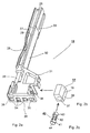
- FIGS. 2a, 2b and 2c An example is shown below using FIGS. 2a, 2b and 2c first embodiment of the invention explained in more detail.
- 2a shows a perspective top view on the head region of a guide rail, Figure 2b, a receiving contact part and FIG. 2c an advantageous, additional one Contact means for insertion in the receiving contact part.
- the guide rail shown in detail in FIG. 2a 15 has a head region 31, on which a rail-shaped Extension area 32 connects. On their tops there is a guide groove 25 for engaging the Edge of a printed circuit board. This can be funnel-shaped Insertion area 26 on the front side 39 of the head area 31 are inserted into the guide groove 25, the is delimited by a left, right groove wall 27, 28.
- Such an embodiment is described in DE 36 24 839.
- Groove walls 27, 28 and groove base also have region 30 an interruption.
- An ESD contact spring can be used here like this e.g.
- extension area 32 into a separate, possibly multipart Extension piece 33 over that to the extension area 32 is attachable.
- This version is e.g. in WO 96/39013.
- At the front 39 of the head area 31 are also located below the lead-in area 26 coding chambers for the engagement of coding pins 34th
- Each guide rail advantageously has at least one holding device for inserting a receiving contact part 17 electrically conductive material.
- This is preferred as trough-shaped receiving chamber 36 designed, and preferably on Head region 31 of the guide rail and in close proximity to Insert side 2 of the rack 1 arranged.
- the receiving contact part is on the one hand on a cross-connection rail contactable with low resistance and on the other hand has one Contact area, which is preferred for contacting one pin-shaped centering contact part on a front element serves.
- the holding device e.g. Have detent springs, which a starting contact part starting from the head region of the guide rail e.g. embrace on the flanks.
- the contact area can preferably be in the form of a receptacle contact part integrated contact cavity his.
- the contact area can preferably be in the form of a receptacle contact part integrated contact cavity his.
- the contact area can be designed differently.
- the receiving chamber 36 also from a region of the end face 39 of the Head area 31 limited. So that a centering contact part in the receiving chamber 36 and in a possibly inserted therein Can dip contact part 17, has the End face 39 additionally a receiving opening 35 for Centering contact part.
- This version has the advantage that when a centering contact part is immersed in the receiving opening 35 achieved at least one centering effect becomes, even if no receiving contact part in the receiving chamber 36 17 should be inserted.
- Figure 2b shows a first embodiment of a receiving contact part 17. This can be symbolized by an arrow in the receiving chamber 36 are inserted.
- This has, for example the shape of a block-shaped contact body 18, the the invisible underside of contact means 38 for low resistance Contacting on a cross-connection rail, in particular a clamping mandrel, and a contact cavity on the end face 37 for entry of a preferably pin-shaped Has centering contact part.
- FIG. 2c shows an advantageous embodiment for an additional Contact means 40 between a receiving contact part and a centering contact part.
- This can be advantageous as a cage spring or barrel spring can be executed, which in the contact cavity 37 of the receiving contact part 17 can be integrated is.
- the cage spring 40 advantageously has a front slotted cylindrical sleeve 41 and a rear slotted, cylindrical sleeve 43, which over after inside bent spring contact blades 42 are connected. This form a narrowed contact channel, which is electrically conductive rests on a centering contact part, which over the front insertion area 44 in the sleeve 41 in the contact means 40 is immersed.
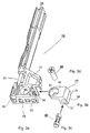
- FIGS. 3a, 3b, 3c and 3d a exemplary second embodiment of the invention explained in more detail.
- 3a shows one corresponding to FIG. 2a perspective top view of the head region of a guide rail
- Figure 3b a receiving contact part
- Figure 3c an advantageous additional, corresponding to FIG. 2c
- Contact means for insertion in the receiving contact part
- figure 3d finally shows an additional connection means for the receiving contact part with a cross-connection rail.
- the receiving contact part 17 shown in Figure 3b has Comparison to the receiving contact part of Figure 2b via an additional Fastening tab 46 on the block-shaped contact body 18.
- This has a passage opening 47 for a fastener 45, which, for example, in FIG a screw is shown.
- the fastener 45 serves for permanent attachment of the receiving contact part 17 on the cross-connection rail.
- a Requirements for a protective contact correspond particularly well electrically low-resistance contact with special high current carrying capacity.
- the head region 31 of the guide rail 15 is designed so that the Fastening tab 46 of one inserted into the receiving trough 36 Receiving contact part 17 on the top 60 of the head area 31 rests and the fastener 45 both through the through opening 47 of the mounting bracket 46 as also through a corresponding through opening 48 in Head area 31 through to an underlying cross-connection rail reaches through.
- This can be a very compact mounting of the guide rail and receiving contact part can be reached on a cross-connection rail.
- FIG. 4 Such an arrangement is in the assembled state in FIG. 4 shown.
- front lower cross-connection rail 5 is the lower guide rails 15 in the range of their preferably widened head area 31 is placed on and preferably via mounting holes 51 with the cross-connection rail 5 locked.
- a receiving contact part 17 is in the way described above in the head region 31 of the guide rail 15 inserted.
- One that serves as a lanyard Screw 45 engages both through the receiving contact part 17th as well as through the underlying head region 31 of the guide rails 15 through and is in one of the mounting holes 51 the cross-connection rail 5 screwed.
- Figure 4 also shows a detail of the front element 13 for the slot 57, which is not included for a better overview an electrical printed circuit board. Their one Long side is with an additional contact spring strip 49 busy.
- the front element 13 contains a front plate 19 electrically conductive material, at the lower end of a lower End piece 21 with a lower lever pull handle 23 and a lower centering contact part 25. This corresponds when placing the front element 13 on the insertion side 2 of the subrack with the receiving contact part 17 that this via the receiving opening 35 into the contact cavity 37 dips.
- Both ground contacting of the Front element 13 and a possibly associated with it PCB assembly, as well as a mechanical centering an insertion process can be effected.
- FIG. 5 shows one in the head region 31 of the guide rail 15 located sectional view through a receiving contact part 17th with an inserted contact means 40.
- the execution corresponds the representations in Figures 3a, 3b, 3c, 3d and 4.
- the guide rail 15 points below the head area 31 at least one engagement knob 52, which in a Engage mounting hole 51 on a cross-connection rail.
- a locking lug 53 available, which for reaching behind an edge of the Cross-connection rail is used.
- Threaded part as a simultaneous fastener for Receiving contact part 17 and head region 31 of the guide rail serving screw 45 shown.
- Figure 6 shows a perspective side view of another Execution of a receiving contact part 17, in which the Contact means 38 on the underside of additional barbs or has cutting edges.
- Figure 7 shows a perspective side view of another embodiment a receiving contact part 17, in which the contact body 18 both the contact cavity 37 and the through opening 47 for a fastener.
- Figures 8a, 8b show perspective top views further embodiments of a guide rail 15 and one Recording contact part 17.
- the representations in Figures 3a, 3b, 3c, 3d and 4 correspond refer to the associated explanations above. additionally but shows the execution of the receiving contact part 17 a contact knife 54 according to the invention in FIG. 8b. in the Example of Figure 8b, this is advantageously in one piece with the fastening tab 46 connected and towards the Guide groove 25 spread on the guide rail. At a other, not shown version, this can also represent separate part, which with mechanical the receiving contact part 17 is connected.
- One of the groove walls of a guide groove is advantageous, in the example of Figures 8a, 9, the left groove wall 27 of the guide groove 25 on the guide rail 15, in a contact knife 54 opposite area 55 in sections from the groove base separated and designed like a bell-shaped leaf spring, that the width of the guide groove 25 in the engagement area of the contact knife 54 is tapered. With this the Edge of a printed circuit board pressed onto the contact knife and e.g. a conductor track located on the printed circuit board grinding contact with the contact knife.
- connection means preferably in the form of a screw be provided, with which both the receiving contact part 17th including contact knife 54, as well as the guide rail 15 especially over the head area 31 with one below horizontal connecting rail mechanically and electrically is conductively connectable.
- FIG 9 shows in Figure 9 is such a connecting screw in the through openings 47 and 48 of the receiving contact part 17 and the guide rail 15 used.
Landscapes
- Engineering & Computer Science (AREA)
- Microelectronics & Electronic Packaging (AREA)
- Mounting Of Printed Circuit Boards And The Like (AREA)
- Details Of Connecting Devices For Male And Female Coupling (AREA)
- Coupling Device And Connection With Printed Circuit (AREA)
- Chain Conveyers (AREA)
Claims (19)
- Système de montage pour cartes imprimées électriques (58, 59) comprenanta) un support de cartes (1) muni d'emplacements de montage (56, 57) pour insérer des cartes imprimées électriques (58, 59), comprenanta1) des rails de liaison transversaux (4, 5 ; 6, 7) opposés en matériau conducteur d'électricité,a2) avec des rails de guidage (14, 15) pour l'insertion des cartes imprimées (58, 59) dans les emplacements de montage (57), lesquels sont montés sur les rails de liaison transversaux (4, 5 ; 6, 7) et présentent un dispositif de maintien (36) pour y loger una3) élément de contact femelle (16, 17) en matériau conducteur d'électricité qui peut être mis en contact à faible impédance avec un rail de liaison transversal (4, 5 ; 6, 7) et présente une zone de contact (37), et comprenantb) des éléments frontaux (12, 13) conducteurs d'électricité qui sont à chaque fois associés à un emplacement de montage (57) et présentent au moins un élément de contact et de centrage (24, 25) en saillie en direction du côté insertion (2) du support de cartes (1), lequel peut être mis en contact électrique à faible impédance et à haute capacité de transport du courant avec la zone de contact (37) de l'élément de contact femelle (17) lors de la mise en place d'un élément frontal (12, 13) sur un emplacement de montage (57).
- Système de montage selon la revendication 1, dans lequel un rail de guidage (14, 15) présente une chambre de réception de préférence en forme d'auge faisant office de dispositif de maintien (36).
- Système de montage selon la revendication 1 ou 2, dans lequel un rail de guidage (14, 15) présente sur un côté frontal (39) dirigé vers le côté insertion (2) du support de cartes (1) un orifice d'accueil (35) pour un élément de contact et de centrage (25) qui débouche dans le dispositif de maintien (36) pour un élément de contact femelle (16, 17).
- Système de montage selon l'une des revendications précédentes, comprenant un moyen de liaison supplémentaire (45), notamment une liaison par vis pour la fixation électrique à faible impédance d'un élément de contact femelle (17) sur un rail de liaison transversal (5).
- Système de montage selon la revendication 4, dans lequel le moyen de liaison (45) réalise également une fixation du rail de guidage (14, 15) sur le rail de liaison transversal (5).
- Système de montage selon la revendication 4 ou 5, dans lequel le rail de guidage (14, 15) présente une ouverture de pénétration (48) qui s'étend jusqu'au rail de liaison transversal (5) pour le moyen de liaison (45) de l'élément de contact femelle (17).
- Système de montage selon la revendication 4, 5 ou 6, dans lequel les éléments de contact femelles (16, 17) présententa) un corps de contact (18) qui présente la zone de contact (37) pour un élément de contact et de centrage (24, 25),b) une éclisse de fixation (46) pour la pénétration du moyen de liaison (45).
- Système de montage selon l'une des revendications précédentes, dans lequel les rails de guidage (14, 15) présentent au moins une zone de tête (31) de préférence élargie qui repose sur un rail de liaison transversal (4, 5 ; 6, 7) et qui est intégrée dans le dispositif de maintien (36) pour un élément de contact femelle (16, 17).
- Système de montage selon la revendication 7, dans lequel les rails de guidage (14, 15) présentent une zone de tête élargie (31) qui repose sur un rail de liaison transversal (4, 5 ; 6, 7) et qui est intégrée dans le dispositif de maintien (36) pour un élément de contact femelle (16, 17) de sorte que l'éclisse de fixation (46) de l'élément de contact femelle (16, 17) repose sur un côté supérieur (60) de la zone de tête (31) et un moyen de liaison (45) traverse l'éclisse de fixation (46) et la zone de tête (31) jusqu'au rail de liaison transversal.
- Système de montage selon l'une des revendications précédentes, comprenant un moyen de contact supplémentaire (40) entre un élément de contact femelle (17) et un élément de contact et de centrage (25), notamment un ressort à cage intégré dans l'élément de contact femelle (17).
- Système de montage selon l'une des revendications précédentes, dans lequel un élément de contact femelle (16, 17) présente en plus une lame de contact (54) qui s'étend jusqu'à une rainure de guidage (25) sur un rail de guidage (15) et entre en contact avec une carte imprimée (59) pour évacuer les potentiels électrostatiques, notamment depuis son élément frontal (13).
- Système de montage pour cartes imprimées électriques (58, 59) comprenanta) un support de cartes (1) muni d'emplacements de montage (56, 57) pour insérer des cartes imprimées électriques (58, 59), comprenanta1) des rails de liaison transversaux (4, 5 ; 6, 7) opposés en matériau conducteur d'électricité,a2) avec des rails de guidage (14, 15) pour l'insertion des cartes imprimées (58, 59) dans les emplacements de montage (57), lesquels sont montés sur les rails de liaison transversaux (4, 5 ; 6, 7), eta3) au moins un élément de contact femelle (16, 17) en matériau conducteur d'électricité qui est associé à un emplacement de montage (56 ; 57) et qui peut être mis en contact à faible impédance avec un rail de liaison transversal (4, 5 ; 6, 7) et présente une zone de contact (37) et une lame de contact (54) qui s'étend dans une rainure de guidage (25) du rail de guidage (15), etb) des éléments frontaux (12, 13) conducteurs d'électricité pour les cartes imprimées (58, 59) qui présentent au moins un élément de contact et de centrage (24, 25) en saillie en direction du côté insertion (2) du support de cartes (1), dans lequel lors de l'insertion de la carte imprimée (59) dans un emplacement de montage (57)b1) l'élément de contact et de centrage (24, 25) peut entrer en contact électrique à faible impédance et à haute capacité de transport du courant avec la zone de contact (37) de l'élément de contact femelle (17) etb2) la lame de contact (54) d'un élément de contact femelle (17) entre en contact avec la carte électrique (59) pour évacuer les potentiels électrostatiques.
- Système de montage selon la revendication 12, dans lequel un rail de guidage (14, 15) présente un dispositif de maintien (36), de préférence une chambre de réception en forme d'auge pour y loger un élément de contact femelle (16, 17).
- Système de montage selon la revendication 12 ou 13, comprenant un moyen de liaison supplémentaire (45), notamment une liaison par vis pour la fixation électrique à faible impédance d'un élément de contact femelle (17) sur un rail de liaison transversal (5).
- Système de montage selon la revendication 14, dans lequel le moyen de liaison (45) réalise également une fixation du rail de guidage (14, 15) sur le rail de liaison transversal (5).
- Système de montage selon la revendication 14 ou 15, dans lequel les éléments de contact femelles (16, 17) présententa) un corps de contact (18) qui présente la zone de contact (37) pour un élément de contact et de centrage (24, 25), etb) une éclisse de fixation (46) pour la pénétration du moyen de liaison (45).
- Système de montage selon la revendication 16, dans lequel la lame de contact (54) est reliée d'une seule pièce avec l'éclisse de fixation (46) d'un élément de contact femelle (16, 17).
- Système de montage selon l'une des revendications 12 à 17, dans lequel la rainure de guidage (25) sur un rail de guidage (15) est délimitée par des parois de rainure (27, 28) et une paroi de rainure (27) à l'opposé de la lame de contact (54) est séparée par sections du fond de la rainure de guidage (25) et configurée sous la forme d'une lame de ressort en forme de courbe en cloche de sorte que la largeur de la rainure de guidage (25) se rétrécit dans la zone de la lame de contact (54).
- Système de montage selon l'une des revendications précédentes, comprenant des rails de guidage (14, 15) en matériau non conducteur d'électricité.
Applications Claiming Priority (3)
| Application Number | Priority Date | Filing Date | Title |
|---|---|---|---|
| DE19851516 | 1998-11-09 | ||
| DE19851516 | 1998-11-09 | ||
| PCT/DE1999/003572 WO2000028799A1 (fr) | 1998-11-09 | 1999-11-09 | Systeme de montage pour cartes imprimees electriques avec contacts de centrage sur des elements frontaux et contacts de reception distincts en particulier avec des lames de contact dans le chassis |
Publications (2)
| Publication Number | Publication Date |
|---|---|
| EP1131987A1 EP1131987A1 (fr) | 2001-09-12 |
| EP1131987B1 true EP1131987B1 (fr) | 2004-10-13 |
Family
ID=7887121
Family Applications (1)
| Application Number | Title | Priority Date | Filing Date |
|---|---|---|---|
| EP99960877A Expired - Lifetime EP1131987B1 (fr) | 1998-11-09 | 1999-11-09 | Systeme de montage pour cartes imprimees electriques avec contacts de centrage sur des elements frontaux et contacts de reception distincts en particulier avec des lames de contact dans le chassis |
Country Status (7)
| Country | Link |
|---|---|
| US (1) | US6560120B2 (fr) |
| EP (1) | EP1131987B1 (fr) |
| JP (1) | JP4263851B2 (fr) |
| CN (1) | CN1258310C (fr) |
| AT (1) | ATE279852T1 (fr) |
| DE (1) | DE59910860D1 (fr) |
| WO (1) | WO2000028799A1 (fr) |
Families Citing this family (13)
| Publication number | Priority date | Publication date | Assignee | Title |
|---|---|---|---|---|
| DE20014198U1 (de) * | 2000-08-17 | 2001-10-04 | Siemens AG, 80333 München | Frontsystem für eine Flachbaugruppe mit integriertem elektrischen Anzeigeelement sowie Hebelziehgriff mit einem Endstück für ein Frontsystem |
| US20050011672A1 (en) * | 2003-07-17 | 2005-01-20 | Alawani Ashish D. | Overmolded MCM with increased surface mount component reliability |
| CN2681395Y (zh) * | 2003-12-16 | 2005-02-23 | 鸿富锦精密工业(深圳)有限公司 | 插件箱防误插结构 |
| DE102004054310B4 (de) * | 2004-11-09 | 2006-11-16 | Rittal Res Electronic Systems Gmbh & Co. Kg | Elektrische Verbindung eines Kontaktstiftes mit einem Blechbauteil |
| DE102004054338B4 (de) * | 2004-11-09 | 2013-02-21 | Rittal Res Electronic Systems Gmbh & Co. Kg | Kopf- oder Bodenteil eines Baugruppenträgers |
| DE102005056380B8 (de) * | 2005-11-24 | 2008-08-28 | Rittal Res Electronic Systems Gmbh & Co. Kg | Kopf- oder Bodenteil eines Baugruppenträgers |
| US20070221591A1 (en) * | 2006-03-24 | 2007-09-27 | Yang-Yuan Hsu | Wedged sliding trough structure |
| US20110037357A1 (en) * | 2009-08-12 | 2011-02-17 | Li-Fu Chiang | Guideway device for server casings |
| CN102076172B (zh) * | 2011-01-04 | 2012-05-23 | 江苏传艺科技有限公司 | 一种用于柔性线路板自动组配的装置 |
| CN202310409U (zh) * | 2011-10-26 | 2012-07-04 | 中兴通讯股份有限公司 | 一种组合导轨 |
| CN204795997U (zh) * | 2015-07-15 | 2015-11-18 | 中兴通讯股份有限公司 | 一种插箱拼装导轨结构 |
| CN114071926B (zh) * | 2021-11-27 | 2022-07-08 | 深圳市天技电子技术有限公司 | 一种便于卡接不易晃动的电功率模块安装结构 |
| CN116190984B (zh) * | 2023-04-06 | 2025-08-01 | 广东博纬通信科技有限公司 | 一种天线控制器的固定安装及接地装置 |
Family Cites Families (12)
| Publication number | Priority date | Publication date | Assignee | Title |
|---|---|---|---|---|
| US3696936A (en) * | 1970-12-15 | 1972-10-10 | Electro Space Fabricators Inc | Printed circuit card rack |
| DE3624839A1 (de) | 1986-07-23 | 1988-01-28 | Siemens Ag | Fuehrungsschiene |
| DE3624883A1 (de) * | 1986-07-23 | 1988-01-28 | Siemens Ag | Kontaktfeder |
| DE3634462A1 (de) | 1986-10-09 | 1988-04-21 | Licentia Gmbh | Mit profilschienen eines baugruppentraegers verbindbare halteschiene |
| GB9126235D0 (en) * | 1991-12-11 | 1992-02-12 | Bicc Plc | Enclosure for circuit boards |
| EP0579859B1 (fr) | 1992-07-24 | 1996-02-28 | Siemens Aktiengesellschaft | Plaque de circuit imprimé avec des tiges de guidage pour l'insérer en position correcte dans un rack électronique |
| DE29508853U1 (de) | 1995-05-29 | 1996-07-04 | Siemens AG, 80333 München | Universelle, modulare Führungsschiene für Leiterplatten |
| DE29509185U1 (de) | 1995-06-02 | 1996-07-04 | Siemens AG, 80333 München | Führungsschiene mit integrierter Kontaktfeder zur Führung, Kontaktierung und Halterung einer Flachbaugruppe in einem Baugruppenträger |
| DE29509603U1 (de) | 1995-06-12 | 1996-07-11 | Siemens AG, 80333 München | Frontsystem für eine Flachbaugruppe mit Aktiv-Passiv-Schaltung |
| DE29610694U1 (de) | 1996-06-18 | 1997-07-17 | Siemens AG, 80333 München | Baugruppenträger mit Mitteln zur Ableitung elektrostatischer Spannungen bei einsteckbaren Baugruppen |
| DE19755018C1 (de) * | 1997-12-11 | 1999-02-04 | Schroff Gmbh | Kartensicherung zum Sichern einer Leiterkarte |
| DE19807555C1 (de) * | 1998-02-23 | 1999-12-02 | Siemens Ag | Aufbausystem zum Einschub von elektrischen Flachbaugruppen |
-
1999
- 1999-11-09 EP EP99960877A patent/EP1131987B1/fr not_active Expired - Lifetime
- 1999-11-09 AT AT99960877T patent/ATE279852T1/de not_active IP Right Cessation
- 1999-11-09 WO PCT/DE1999/003572 patent/WO2000028799A1/fr not_active Ceased
- 1999-11-09 CN CNB998141216A patent/CN1258310C/zh not_active Expired - Fee Related
- 1999-11-09 DE DE1999510860 patent/DE59910860D1/de not_active Expired - Lifetime
- 1999-11-09 JP JP2000581867A patent/JP4263851B2/ja not_active Expired - Fee Related
-
2001
- 2001-05-09 US US09/851,381 patent/US6560120B2/en not_active Expired - Fee Related
Also Published As
| Publication number | Publication date |
|---|---|
| US20020006034A1 (en) | 2002-01-17 |
| US6560120B2 (en) | 2003-05-06 |
| WO2000028799A1 (fr) | 2000-05-18 |
| CN1335046A (zh) | 2002-02-06 |
| DE59910860D1 (de) | 2004-11-18 |
| JP2002529939A (ja) | 2002-09-10 |
| JP4263851B2 (ja) | 2009-05-13 |
| ATE279852T1 (de) | 2004-10-15 |
| EP1131987A1 (fr) | 2001-09-12 |
| CN1258310C (zh) | 2006-05-31 |
Similar Documents
| Publication | Publication Date | Title |
|---|---|---|
| DE4241876C2 (de) | Einschub-/Entnahmevorrichtung für Schaltungsplatinen | |
| EP3446381B1 (fr) | Agencement permettant la connexion sans risque de contact d'un système de rails collecteurs de courant | |
| EP1131987B1 (fr) | Systeme de montage pour cartes imprimees electriques avec contacts de centrage sur des elements frontaux et contacts de reception distincts en particulier avec des lames de contact dans le chassis | |
| DE3322856A1 (de) | Frontsystem fuer in baugruppentraeger einschiebbare steckbaugruppen und rahmenartige baugruppentraeger zu deren aufnahme | |
| DE19748530B9 (de) | Modulares Automatisierungsgerät und Baugruppe eines modularen Automatisierungsgerätes | |
| EP1057385B1 (fr) | Systeme de ratelier pour l'insertion d'ensembles plats electriques | |
| EP0129883B1 (fr) | Système frontal pour des plaquettes de composants insérables dans un bâti et un bâti pour recevoir celles-ci | |
| EP0133152A1 (fr) | Dispositif pour la connexion de conducteurs auxiliaires à un appareil de commutation ou une combinaison d'appareils de commutation | |
| EP0926791B1 (fr) | Adaptateur avec un boîtier de base pour un jeu de barres omnibus avec plusieurs barres de distribution de courant | |
| DE102006031129B4 (de) | Gerätesystem mit auf einer Tragschiene montierten elektrischen Gerätemodulen und in der Tragschine angeordneter BUS-Leitung | |
| EP0180056B1 (fr) | Câblage de panneau arrière pour unités électriques | |
| DE102012203554B4 (de) | Sammelschienenabgreifklemme | |
| DE3634462C2 (fr) | ||
| DE102024110871B3 (de) | Elektrische Installation mit einer Anordnung für die berührungssichere Kontaktierung mehrerer Stromsammelschienen mit Kabeldurchführung | |
| DE19507724C1 (de) | Vorrichtung zum Kodieren des Einschubplatzes einer Steckbaugruppe in einem Baugruppenträger | |
| EP1867021B9 (fr) | Installation de distribution electrique et module de base pour installation de distribution electrique | |
| DE19610037C2 (de) | Baugruppenträger | |
| EP0621668B1 (fr) | Protection contre les contacts accidentels pour des barres omnibus | |
| DE29819968U1 (de) | Aufbausystem für elektrische Flachbaugruppen mit Zentrierkontaktteilen an Frontelementen und separaten Aufnahmekontaktteilen insbesondere mit Kontaktmessern im Baugruppenträger | |
| EP0589307B1 (fr) | Support pour appareils comportant un rail avec fixation mécanique et contact électrique integral | |
| AT409047B (de) | Vorrichtung zur erdung einer modular aufgebauten gehäuseeinheit | |
| DE102023003274A1 (de) | Verbindungsvorrichtung | |
| DE2919394A1 (de) | Montagevorrichtung fuer eine oder mehrere netzueberwachungseinrichtungen | |
| DE3529105A1 (de) | Geraeteeinsatz der nachrichtentechnik | |
| DE29803150U1 (de) | Aufbausystem zum Einschub von elektrischen Flachbaugruppen |
Legal Events
| Date | Code | Title | Description |
|---|---|---|---|
| PUAI | Public reference made under article 153(3) epc to a published international application that has entered the european phase |
Free format text: ORIGINAL CODE: 0009012 |
|
| 17P | Request for examination filed |
Effective date: 20010611 |
|
| AK | Designated contracting states |
Kind code of ref document: A1 Designated state(s): AT BE CH CY DE DK ES FI FR GB GR IE IT LI LU MC NL PT SE |
|
| GRAP | Despatch of communication of intention to grant a patent |
Free format text: ORIGINAL CODE: EPIDOSNIGR1 |
|
| RBV | Designated contracting states (corrected) |
Designated state(s): AT CH DE ES FR GB IT LI NL SE |
|
| GRAS | Grant fee paid |
Free format text: ORIGINAL CODE: EPIDOSNIGR3 |
|
| GRAA | (expected) grant |
Free format text: ORIGINAL CODE: 0009210 |
|
| AK | Designated contracting states |
Kind code of ref document: B1 Designated state(s): AT CH DE ES FR GB IT LI NL SE |
|
| PG25 | Lapsed in a contracting state [announced via postgrant information from national office to epo] |
Ref country code: SE Free format text: LAPSE BECAUSE OF FAILURE TO SUBMIT A TRANSLATION OF THE DESCRIPTION OR TO PAY THE FEE WITHIN THE PRESCRIBED TIME-LIMIT Effective date: 20041013 Ref country code: NL Free format text: LAPSE BECAUSE OF FAILURE TO SUBMIT A TRANSLATION OF THE DESCRIPTION OR TO PAY THE FEE WITHIN THE PRESCRIBED TIME-LIMIT Effective date: 20041013 Ref country code: IT Free format text: LAPSE BECAUSE OF FAILURE TO SUBMIT A TRANSLATION OF THE DESCRIPTION OR TO PAY THE FEE WITHIN THE PRESCRIBED TIME-LIMIT;WARNING: LAPSES OF ITALIAN PATENTS WITH EFFECTIVE DATE BEFORE 2007 MAY HAVE OCCURRED AT ANY TIME BEFORE 2007. THE CORRECT EFFECTIVE DATE MAY BE DIFFERENT FROM THE ONE RECORDED. Effective date: 20041013 Ref country code: GB Free format text: LAPSE BECAUSE OF FAILURE TO SUBMIT A TRANSLATION OF THE DESCRIPTION OR TO PAY THE FEE WITHIN THE PRESCRIBED TIME-LIMIT Effective date: 20041013 Ref country code: FR Free format text: LAPSE BECAUSE OF FAILURE TO SUBMIT A TRANSLATION OF THE DESCRIPTION OR TO PAY THE FEE WITHIN THE PRESCRIBED TIME-LIMIT Effective date: 20041013 Ref country code: ES Free format text: LAPSE BECAUSE OF FAILURE TO SUBMIT A TRANSLATION OF THE DESCRIPTION OR TO PAY THE FEE WITHIN THE PRESCRIBED TIME-LIMIT Effective date: 20041013 |
|
| REG | Reference to a national code |
Ref country code: GB Ref legal event code: FG4D Free format text: NOT ENGLISH |
|
| REG | Reference to a national code |
Ref country code: CH Ref legal event code: EP |
|
| PG25 | Lapsed in a contracting state [announced via postgrant information from national office to epo] |
Ref country code: AT Free format text: LAPSE BECAUSE OF NON-PAYMENT OF DUE FEES Effective date: 20041109 |
|
| REG | Reference to a national code |
Ref country code: IE Ref legal event code: FG4D Free format text: GERMAN |
|
| REF | Corresponds to: |
Ref document number: 59910860 Country of ref document: DE Date of ref document: 20041118 Kind code of ref document: P |
|
| PG25 | Lapsed in a contracting state [announced via postgrant information from national office to epo] |
Ref country code: LI Free format text: LAPSE BECAUSE OF NON-PAYMENT OF DUE FEES Effective date: 20041130 Ref country code: CH Free format text: LAPSE BECAUSE OF NON-PAYMENT OF DUE FEES Effective date: 20041130 |
|
| NLV1 | Nl: lapsed or annulled due to failure to fulfill the requirements of art. 29p and 29m of the patents act | ||
| GBV | Gb: ep patent (uk) treated as always having been void in accordance with gb section 77(7)/1977 [no translation filed] |
Effective date: 20041013 |
|
| REG | Reference to a national code |
Ref country code: IE Ref legal event code: FD4D |
|
| REG | Reference to a national code |
Ref country code: CH Ref legal event code: PL |
|
| PLBE | No opposition filed within time limit |
Free format text: ORIGINAL CODE: 0009261 |
|
| STAA | Information on the status of an ep patent application or granted ep patent |
Free format text: STATUS: NO OPPOSITION FILED WITHIN TIME LIMIT |
|
| 26N | No opposition filed |
Effective date: 20050714 |
|
| EN | Fr: translation not filed | ||
| PGFP | Annual fee paid to national office [announced via postgrant information from national office to epo] |
Ref country code: DE Payment date: 20091120 Year of fee payment: 11 |
|
| PG25 | Lapsed in a contracting state [announced via postgrant information from national office to epo] |
Ref country code: DE Free format text: LAPSE BECAUSE OF NON-PAYMENT OF DUE FEES Effective date: 20110531 |
|
| REG | Reference to a national code |
Ref country code: DE Ref legal event code: R119 Ref document number: 59910860 Country of ref document: DE Effective date: 20110601 Ref country code: DE Ref legal event code: R119 Ref document number: 59910860 Country of ref document: DE Effective date: 20110531 |