EP1132037A2 - Reinigungsgerät zur Bodenreinigung - Google Patents
Reinigungsgerät zur Bodenreinigung Download PDFInfo
- Publication number
- EP1132037A2 EP1132037A2 EP01102449A EP01102449A EP1132037A2 EP 1132037 A2 EP1132037 A2 EP 1132037A2 EP 01102449 A EP01102449 A EP 01102449A EP 01102449 A EP01102449 A EP 01102449A EP 1132037 A2 EP1132037 A2 EP 1132037A2
- Authority
- EP
- European Patent Office
- Prior art keywords
- cooling air
- cleaning device
- electric motor
- flow
- suction
- Prior art date
- Legal status (The legal status is an assumption and is not a legal conclusion. Google has not performed a legal analysis and makes no representation as to the accuracy of the status listed.)
- Granted
Links
- 238000004140 cleaning Methods 0.000 title claims abstract description 57
- 238000001816 cooling Methods 0.000 claims abstract description 83
- 239000007788 liquid Substances 0.000 claims description 15
- 238000005192 partition Methods 0.000 claims description 10
- 239000003599 detergent Substances 0.000 claims description 6
- 238000003860 storage Methods 0.000 claims description 5
- 239000012459 cleaning agent Substances 0.000 claims description 4
- 238000012549 training Methods 0.000 claims description 2
- 238000007599 discharging Methods 0.000 claims 2
- 239000000463 material Substances 0.000 claims 1
- 238000000926 separation method Methods 0.000 claims 1
- XLYOFNOQVPJJNP-UHFFFAOYSA-N water Substances O XLYOFNOQVPJJNP-UHFFFAOYSA-N 0.000 description 7
- 230000002349 favourable effect Effects 0.000 description 3
- 230000005484 gravity Effects 0.000 description 3
- 238000013461 design Methods 0.000 description 2
- 230000000694 effects Effects 0.000 description 2
- 238000002347 injection Methods 0.000 description 2
- 239000007924 injection Substances 0.000 description 2
- 238000005304 joining Methods 0.000 description 2
- 239000000203 mixture Substances 0.000 description 2
- 230000015572 biosynthetic process Effects 0.000 description 1
- 238000004891 communication Methods 0.000 description 1
- 238000000605 extraction Methods 0.000 description 1
- 238000009434 installation Methods 0.000 description 1
- 238000004519 manufacturing process Methods 0.000 description 1
- 238000013021 overheating Methods 0.000 description 1
- 230000000149 penetrating effect Effects 0.000 description 1
- 230000035939 shock Effects 0.000 description 1
- 239000007921 spray Substances 0.000 description 1
- 238000012546 transfer Methods 0.000 description 1
Images


Classifications
-
- A—HUMAN NECESSITIES
- A47—FURNITURE; DOMESTIC ARTICLES OR APPLIANCES; COFFEE MILLS; SPICE MILLS; SUCTION CLEANERS IN GENERAL
- A47L—DOMESTIC WASHING OR CLEANING; SUCTION CLEANERS IN GENERAL
- A47L11/00—Machines for cleaning floors, carpets, furniture, walls, or wall coverings
- A47L11/40—Parts or details of machines not provided for in groups A47L11/02 - A47L11/38, or not restricted to one of these groups, e.g. handles, arrangements of switches, skirts, buffers, levers
-
- A—HUMAN NECESSITIES
- A47—FURNITURE; DOMESTIC ARTICLES OR APPLIANCES; COFFEE MILLS; SPICE MILLS; SUCTION CLEANERS IN GENERAL
- A47L—DOMESTIC WASHING OR CLEANING; SUCTION CLEANERS IN GENERAL
- A47L9/00—Details or accessories of suction cleaners, e.g. mechanical means for controlling the suction or for effecting pulsating action; Storing devices specially adapted to suction cleaners or parts thereof; Carrying-vehicles specially adapted for suction cleaners
- A47L9/22—Mountings for motor fan assemblies
Definitions
- the invention relates to a cleaning device for floor cleaning with a storage container for a detergent, a cleaning head connected to the storage container to apply liquid or vapor Detergent on a floor surface to be cleaned and with one with the cleaning head via a suction line connected suction unit to achieve a suction air flow for picking up and transferring dirt and applied detergent in a collection container, the suction unit and a drive this air-cooled electric motor in two half shells having housing are arranged and that Housing suction air outlet openings to discharge the from Suction unit sucked suction air and cooling air inlet and -Outlet openings for receiving and dispensing Cooling air for cooling the electric motor.
- Such cleaning devices come in particular as so-called Spray extraction devices for use where a liquid or vapor detergent applied the floor surface to be cleaned and the cleaning agent along with the loosened dirt the suction line is suctioned off again and placed in a collection container is transferred.
- the suction air flow required for this is generated by means of a suction unit, that is powered by an air-cooled electric motor becomes.
- the object of the present invention is a cleaning device of the type mentioned in the invention to further develop such that it can be manufactured more cost-effectively and in particular can be installed in a shorter time is.
- This task is the generic type in a cleaning device Art solved according to the invention in that the electric motor and the suction unit in one in the Housing insert is held, the interior of the housing in a the suction unit with the Suction air chamber connecting suction air outlet openings and one the electric motor with the cooling air inlet and - Cooling air chamber connecting outlet openings divided.
- the cleaning device according to the invention stands out through a particularly simple assembly, because the Electric motor and the suction unit can be in a first Installation step independent of the housing on the holding insert be attached. Then the holding insert can insert into one of the housing shells, and the second half shell can then be placed on the holding insert be put on.
- the holding insert divides the interior of the housing into a suction air chamber and a separate cooling air chamber. The suction air drawn in by the suction unit enters the suction air chamber while cooling cooling air of the electric motor gets into the cooling air chamber. This can be avoided be that droplets of liquid carried along with the suction air captured by the cooling air and in the area of the electric motor can be transferred.
- the Cleaning device according to the invention is accordingly distinguished through an easy assembly, whereby at the same time, high operational reliability is achieved.
- the electric motor and that Suction unit defining a longitudinal axis of the housing are arranged axially one behind the other and the holding insert an essentially transverse to the longitudinal axis, separating the suction air chamber from the cooling air chamber Partition forms.
- Such a configuration enables inexpensive production in particular the housing half-shells, which are preferably plastic injection molded parts are manufactured. This can by designing the holding insert with a Partition a structurally simple injection mold for Use come so that the cleaning device through low tool costs.
- flow elements in the cooling air chamber are arranged to form one of the cooling air inlet openings via the electric motor the cooling air flow leading the cooling air outlet openings.
- the flow elements form a positive guide for the cooling air. This can make an immediate Flow connection between the cooling air inlet openings and the cooling air outlet openings without intermediate connection of the electric motor can be avoided.
- a particularly effective cooling of the electric motor can be achieved in that the flow elements Guide the cooling air along the electric motor.
- the holding insert preferably surrounds the electric motor in the circumferential direction and forms one in the longitudinal direction leading along the outside of the electric motor Cooling channel from the rear, the suction unit opposite end with the cooling air inlet openings in Flow connection is established.
- the holding insert is an electric motor surrounding sleeve forms in the circumferential direction in two diametrically opposed areas lies directly on the electric motor, while it otherwise runs at a distance from the electric motor and between the sleeve wall and the electric motor two diametrically opposing cooling channels through which the Cooling air can be passed through.
- a flow labyrinth is arranged with baffle walls to redirect the cooling air and to separate droplets of liquid carried with the cooling air.
- the flow labyrinth preferably comprises approximately guide walls arranged parallel to each other.
- the cooling air is led around the guide walls and changes its flow direction several times, see above that possibly entrained liquid droplets due to their inertia deposited on the guide walls become.
- At least two guide walls provided in the essentially aligned transversely to the longitudinal direction of the housing are, with a first guide wall on the holding element and a second guide wall on a half shell the housing is held.
- a first guide wall on the holding element and a second guide wall on a half shell the housing is held.
- two in one piece with the holding insert connected guide walls one piece with one Housing half-shell connected guide wall between them take up.
- the preferably designed as a one-piece plastic body Holding insert can, for example, as a staged Hollow cylinders can be designed with a cleaning head facing front area of the suction unit records, and one facing away from the cleaning head rear area that houses the electric motor where several of the hollow cylinder in the radial direction Ribs protrude to separate the suction air chamber from the Cooling air chamber and for the formation of flow elements for the cooling air flow. It is special here favorable if the stepped hollow cylinder in Distance to the housing half-shells is positioned, whereby the risk of damage to the suction unit or the electric motor is reduced by mechanical shocks becomes.
- the attachment of the holding insert can preferably done such that the two half-shells fasteners have, which receive the holding insert.
- the two half-shells can be one, for example clamp surrounding the holding insert in the circumferential direction train the holding insert within the housing fix.
- a particularly inexpensive assembly can be achieved that the half shells and the holding insert releasable by means of grooves and holding ribs that can be inserted into these are interconnectable.
- the half-shells on their the holding insert have receiving grooves on the inside, in which the holding insert by means of corresponding Holding ribs can be used.
- the holding insert and the Half shells are non-rotatably connected.
- the housing and / or the holding insert is asymmetrical with respect to a rotation are formed around the longitudinal axis of the housing.
- the cooling air chamber over at least one passage connected to the suction air chamber is. This gives the opportunity in the cooling air chamber splashed water directly into the To transfer suction air chamber in which a strong suction air flow prevails so that the liquid droplets via the suction air outlet openings from the housing be driven out. It is advantageous if the Passage based on the position of use of the cleaning device arranged below the cooling air inlet openings is so that penetrating through these inlet openings Droplets of liquid under the action of Gravity flow towards the culvert and be transferred via this into the suction air chamber.
- the passage arranged on the inside of a housing half-shell is, for example in a fixing insert holding the Receiving groove is formed.
- connection of the two half-shells is preferably made by means of a tongue and groove connection.
- the groove in its adjacent to the holding insert Area includes two different height groove walls, the take up the corresponding spring between them.
- the higher groove wall forms a guide for the Spring so that the two housing shells on simple Way can be put together.
- the tongue and groove have mutually assigned openings, by means of which it can be ensured that in the Splash water that has penetrated the groove is led out of the groove can be when the cleaning device is in use taken and here its facing away from the cleaning head End is raised so that the penetrated into the groove Splashing water due to the effect of gravity runs out of the groove through the openings.
- the groove in the area of Breakthrough of the tongue between the two groove walls connecting preferably transverse to the longitudinal direction of the groove aligned connecting wall includes.
- the assembly of the cleaning device according to the invention can be simplified by setting the of the holding insert within the housing on the half-shells provided fasteners designed in this way are that when joining the two half shells first the fasteners with the Activate the holding insert before the housing half-shells via the tongue and groove connection with each other are connected.
- the assembly can then be done in this way done that first the holding insert in the first Housing half-shell is used, and that then the second housing half-shell is placed, whereby the second housing half-shell first with the holding insert and then only the tongue and groove connection will be produced.
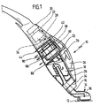
- FIG. 10 In the drawing is a total with the reference number 10 occupied cleaning device for floor cleaning shown.
- This is designed as a stick device includes a cleaning head engaging a bottom surface 12 14, which has a suction line 16 with a Collection container 18 is in flow connection.
- the collecting container in turn stands over a suction nozzle 20 with a suction unit 22 in flow connection.
- the cleaning device 10 is in its use position in FIG shown, in which the suction line 16th is aligned obliquely to the bottom surface 12.
- the collecting container 18 carries one on its top Storage container 24 for a cleaning agent, for example Water.
- a filter unit connects to the reservoir 24 26 on, via a connecting line 28 with a known per se and therefore only in the drawing shown schematically in dashed lines
- Vibrating piston pump 30 is connected to the a water heater 32 connects to generate one Liquid-vapor mixture.
- This liquid-vapor mixture stands with an outlet line 34 with a Nozzle 36 of the cleaning head 14 in flow connection, so that liquid and vapor detergent can be sprayed onto the floor surface 12.
- the sprayed cleaning liquid is then together with the loosened dirt from the bottom surface 12 again recorded and via the suction line 16 in the collecting container 18 transferred.
- suction air flow required for this is caused by the suction unit 22, which is driven by an electric motor 38 the drive shaft of the suction unit 22 attached is, so that electric motor 38 and suction unit 22 immediately are arranged one behind the other and a longitudinal axis Define 40 of the cleaning device 10.
- the electric motor 38 On its back facing away from the suction unit 22 the electric motor 38 carries a fan 42 with its Help a cooling air flow described below can be generated for cooling the electric motor 38.
- the suction unit 22 and the electric motor 38 with the Fans 42 are arranged in a housing 44 which in Figures 2 to 5 is shown enlarged.
- the housing 44 is a first of a second housing half-shell 46 and 48 formed under training a tongue and groove connection 50 on top of each other are attachable.
- the first housing half-shell forms 46 a U-shaped groove 52 with a groove outer wall 54 and a groove inner wall 56, the one between them Take up spring 58, which is integral with the second housing half-shell 48 is connected.
- the groove outer wall 54 is formed higher than the groove inner wall 56, so that the spring 58 when joining the two housing shells 46 and 48 first on the groove outer wall 54 can be created, which is a guide trained for the spring 58.
- FIGS. 2 and 6 have the groove 52 and the tongue 58 assigned to each other Openings 60 and 62 respectively, in the area of Opening 62 of the spring 58 over the groove outer wall 54 a connecting wall aligned transversely to the longitudinal axis 40 64 is connected to the groove inner wall 56.
- the housing 44 receives a holding insert 66 on which the suction unit 22 and the electric motor 38 with fan 42 are set.
- the holding insert 66 is essentially designed in the form of a stepped hollow cylinder with a cleaning head 14 facing front cylinder area 68 to which a step 70 a rear cylinder area 72 connects.
- the front cylinder area 68 surrounds the suction unit 22 in the circumferential direction, while the rear cylinder area 72 surrounds the electric motor in the circumferential direction, wherein this with its fan 42 over the rear, the Suction unit 22 opposite end of the rear cylinder area 72 survives.
- the bracket of the electric motor 38 in the rear cylinder area 72 takes place over two diametrically opposite one another Jaws 74, 76 that are immediate apply to the outside of the electric motor 38 and a first and one in the circumferential direction form second cooling channel 78 and 80, respectively, in the radial Direction on the one hand by the electric motor 38 and on the other hand through the rear cylinder area 72 of the holding insert 66 can be limited.
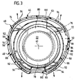
- the holding insert 66 has a radial protruding partition 82 on that with their free End region 84 in one on the inside of the housing half-shells 46 and 48 provided in the circumferential direction extending receiving groove 86 is immersed.
- the Partition 82 turns the interior of housing 44 into a the suction unit 22 associated suction air chamber 88 and a cooling air chamber 90 associated with the electric motor 38 divided.
- the two chambers 88 and 90 are only via passages 92 provided in the receiving groove 86 connected to each other, however, the passages 92 are so narrow that the air currents, which is under the action of the suction unit 22 and the fan 42 in the two chambers 88 and 90 train, not influence each other.
- the housing shells 46 and 48 have in the area of Suction air chamber 88 slot-shaped outlet openings 94 for the suction air sucked in by the suction unit 22.
- the height of the cooling air chamber 90 are in the second housing half-shell 48 also slot-shaped cooling air inlet openings 96 and slot-shaped cooling air outlet openings 98 molded. Between the entry openings 96 and the outlet openings 98 runs a transverse to partition 82 from the step 70 outgoing and down to approximately the height of the fan 42 extending longitudinal wall 100 against which on the Cooling air inlet openings 96 facing side in one piece one the free ends of the longitudinal wall 100 in the circumferential direction interconnecting rear wall 102 connects.
- the rear wall 102 has a central one Through opening 105 on that from the free end of the electric motor 38 is penetrated.
- the rear one Cylinder region 72 of the holding insert 66 in its Rear wall 102 immediately adjacent area itself extending circumferentially along the rear wall 102 Opening 111, which creates a flow connection between the supply air area 107 and the first and second cooling channels 78 and 80, respectively.
- a radially outward molded rear flow guide wall 117, the as well as the front flow guide wall 113 parallel is aligned with the partition 82 and the rear wall 102.
- the front flow guide wall 113 forms in combination with the wall of the rear cylinder area 72, the rear flow guide wall 117 and the rear wall 102 Flow labyrinth for the cooling air inlet openings 96 flowing into the supply air area 107 Cooling air.
- each as Flow guide elements act, the cooling air is multiple deflected, possibly entrained liquid droplets because of their inertia on the walls hit and deposit there.
- the one under the effect of the fan 42 via the opening 111 from the supply air area 107 entering the cooling channels 78 and 80 Cooling air therefore no longer has any liquid droplets on, affected by the function of the electric motor 38 could be.
- the cooling air flows along the outside of the electric motor 38 through the cooling channels 78 and 80, then enters the interior at level 70 of the electric motor 38 and is then driven by the fan 42 through the electric motor 38 into the exhaust air area 109 sucked so that the cooling air is then over the Cooling air outlet openings 98 the housing 44 again can leave.
- the suction unit is used to assemble the cleaning device 10 22 with flanged electric motor 38 and fan 42 axially inserted into the holding insert 66. Subsequently if this is inserted into the housing half-shell 46, and then the housing shell 48 can be put on become.
- the assembly of the suction unit 22 and the Electric motor 38 with fan 42 is thus designed very easy.
- the definition of the holding insert 66 over the partition 82, the longitudinal wall 100 and the rear wall 102 in the associated receiving grooves 86, 101 and 103 of the housing shells 46 and 48 a reliable non-rotatable fixation of the suction unit 22 and the electric motor 38 result, at the same time a division of the interior of the housing into the suction air chambers 88 and the cooling air chamber 90 ensured becomes.
Landscapes
- Engineering & Computer Science (AREA)
- Mechanical Engineering (AREA)
- Nozzles For Electric Vacuum Cleaners (AREA)
- Pinball Game Machines (AREA)
- Vehicle Cleaning, Maintenance, Repair, Refitting, And Outriggers (AREA)
- Dental Tools And Instruments Or Auxiliary Dental Instruments (AREA)
- Cleaning In General (AREA)
Abstract
Description
- Fig. 1:
- eine teilweise aufgetrennte Seitenansicht eines Reinigungsgerätes mit einem motorisch angetriebenen Saugaggregat;
- Fig. 2:
- eine teilweise aufgetrennte Draufsicht auf das Reinigungsgerät im Bereich des Saugaggregates;
- Fig. 3:
- eine Schnittansicht längs der Linie 3-3 in Figur 2;
- Fig. 4:
- eine Schnittansicht längs der Linie 4-4 in Figur 2;
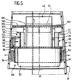
- Fig. 5:
- eine Schnittansicht längs der Linie 5-5 in Figur 2;
- Fig. 6:
- eine Schnittansicht längs der Linie 6-6 in Figur 2.
Claims (21)
- Reinigungsgerät zur Bodenreinigung mit einem Vorratsbehälter für ein Reinigungsmittel, einem mit dem Vorratsbehälter verbundenen Reinigungskopf zum Aufbringen flüssigen oder dampfförmigen Reinigungsmittels auf eine zu reinigende Bodenfläche und mit einem mit dem Reinigungskopf über eine Saugleitung verbundenen Saugaggregat zur Erzielung einer Saugluftströmung zur Aufnahme und Überführung von Schmutz und aufgebrachtem Reinigungsmittel in einen Sammelbehälter, wobei das Saugaggregat und ein dieses antreibender luftgekühlter Elektromotor in einem zwei Halbschalen aufweisenden Gehäuse angeordnet sind und das Gehäuse Saugluftaustrittsöffnungen zum Abgeben der angesaugten Saugluft umfaßt sowie Kühllufteintritts- und -austrittsöffnungen zum Aufnehmen und Abgeben von Kühlluft zur Kühlung des Elektromotors, dadurch gekennzeichnet, daß der Elektromotor (38) und das Saugaggregat (22) an einem in das Gehäuse (44) einsetzbaren Halteeinsatz (66) gehalten sind, der das Gehäuseinnere in eine das Saugaggregat (22) mit den Saugluftaustrittsöffnungen (94) verbindende Saugluftkammer (88) und eine den Elektromotor (38) mit den Kühllufteintritts- und -austrittsöffnungen (96, bzw. 98) verbindende Kühlluftkammer (90) unterteilt.
- Reinigungsgerät nach Anspruch 1, dadurch gekennzeichnet, daß der Elektromotor (38) und das Saugaggregat (20) eine Längsachse (40) des Gehäuses (44) definierend axial hintereinander sind und der Halteeinsatz (60) eine im wesentlichen quer zur Längsachse (40) verlaufende, die Saugluftkammer (88) von der Kühlluftkammer (90) trennende Trennwand (82) ausbildet.
- Reinigungsgerät nach Anspruch 1 oder 2, dadurch gekennzeichnet, daß in der Kühlluftkammer (90) Strömungselemente (72, 113, 117, 111, 78, 80) angeordnet sind zur Ausbildung einer von den Kühllufteintrittsöffnungen (96) über den Elektromotor (38) zu den Kühlluftaustrittsöffnungen (98) führenden Kühlluftströmung.
- Reinigungsgerät nach Anspruch 3, dadurch gekennzeichnet, daß die Strömungselemente (72, 113, 117, 111, 78, 80) die Kühlluft in Längsrichtung am Elektromotor (38) entlangführen.
- Reinigungsgerät nach Anspruch 3 oder 4, dadurch gekennzeichnet, daß die Strömungselemente (72, 113,, 117, 111, 78, 80) die Kühlluft in Längsrichtung durch den Elektromotor (38) hindurchführen.
- Reinigungsgerät nach Anspruch 3, 4 oder 5, dadurch gekennzeichnet, daß die Strömungselemente (72, 78, 80) am Halteeinsatz (66) angeordnet sind.
- Reinigungsgerät nach einem der voranstehenden Ansprüche, dadurch gekennzeichnet, daß der Halteeinsatz (66) den Elektromotor (38) in Umfangsrichtung umgibt und einen in Längsrichtung an der Außenseite des Elektromotors (38) entlangführenden Kühlkanal (78; 80) ausbildet, der an seinem hinteren, dem Saugaggregat (22) abgewandten Ende mit den Kühllufteintrittsöffnungen (96) in Strömungsverbindung steht.
- Reinigungsgerät nach einem der voranstehenden Ansprüche, dadurch gekennzeichnet, daß bezogen auf die Strömungsrichtung der Kühlluft zwischen den Kühllufteintrittsöffnungen (96) und dem Elektromotor (38) ein Strömungslabyrinth angeordnet ist mit Prallwänden (72, 113, 117, 103) zur Umlenkung der Kühlluft und zur Abscheidung von mit der Kühlluft mitgeführten Flüssigkeitströpfchen.
- Reinigungsgerät nach Anspruch 8, dadurch gekennzeichnet, daß das Strömungslabyrinth ungefähr parallel zueinander angeordnete Strömungsleitwände (113, 117, 103) umfaßt.
- Reinigungsgerät nach Anspruch 9, dadurch gekennzeichnet, daß mindestens zwei Strömungsleitwände vorgesehen sind, die im wesentlichen quer zur Längsrichtung des Gehäuses (44) ausgerichtet sind, wobei eine erste Strömungsleitwand (113) an einer Halbschale (48) des Gehäuses (44) und eine zweite Strömungsleitwand (117) am Halte- element (66) angeordnet ist.
- Reinigungsgerät nach einem der voranstehenden Ansprüche, dadurch gekennzeichnet, daß der Halteeinsatz (66) im wesentlichen als stufig ausgebildeter Hohlzylinder ausgebildet ist mit einem dem Reinigungskopf (14) zugewandten vorderen Bereich (68), der das Saugaggregat (22) aufnimmt, und einem dem Reinigungskopf (14) abgewandten hinteren Bereich (72), der den Elektromotor (38) umgibt, wobei vom Hohlzylinder in radialer Richtung mehrere Rippen (84, 117, 103) abstehen zur Trennung der Saugluftkammer (88) von der Kühlluftkammer (90) und zur Ausbildung von Strömungselementen für die Kühlluftströmung.
- Reinigungsgerät nach einem der voranstehenden Ansprüche, dadurch gekennzeichnet, daß die beiden Halbschalen (46, 48) Befestigungselemente (86; 101; 103) aufweisen, die den Halteeinsatz (66) zwischen sich aufnehmen.
- Reinigungsgerät nach einem der voranstehenden Ansprüche, dadurch gekennzeichnet, daß die Halbschalen (46, 48) und der Halteeinsatz (66) mittels Nuten (86, 101, 103) und in diese einführbare Halterippen (84, 100, 102) lösbar miteinander verbindbar sind.
- Reinigungsgerät nach einem der voranstehenden Ansprüche, dadurch gekennzeichnet, daß der Halteeinsatz (66) und die Halbschalen (46, 48) unverdrehbar miteinander verbindbar sind.
- Reinigungsgerät nach einem der voranstehenden Ansprüche, dadurch gekennzeichnet, daß die Kühlluftkammer (88) über zumindest einen Durchlaß (92) mit der Saugluftkammer (90) verbunden ist.
- Reinigungsgerät nach Anspruch 15, dadurch gekennzeichnet, daß der Durchlaß (92) dem Strömungslabyrinth unmittelbar benachbart angeordnet ist.
- Reinigungsgerät nach Anspruch 15 oder 16, dadurch gekennzeichnet, daß der Durchlaß (92) auf der Innenseite einer Halbschale (46) angeordnet ist.
- Reinigungsgerät nach Anspruch 17, dadurch gekennzeichnet, daß der Durchlaß (92) in eine den Halteeinsatz (66) fixierende Aufnahmenut (86) eingeformt ist.
- Reinigungsgerät nach einem der voranstehenden Ansprüche, dadurch gekennzeichnet, daß die beiden Halbschalen (46, 48) mittels einer Nut- und Feder-Verbindung (50) miteinander verbindbar sind, wobei die Nut (52) in ihrem dem Halteelement (66) benachbarten Bereich zwei unterschiedlich hohe Nutwände (54, 56) umfaßt, die zwischen sich die korrespondierende Feder (58) aufnehmen.
- Reinigungsgerät nach Anspruch 19, dadurch gekennzeichnet, daß die Nut (52) und die Feder (58) einander zugeordnete Durchbrechungen (60, 62) aufweisen.
- Reinigungsgerät nach Anspruch 20, dadurch gekennzeichnet, daß die Nut (50) im Bereich der Durchbrechung (62) der Feder (58) eine die beiden Nutwände (54, 56) miteinander verbindende Verbindungswand (64) aufweist.
Applications Claiming Priority (2)
| Application Number | Priority Date | Filing Date | Title |
|---|---|---|---|
| DE20003884U DE20003884U1 (de) | 2000-03-02 | 2000-03-02 | Reinigungsgerät zur Bodenreinigung |
| DE20003884U | 2000-03-02 |
Publications (3)
| Publication Number | Publication Date |
|---|---|
| EP1132037A2 true EP1132037A2 (de) | 2001-09-12 |
| EP1132037A3 EP1132037A3 (de) | 2002-12-04 |
| EP1132037B1 EP1132037B1 (de) | 2004-06-02 |
Family
ID=7938180
Family Applications (1)
| Application Number | Title | Priority Date | Filing Date |
|---|---|---|---|
| EP20010102449 Expired - Lifetime EP1132037B1 (de) | 2000-03-02 | 2001-02-03 | Reinigungsgerät zur Bodenreinigung |
Country Status (3)
| Country | Link |
|---|---|
| EP (1) | EP1132037B1 (de) |
| AT (1) | ATE268140T1 (de) |
| DE (2) | DE20003884U1 (de) |
Cited By (3)
| Publication number | Priority date | Publication date | Assignee | Title |
|---|---|---|---|---|
| CN117084598A (zh) * | 2023-08-23 | 2023-11-21 | 添可智能科技有限公司 | 清洁设备 |
| US11910977B2 (en) | 2022-01-10 | 2024-02-27 | Bissell Inc. | Surface cleaning apparatus with steam |
| US11986139B2 (en) | 2022-02-02 | 2024-05-21 | Bissell Inc. | Extraction cleaner with steam |
Families Citing this family (2)
| Publication number | Priority date | Publication date | Assignee | Title |
|---|---|---|---|---|
| DE102009018716B4 (de) * | 2009-04-27 | 2013-10-02 | Miele & Cie. Kg | Vorsatzgerät für einen Staubsauger |
| CN112790665B (zh) * | 2021-01-28 | 2025-06-27 | 苏州川欧电器有限公司 | 一种真空源冷却系统及清洁设备 |
Family Cites Families (6)
| Publication number | Priority date | Publication date | Assignee | Title |
|---|---|---|---|---|
| SE349472B (de) * | 1967-08-04 | 1972-10-02 | Altenburg Elektrowaerme | |
| DE3904392A1 (de) * | 1989-02-14 | 1990-08-16 | Mauz & Pfeiffer Progress | Staubsauger |
| GB9302890D0 (en) | 1993-02-13 | 1993-03-31 | Vax Appliances Ltd | Appliances for cleaning or otherwise treating floor and other surfaces |
| US5592716A (en) * | 1993-11-02 | 1997-01-14 | Aktiebolaget Electrolux | Device for a vacuum cleaner and a method for cooling a motor |
| GB9603745D0 (en) * | 1996-02-22 | 1996-04-24 | Vax Ltd | Apparatus for cleaning floors, carpets and the like |
| DE19747318C1 (de) | 1997-10-27 | 1999-05-27 | Kaercher Gmbh & Co Alfred | Reinigungsgerät |
-
2000
- 2000-03-02 DE DE20003884U patent/DE20003884U1/de not_active Expired - Lifetime
-
2001
- 2001-02-03 AT AT01102449T patent/ATE268140T1/de not_active IP Right Cessation
- 2001-02-03 DE DE50102450T patent/DE50102450D1/de not_active Expired - Fee Related
- 2001-02-03 EP EP20010102449 patent/EP1132037B1/de not_active Expired - Lifetime
Non-Patent Citations (1)
| Title |
|---|
| None |
Cited By (4)
| Publication number | Priority date | Publication date | Assignee | Title |
|---|---|---|---|---|
| US11910977B2 (en) | 2022-01-10 | 2024-02-27 | Bissell Inc. | Surface cleaning apparatus with steam |
| US12171384B2 (en) | 2022-01-10 | 2024-12-24 | Bissell Inc. | Surface cleaning apparatus with steam |
| US11986139B2 (en) | 2022-02-02 | 2024-05-21 | Bissell Inc. | Extraction cleaner with steam |
| CN117084598A (zh) * | 2023-08-23 | 2023-11-21 | 添可智能科技有限公司 | 清洁设备 |
Also Published As
| Publication number | Publication date |
|---|---|
| ATE268140T1 (de) | 2004-06-15 |
| DE50102450D1 (de) | 2004-07-08 |
| EP1132037A3 (de) | 2002-12-04 |
| DE20003884U1 (de) | 2000-04-27 |
| EP1132037B1 (de) | 2004-06-02 |
Similar Documents
| Publication | Publication Date | Title |
|---|---|---|
| DE2821269C2 (de) | ||
| DE19654319C1 (de) | Elektrische Zahnbürste | |
| DE102004027551A1 (de) | Spritzpistole | |
| DE3931814A1 (de) | Handgefuehrter hochdruckreiniger | |
| WO2017063663A1 (de) | Flächen-reinigungsmaschine | |
| EP3021723B1 (de) | Tragbares hartflächenreinigungsgerät | |
| DE19507270C5 (de) | Schwingungsisolierende Vorrichtung für einen Staubsauger | |
| DE102004058136A1 (de) | Arbeitsgerät | |
| DE4228450B4 (de) | Kühlluftgebläse mit Verbrennungsluftkanal | |
| EP4423409A1 (de) | Kühlmittelversorgungssystem für eine elektrisch betriebene fahrzeugachse | |
| EP1132037B1 (de) | Reinigungsgerät zur Bodenreinigung | |
| DE2750967B1 (de) | Vorrichtung zum Verbinden eines Antriebsmotors und einer Pumpe | |
| DE4120369A1 (de) | Motorisch angetriebenes arbeitsgeraet, beispielsweise motorsaege, rasenmaeher o. dgl. | |
| EP2640250B1 (de) | Fahrbares bodenreinigungsgerät mit geräuschdämmung | |
| DE102017121056B4 (de) | Getriebe mit einer Ölführungseinrichtung | |
| DE69101410T2 (de) | Reinigungsflüssigkeitsdruckpumpe für kraftfahrzeuge. | |
| DE69814747T2 (de) | Trennvorrichtung für Staubsauger mit Flüssigkeitsbad | |
| DE10119937A1 (de) | Mehrteiliges Gehäuse sowie Ölwannenanordnung für eine Maschine | |
| EP1559359B1 (de) | Staubsauger | |
| DE102016004746A1 (de) | Heckenschere | |
| DE19642218A1 (de) | Ölabscheidevorrichtung | |
| DE721097C (de) | Schleuderoelreinigen fuer Brennkraftmaschinen, insbesondere von Kraftfahrzeugen | |
| DE4423809C2 (de) | Arbeitsmaschine | |
| EP1548247A2 (de) | Kraftfahrzeug | |
| DE102021200118A1 (de) | Elektrische Maschine und Getriebe |
Legal Events
| Date | Code | Title | Description |
|---|---|---|---|
| PUAI | Public reference made under article 153(3) epc to a published international application that has entered the european phase |
Free format text: ORIGINAL CODE: 0009012 |
|
| AK | Designated contracting states |
Kind code of ref document: A2 Designated state(s): AT BE CH CY DE DK ES FI FR GB GR IE IT LI LU MC NL PT SE TR |
|
| AX | Request for extension of the european patent |
Free format text: AL;LT;LV;MK;RO;SI |
|
| PUAL | Search report despatched |
Free format text: ORIGINAL CODE: 0009013 |
|
| AK | Designated contracting states |
Kind code of ref document: A3 Designated state(s): AT BE CH CY DE DK ES FI FR GB GR IE IT LI LU MC NL PT SE TR |
|
| AX | Request for extension of the european patent |
Free format text: AL;LT;LV;MK;RO;SI |
|
| RAP1 | Party data changed (applicant data changed or rights of an application transferred) |
Owner name: ALFRED KAERCHER GMBH & CO. KG |
|
| 17P | Request for examination filed |
Effective date: 20030510 |
|
| AKX | Designation fees paid |
Designated state(s): AT BE CH CY DE DK ES FI FR GB GR IE IT LI LU MC NL PT SE TR |
|
| GRAP | Despatch of communication of intention to grant a patent |
Free format text: ORIGINAL CODE: EPIDOSNIGR1 |
|
| GRAA | (expected) grant |
Free format text: ORIGINAL CODE: 0009210 |
|
| GRAS | Grant fee paid |
Free format text: ORIGINAL CODE: EPIDOSNIGR3 |
|
| AK | Designated contracting states |
Kind code of ref document: B1 Designated state(s): AT BE CH CY DE DK ES FI FR GB GR IE IT LI LU MC NL PT SE TR |
|
| PG25 | Lapsed in a contracting state [announced via postgrant information from national office to epo] |
Ref country code: TR Free format text: LAPSE BECAUSE OF FAILURE TO SUBMIT A TRANSLATION OF THE DESCRIPTION OR TO PAY THE FEE WITHIN THE PRESCRIBED TIME-LIMIT Effective date: 20040602 Ref country code: NL Free format text: LAPSE BECAUSE OF FAILURE TO SUBMIT A TRANSLATION OF THE DESCRIPTION OR TO PAY THE FEE WITHIN THE PRESCRIBED TIME-LIMIT Effective date: 20040602 Ref country code: IE Free format text: LAPSE BECAUSE OF FAILURE TO SUBMIT A TRANSLATION OF THE DESCRIPTION OR TO PAY THE FEE WITHIN THE PRESCRIBED TIME-LIMIT Effective date: 20040602 Ref country code: GB Free format text: LAPSE BECAUSE OF FAILURE TO SUBMIT A TRANSLATION OF THE DESCRIPTION OR TO PAY THE FEE WITHIN THE PRESCRIBED TIME-LIMIT Effective date: 20040602 Ref country code: FR Free format text: LAPSE BECAUSE OF FAILURE TO SUBMIT A TRANSLATION OF THE DESCRIPTION OR TO PAY THE FEE WITHIN THE PRESCRIBED TIME-LIMIT Effective date: 20040602 Ref country code: FI Free format text: LAPSE BECAUSE OF FAILURE TO SUBMIT A TRANSLATION OF THE DESCRIPTION OR TO PAY THE FEE WITHIN THE PRESCRIBED TIME-LIMIT Effective date: 20040602 |
|
| REG | Reference to a national code |
Ref country code: GB Ref legal event code: FG4D Free format text: NOT ENGLISH |
|
| RIN1 | Information on inventor provided before grant (corrected) |
Inventor name: DIEHL, RALPH Inventor name: ERBEL, GUENTHER Inventor name: TETEK, ULRIKE |
|
| REG | Reference to a national code |
Ref country code: CH Ref legal event code: EP |
|
| REF | Corresponds to: |
Ref document number: 50102450 Country of ref document: DE Date of ref document: 20040708 Kind code of ref document: P |
|
| REG | Reference to a national code |
Ref country code: IE Ref legal event code: FG4D Free format text: GERMAN |
|
| PG25 | Lapsed in a contracting state [announced via postgrant information from national office to epo] |
Ref country code: SE Free format text: LAPSE BECAUSE OF FAILURE TO SUBMIT A TRANSLATION OF THE DESCRIPTION OR TO PAY THE FEE WITHIN THE PRESCRIBED TIME-LIMIT Effective date: 20040902 Ref country code: GR Free format text: LAPSE BECAUSE OF FAILURE TO SUBMIT A TRANSLATION OF THE DESCRIPTION OR TO PAY THE FEE WITHIN THE PRESCRIBED TIME-LIMIT Effective date: 20040902 Ref country code: DK Free format text: LAPSE BECAUSE OF FAILURE TO SUBMIT A TRANSLATION OF THE DESCRIPTION OR TO PAY THE FEE WITHIN THE PRESCRIBED TIME-LIMIT Effective date: 20040902 |
|
| PG25 | Lapsed in a contracting state [announced via postgrant information from national office to epo] |
Ref country code: ES Free format text: LAPSE BECAUSE OF FAILURE TO SUBMIT A TRANSLATION OF THE DESCRIPTION OR TO PAY THE FEE WITHIN THE PRESCRIBED TIME-LIMIT Effective date: 20040913 |
|
| GBV | Gb: ep patent (uk) treated as always having been void in accordance with gb section 77(7)/1977 [no translation filed] |
Effective date: 20040602 |
|
| NLV1 | Nl: lapsed or annulled due to failure to fulfill the requirements of art. 29p and 29m of the patents act | ||
| REG | Reference to a national code |
Ref country code: IE Ref legal event code: FD4D |
|
| PG25 | Lapsed in a contracting state [announced via postgrant information from national office to epo] |
Ref country code: LU Free format text: LAPSE BECAUSE OF NON-PAYMENT OF DUE FEES Effective date: 20050203 Ref country code: CY Free format text: LAPSE BECAUSE OF FAILURE TO SUBMIT A TRANSLATION OF THE DESCRIPTION OR TO PAY THE FEE WITHIN THE PRESCRIBED TIME-LIMIT Effective date: 20050203 Ref country code: AT Free format text: LAPSE BECAUSE OF NON-PAYMENT OF DUE FEES Effective date: 20050203 |
|
| PG25 | Lapsed in a contracting state [announced via postgrant information from national office to epo] |
Ref country code: MC Free format text: LAPSE BECAUSE OF NON-PAYMENT OF DUE FEES Effective date: 20050228 Ref country code: LI Free format text: LAPSE BECAUSE OF NON-PAYMENT OF DUE FEES Effective date: 20050228 Ref country code: CH Free format text: LAPSE BECAUSE OF NON-PAYMENT OF DUE FEES Effective date: 20050228 Ref country code: BE Free format text: LAPSE BECAUSE OF NON-PAYMENT OF DUE FEES Effective date: 20050228 |
|
| PLBE | No opposition filed within time limit |
Free format text: ORIGINAL CODE: 0009261 |
|
| STAA | Information on the status of an ep patent application or granted ep patent |
Free format text: STATUS: NO OPPOSITION FILED WITHIN TIME LIMIT |
|
| 26N | No opposition filed |
Effective date: 20050303 |
|
| EN | Fr: translation not filed | ||
| BERE | Be: lapsed |
Owner name: ALFRED *KARCHER G.M.B.H. & CO. K.G. Effective date: 20050228 |
|
| REG | Reference to a national code |
Ref country code: CH Ref legal event code: PL |
|
| PGFP | Annual fee paid to national office [announced via postgrant information from national office to epo] |
Ref country code: IT Payment date: 20060228 Year of fee payment: 6 |
|
| PGFP | Annual fee paid to national office [announced via postgrant information from national office to epo] |
Ref country code: DE Payment date: 20060324 Year of fee payment: 6 |
|
| BERE | Be: lapsed |
Owner name: ALFRED *KARCHER G.M.B.H. & CO. K.G. Effective date: 20050228 |
|
| PG25 | Lapsed in a contracting state [announced via postgrant information from national office to epo] |
Ref country code: PT Free format text: LAPSE BECAUSE OF NON-PAYMENT OF DUE FEES Effective date: 20041102 |
|
| PG25 | Lapsed in a contracting state [announced via postgrant information from national office to epo] |
Ref country code: DE Free format text: LAPSE BECAUSE OF NON-PAYMENT OF DUE FEES Effective date: 20070901 |
|
| PG25 | Lapsed in a contracting state [announced via postgrant information from national office to epo] |
Ref country code: IT Free format text: LAPSE BECAUSE OF NON-PAYMENT OF DUE FEES Effective date: 20070203 |