EP1132165A2 - Gewindeschneidapparat mit abgedichtetem Spannkopf - Google Patents
Gewindeschneidapparat mit abgedichtetem Spannkopf Download PDFInfo
- Publication number
- EP1132165A2 EP1132165A2 EP00125735A EP00125735A EP1132165A2 EP 1132165 A2 EP1132165 A2 EP 1132165A2 EP 00125735 A EP00125735 A EP 00125735A EP 00125735 A EP00125735 A EP 00125735A EP 1132165 A2 EP1132165 A2 EP 1132165A2
- Authority
- EP
- European Patent Office
- Prior art keywords
- clamping head
- sleeve
- sealed
- housing
- cutting apparatus
- Prior art date
- Legal status (The legal status is an assumption and is not a legal conclusion. Google has not performed a legal analysis and makes no representation as to the accuracy of the status listed.)
- Granted
Links
Images
Classifications
-
- B—PERFORMING OPERATIONS; TRANSPORTING
- B23—MACHINE TOOLS; METAL-WORKING NOT OTHERWISE PROVIDED FOR
- B23G—THREAD CUTTING; WORKING OF SCREWS, BOLT HEADS, OR NUTS, IN CONJUNCTION THEREWITH
- B23G1/00—Thread cutting; Automatic machines specially designed therefor
- B23G1/44—Equipment or accessories specially designed for machines or devices for thread cutting
- B23G1/46—Equipment or accessories specially designed for machines or devices for thread cutting for holding the threading tools
- B23G1/465—Equipment or accessories specially designed for machines or devices for thread cutting for holding the threading tools comprising arrangements for reversing the rotation of the tool
Definitions
- the invention relates to a tapping apparatus with a rotating and extendable mounted in a housing sealed clamping head, in particular for a tapping attachment with reversal of the direction of rotation.
- the clamping head rotates in the housing, whereby in the case of tapping attachments with reversal of direction of rotation, the extendibility of the clamping head used as a trigger for reversing the direction of rotation becomes.
- Simmerrings were used to seal the clamping head in the previous devices used, which is however quite suitable as a seal for rotating parts, are only of limited use for the axial movement taking place.
- the invention is therefore based on the object of a thread cutting apparatus of the type mentioned in such a way that an improved seal of the clamping head is given.
- the clamping head shaft is provided according to the invention rotatably but axially displaceably sealed in a sleeve, which in turn is rotatable but axially immovable and also sealed in the housing is stored.
- This division of the storage by the intermediate sleeve has the advantage that the clamping head shaft is sealed against the sleeve via O-rings can be, such an O-ring seal excellent for axial movements is suitable, while on the other hand the sleeve via Simmerrings is sealed against the housing. So this division makes one Division of the movements achieved, that is, the clamping head does not move in the surrounding part both rotating and axially displaceable, but he only moves axially displaceably relative to the sleeve and the sleeve moves only rotatably rotatable relative to the surrounding housing. This leaves the Use of the previously mentioned special seals for axial movements or rotating movements too.
- the clamping head shaft and the sleeve engages through mutually facing longitudinal grooves
- Balls are non-rotatably and axially displaceable coupled while on on the other hand, the sleeve can be rotated via ball bearings but cannot be moved axially can be stored in the housing.
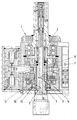
- the tapping apparatus 1 shown comprises a clamping head 2 which both rotating and axially extendable against the action of a spring 3 in the housing 4 is stored.
- the bearing is designed so that the shaft 5 of the Clamping head 2 is non-rotatably but axially displaceably connected to a sleeve 6.
- the shaft 5 has a groove 7 and the sleeve 6 has one of these grooves 7 facing groove 8, engage in the balls 9.
- the sleeve 6 is in turn in the housing with the help of the ball bearing 10 and Circlips 11 axially immovable but rotatably mounted with respect to the housing.
- This enables the advantageous use of oil seals 12 for sealing the sleeve 6 relative to the housing 4, yes Simmerrings for sealing parts rotating against each other are particularly suitable.
- the seal the shaft 5 of the clamping head 2 relative to the sleeve 6 is made with the aid of O-rings 13, for sealing axially movable parts, such as it represent the clamping head shaft 5 and the sleeve 6, are particularly cheap.
Landscapes
- Engineering & Computer Science (AREA)
- Mechanical Engineering (AREA)
- Gripping On Spindles (AREA)
- Treatment Of Fiber Materials (AREA)
- Automatic Assembly (AREA)
- Pivots And Pivotal Connections (AREA)
- Dowels (AREA)
- Paper (AREA)
- Road Signs Or Road Markings (AREA)
- Gasket Seals (AREA)
Abstract
Description
Claims (5)
- Gewindeschneidapparat mit einem rotierend und ausziehbaren in einem Gehäuse abgedichtet gelagerten Spannkopf, insbesondere für einen Gewindeschneidapparat mit Drehrichtungsumkehr, dadurch gekennzeichnet, dass der Spannkopfschaft (5) drehfest aber axial verschiebbar abgedichtet in einer Hülse (6) gelagert ist, die ihrerseits drehbar aber axial unverschiebbar abgedichtet im Gehäuse (4) gelagert ist.
- Spannkopf nach Anspruch 1, dadurch gekennzeichnet, dass der Spannkopfschaft (5) über O-Ringe (13) gegen die Hülse (6) abgedichtet ist.
- Spannkopf nach Anspruch 1 oder 2, dadurch gekennzeichnet, dass die Hülse (6) über Simmerringe (12) gegen das Gehäuse (4) abgedichtet ist.
- Spannkopf nach einem der Ansprüche 1 bis 3, dadurch gekennzeichnet, dass der Spannkopfschaft (5) und die Hülse (6) durch in einander zugewandte Längsnuten (7, 8) eingreifende Kugeln (9) drehfest und axial verschiebbar miteinander verbunden sind.
- Spannkopf nach einem der Ansprüche 1 bis 4, dadurch gekennzeichnet, dass die Hülse (6) über Kugellager (10) drehbar aber axial unverschiebbar im Gehäuse (4) gelagert ist.
Applications Claiming Priority (2)
| Application Number | Priority Date | Filing Date | Title |
|---|---|---|---|
| DE10000175A DE10000175B4 (de) | 2000-01-05 | 2000-01-05 | Gewindeschneidapparat mit abgedichtetem Spannkopf |
| DE10000175 | 2000-01-05 |
Publications (3)
| Publication Number | Publication Date |
|---|---|
| EP1132165A2 true EP1132165A2 (de) | 2001-09-12 |
| EP1132165A3 EP1132165A3 (de) | 2003-03-19 |
| EP1132165B1 EP1132165B1 (de) | 2005-04-13 |
Family
ID=7626771
Family Applications (1)
| Application Number | Title | Priority Date | Filing Date |
|---|---|---|---|
| EP00125735A Expired - Lifetime EP1132165B1 (de) | 2000-01-05 | 2000-11-24 | Gewindeschneidapparat mit abgedichtetem Spannkopf |
Country Status (4)
| Country | Link |
|---|---|
| EP (1) | EP1132165B1 (de) |
| AT (1) | ATE293026T1 (de) |
| DE (2) | DE10000175B4 (de) |
| ES (1) | ES2237376T3 (de) |
Family Cites Families (7)
| Publication number | Priority date | Publication date | Assignee | Title |
|---|---|---|---|---|
| DE1281243B (de) * | 1957-01-26 | |||
| DE1185458B (de) * | 1958-10-01 | 1965-01-14 | Licentia Gmbh | Drehrichtungsumkehrbares Getriebe mit UEberlastkupplung fuer vorzugsweise elektromotorisch angetriebene Gewindeschneider, Schrauber u. dgl. |
| NL284239A (de) * | 1961-10-11 | |||
| DE1902279A1 (de) * | 1969-01-17 | 1970-07-30 | Scharmann & Co | Vorrichtung zum Bohren von Sackloechern und zum Schneiden von Gewinden bestimmter Tiefe |
| DE2364612A1 (de) * | 1973-12-24 | 1975-06-26 | Feinbau Maschinen Gmbh | Kopf als traeger eines gewindebohrerspannfutters |
| DE3436512A1 (de) * | 1984-10-05 | 1986-04-10 | Joachim-Andreas Dipl.-Ing. Wozar (FH), 7300 Esslingen | Gewindeschneidapparat |
| DE4112467A1 (de) * | 1991-04-17 | 1992-10-22 | Bilz Otto Werkzeug | Gewindeschneidapparat |
-
2000
- 2000-01-05 DE DE10000175A patent/DE10000175B4/de not_active Expired - Fee Related
- 2000-11-24 ES ES00125735T patent/ES2237376T3/es not_active Expired - Lifetime
- 2000-11-24 EP EP00125735A patent/EP1132165B1/de not_active Expired - Lifetime
- 2000-11-24 AT AT00125735T patent/ATE293026T1/de not_active IP Right Cessation
- 2000-11-24 DE DE50010044T patent/DE50010044D1/de not_active Expired - Lifetime
Also Published As
| Publication number | Publication date |
|---|---|
| DE50010044D1 (de) | 2005-05-19 |
| DE10000175B4 (de) | 2005-06-16 |
| ES2237376T3 (es) | 2005-08-01 |
| EP1132165B1 (de) | 2005-04-13 |
| EP1132165A3 (de) | 2003-03-19 |
| ATE293026T1 (de) | 2005-04-15 |
| DE10000175A1 (de) | 2001-07-19 |
Similar Documents
| Publication | Publication Date | Title |
|---|---|---|
| EP0223738B1 (de) | Werkzeughalter für Bohr- und Meisselwerkzeuge | |
| DE2806117C2 (de) | Elektrisch betätigbarer Fensterantrieb, insbesondere für Kraftfahrzeuge | |
| DE102011119237B4 (de) | Drehschieber | |
| DE2043540A1 (de) | In sich geschlossener mechanischer Antrieb | |
| DE202004009168U1 (de) | Elektrohandwerkzeug vom Winkeltyp | |
| DE3215219A1 (de) | Zahnaerztliches handstueck | |
| EP0131771A1 (de) | Bohreinrichtung, insbesondere zur Verwendung im untertägigen Grubenbetrieb | |
| DE102008028335B3 (de) | Linearer Stellantieb für Sitz- und/oder Liegemöbel | |
| DE102014016790A1 (de) | Medizinisches Instrument | |
| DE7710413U1 (de) | Vorrichtung zur anzeige der stellung eines betaetigungsgliedes | |
| DE3320306A1 (de) | Ventilaktuator | |
| EP1132165B1 (de) | Gewindeschneidapparat mit abgedichtetem Spannkopf | |
| DE2311496A1 (de) | Zahnaerztliches handstueck | |
| DE2809221A1 (de) | Zahnstangengetriebe | |
| DE2823605A1 (de) | Wasser- und staubsichere abdichtung fuer ein drehbares bedienungselement bei einer kamera | |
| DE202004019692U1 (de) | Drehriegelschloß | |
| DE3714679A1 (de) | Werkzeughalter | |
| DE1576142C3 (de) | Hydraulisch oder pneumatisch betätig ter Drehantrieb | |
| DE2830360A1 (de) | Antriebsvorrichtung fuer rolladen, jalousien, markisen o.dgl. | |
| DE10316722B4 (de) | Umlenkhebel | |
| DE102019102441A1 (de) | Vorreiber zum Verriegeln einer Tür | |
| DE102015202075B4 (de) | Schwenkmodul einer Anhängerkupplung | |
| DE102009023261A1 (de) | Selbsthemmender Wendelschlitzantrieb | |
| DE3107648C1 (de) | Ventilanborarmatur | |
| DE8433321U1 (de) | Handhabe für Werkzeuge |
Legal Events
| Date | Code | Title | Description |
|---|---|---|---|
| PUAI | Public reference made under article 153(3) epc to a published international application that has entered the european phase |
Free format text: ORIGINAL CODE: 0009012 |
|
| AK | Designated contracting states |
Kind code of ref document: A2 Designated state(s): AT BE CH CY DE DK ES FI FR GB GR IE IT LI LU MC NL PT SE TR |
|
| AX | Request for extension of the european patent |
Free format text: AL;LT;LV;MK;RO;SI |
|
| PUAL | Search report despatched |
Free format text: ORIGINAL CODE: 0009013 |
|
| AK | Designated contracting states |
Designated state(s): AT BE CH CY DE DK ES FI FR GB GR IE IT LI LU MC NL PT SE TR Kind code of ref document: A3 Designated state(s): AT BE CH CY DE DK ES FI FR GB GR IE IT LI LU MC NL PT SE TR |
|
| AX | Request for extension of the european patent |
Extension state: AL LT LV MK RO SI |
|
| 17P | Request for examination filed |
Effective date: 20030411 |
|
| AKX | Designation fees paid |
Designated state(s): AT BE CH CY DE DK ES FI FR GB GR IE IT LI LU MC NL PT SE TR |
|
| RAP1 | Party data changed (applicant data changed or rights of an application transferred) |
Owner name: EMUGE-WERK RICHARD GLIMPEL GMBH & CO.KG FABRIK |
|
| GRAP | Despatch of communication of intention to grant a patent |
Free format text: ORIGINAL CODE: EPIDOSNIGR1 |
|
| GRAS | Grant fee paid |
Free format text: ORIGINAL CODE: EPIDOSNIGR3 |
|
| GRAA | (expected) grant |
Free format text: ORIGINAL CODE: 0009210 |
|
| AK | Designated contracting states |
Kind code of ref document: B1 Designated state(s): AT BE CH CY DE DK ES FI FR GB GR IE IT LI LU MC NL PT SE TR |
|
| PG25 | Lapsed in a contracting state [announced via postgrant information from national office to epo] |
Ref country code: IE Free format text: LAPSE BECAUSE OF FAILURE TO SUBMIT A TRANSLATION OF THE DESCRIPTION OR TO PAY THE FEE WITHIN THE PRESCRIBED TIME-LIMIT Effective date: 20050413 Ref country code: TR Free format text: LAPSE BECAUSE OF FAILURE TO SUBMIT A TRANSLATION OF THE DESCRIPTION OR TO PAY THE FEE WITHIN THE PRESCRIBED TIME-LIMIT Effective date: 20050413 Ref country code: FI Free format text: LAPSE BECAUSE OF FAILURE TO SUBMIT A TRANSLATION OF THE DESCRIPTION OR TO PAY THE FEE WITHIN THE PRESCRIBED TIME-LIMIT Effective date: 20050413 Ref country code: NL Free format text: LAPSE BECAUSE OF FAILURE TO SUBMIT A TRANSLATION OF THE DESCRIPTION OR TO PAY THE FEE WITHIN THE PRESCRIBED TIME-LIMIT Effective date: 20050413 |
|
| REG | Reference to a national code |
Ref country code: GB Ref legal event code: FG4D Free format text: NOT ENGLISH |
|
| REG | Reference to a national code |
Ref country code: CH Ref legal event code: EP |
|
| REG | Reference to a national code |
Ref country code: IE Ref legal event code: FG4D Free format text: LANGUAGE OF EP DOCUMENT: GERMAN |
|
| REF | Corresponds to: |
Ref document number: 50010044 Country of ref document: DE Date of ref document: 20050519 Kind code of ref document: P |
|
| PG25 | Lapsed in a contracting state [announced via postgrant information from national office to epo] |
Ref country code: GR Free format text: LAPSE BECAUSE OF FAILURE TO SUBMIT A TRANSLATION OF THE DESCRIPTION OR TO PAY THE FEE WITHIN THE PRESCRIBED TIME-LIMIT Effective date: 20050713 Ref country code: SE Free format text: LAPSE BECAUSE OF FAILURE TO SUBMIT A TRANSLATION OF THE DESCRIPTION OR TO PAY THE FEE WITHIN THE PRESCRIBED TIME-LIMIT Effective date: 20050713 Ref country code: DK Free format text: LAPSE BECAUSE OF FAILURE TO SUBMIT A TRANSLATION OF THE DESCRIPTION OR TO PAY THE FEE WITHIN THE PRESCRIBED TIME-LIMIT Effective date: 20050713 |
|
| REG | Reference to a national code |
Ref country code: ES Ref legal event code: FG2A Ref document number: 2237376 Country of ref document: ES Kind code of ref document: T3 |
|
| GBT | Gb: translation of ep patent filed (gb section 77(6)(a)/1977) |
Effective date: 20050718 |
|
| PG25 | Lapsed in a contracting state [announced via postgrant information from national office to epo] |
Ref country code: PT Free format text: LAPSE BECAUSE OF FAILURE TO SUBMIT A TRANSLATION OF THE DESCRIPTION OR TO PAY THE FEE WITHIN THE PRESCRIBED TIME-LIMIT Effective date: 20050913 |
|
| NLV1 | Nl: lapsed or annulled due to failure to fulfill the requirements of art. 29p and 29m of the patents act | ||
| PG25 | Lapsed in a contracting state [announced via postgrant information from national office to epo] |
Ref country code: CY Free format text: LAPSE BECAUSE OF FAILURE TO SUBMIT A TRANSLATION OF THE DESCRIPTION OR TO PAY THE FEE WITHIN THE PRESCRIBED TIME-LIMIT Effective date: 20051124 Ref country code: AT Free format text: LAPSE BECAUSE OF NON-PAYMENT OF DUE FEES Effective date: 20051124 Ref country code: IT Free format text: LAPSE BECAUSE OF NON-PAYMENT OF DUE FEES Effective date: 20051124 |
|
| PG25 | Lapsed in a contracting state [announced via postgrant information from national office to epo] |
Ref country code: CH Free format text: LAPSE BECAUSE OF NON-PAYMENT OF DUE FEES Effective date: 20051130 Ref country code: LU Free format text: LAPSE BECAUSE OF NON-PAYMENT OF DUE FEES Effective date: 20051130 Ref country code: MC Free format text: LAPSE BECAUSE OF NON-PAYMENT OF DUE FEES Effective date: 20051130 Ref country code: LI Free format text: LAPSE BECAUSE OF NON-PAYMENT OF DUE FEES Effective date: 20051130 Ref country code: BE Free format text: LAPSE BECAUSE OF NON-PAYMENT OF DUE FEES Effective date: 20051130 |
|
| REG | Reference to a national code |
Ref country code: IE Ref legal event code: FD4D |
|
| ET | Fr: translation filed | ||
| PLBE | No opposition filed within time limit |
Free format text: ORIGINAL CODE: 0009261 |
|
| STAA | Information on the status of an ep patent application or granted ep patent |
Free format text: STATUS: NO OPPOSITION FILED WITHIN TIME LIMIT |
|
| 26N | No opposition filed |
Effective date: 20060116 |
|
| REG | Reference to a national code |
Ref country code: CH Ref legal event code: PL |
|
| BERE | Be: lapsed |
Owner name: EMUGE-WERK RICHARD GLIMPEL G.M.B.H. & CO.KG FABRIK Effective date: 20051130 |
|
| PGFP | Annual fee paid to national office [announced via postgrant information from national office to epo] |
Ref country code: GB Payment date: 20090923 Year of fee payment: 10 |
|
| PGRI | Patent reinstated in contracting state [announced from national office to epo] |
Ref country code: IT Effective date: 20091001 |
|
| PGFP | Annual fee paid to national office [announced via postgrant information from national office to epo] |
Ref country code: DE Payment date: 20091125 Year of fee payment: 10 Ref country code: ES Payment date: 20091027 Year of fee payment: 10 |
|
| PGFP | Annual fee paid to national office [announced via postgrant information from national office to epo] |
Ref country code: IT Payment date: 20091124 Year of fee payment: 10 Ref country code: FR Payment date: 20091211 Year of fee payment: 10 |
|
| GBPC | Gb: european patent ceased through non-payment of renewal fee |
Effective date: 20101124 |
|
| REG | Reference to a national code |
Ref country code: FR Ref legal event code: ST Effective date: 20110801 |
|
| REG | Reference to a national code |
Ref country code: DE Ref legal event code: R119 Ref document number: 50010044 Country of ref document: DE Effective date: 20110601 Ref country code: DE Ref legal event code: R119 Ref document number: 50010044 Country of ref document: DE Effective date: 20110531 |
|
| PG25 | Lapsed in a contracting state [announced via postgrant information from national office to epo] |
Ref country code: DE Free format text: LAPSE BECAUSE OF NON-PAYMENT OF DUE FEES Effective date: 20110531 |
|
| PG25 | Lapsed in a contracting state [announced via postgrant information from national office to epo] |
Ref country code: FR Free format text: LAPSE BECAUSE OF NON-PAYMENT OF DUE FEES Effective date: 20101130 |
|
| PG25 | Lapsed in a contracting state [announced via postgrant information from national office to epo] |
Ref country code: GB Free format text: LAPSE BECAUSE OF NON-PAYMENT OF DUE FEES Effective date: 20101124 |
|
| PG25 | Lapsed in a contracting state [announced via postgrant information from national office to epo] |
Ref country code: IT Free format text: LAPSE BECAUSE OF NON-PAYMENT OF DUE FEES Effective date: 20101124 |
|
| REG | Reference to a national code |
Ref country code: ES Ref legal event code: FD2A Effective date: 20120110 |
|
| PG25 | Lapsed in a contracting state [announced via postgrant information from national office to epo] |
Ref country code: ES Free format text: LAPSE BECAUSE OF NON-PAYMENT OF DUE FEES Effective date: 20101125 |