EP1132248A2 - Aufhängevorrichtung für einen Tank - Google Patents
Aufhängevorrichtung für einen Tank Download PDFInfo
- Publication number
- EP1132248A2 EP1132248A2 EP01104841A EP01104841A EP1132248A2 EP 1132248 A2 EP1132248 A2 EP 1132248A2 EP 01104841 A EP01104841 A EP 01104841A EP 01104841 A EP01104841 A EP 01104841A EP 1132248 A2 EP1132248 A2 EP 1132248A2
- Authority
- EP
- European Patent Office
- Prior art keywords
- container
- vertical
- hooking means
- support member
- section
- Prior art date
- Legal status (The legal status is an assumption and is not a legal conclusion. Google has not performed a legal analysis and makes no representation as to the accuracy of the status listed.)
- Granted
Links
- 239000000725 suspension Substances 0.000 title claims abstract description 9
- 239000002828 fuel tank Substances 0.000 claims abstract description 4
- 230000000295 complement effect Effects 0.000 claims description 2
- 230000000284 resting effect Effects 0.000 abstract description 2
- 230000003014 reinforcing effect Effects 0.000 description 2
- 238000010276 construction Methods 0.000 description 1
- 239000002184 metal Substances 0.000 description 1
- XLYOFNOQVPJJNP-UHFFFAOYSA-N water Substances O XLYOFNOQVPJJNP-UHFFFAOYSA-N 0.000 description 1
- 238000003466 welding Methods 0.000 description 1
Images


Classifications
-
- B—PERFORMING OPERATIONS; TRANSPORTING
- B60—VEHICLES IN GENERAL
- B60K—ARRANGEMENT OR MOUNTING OF PROPULSION UNITS OR OF TRANSMISSIONS IN VEHICLES; ARRANGEMENT OR MOUNTING OF PLURAL DIVERSE PRIME-MOVERS IN VEHICLES; AUXILIARY DRIVES FOR VEHICLES; INSTRUMENTATION OR DASHBOARDS FOR VEHICLES; ARRANGEMENTS IN CONNECTION WITH COOLING, AIR INTAKE, GAS EXHAUST OR FUEL SUPPLY OF PROPULSION UNITS IN VEHICLES
- B60K15/00—Arrangement in connection with fuel supply of combustion engines or other fuel consuming energy converters, e.g. fuel cells; Mounting or construction of fuel tanks
- B60K15/03—Fuel tanks
- B60K15/063—Arrangement of tanks
- B60K15/067—Mounting of tanks
Definitions
- the present invention concerns a suspension arrangement for a container on a side member in a vehicle, preferably a lorry, the arrangement comprising a largely vertical support member mounted on the side member and including means for supporting the container.
- containers in the form of fuel tanks, tool boxes, oil tanks, water tanks and the like have been disposed by unilateral suspension on the side member of a lorry under the platform body of the lorry.
- the supporting means are formed by using an L-shaped bracket which is screw bolted on the side member via the vertical leg of the L thus constituting a vertical support member.
- the container is disposed upon the horizontal leg of the L.
- this L-shaped bracket has a relatively great height of between 5 and 10 cm. This causes a part of the space available under the platform of the lorry to be occupied by the horizontal leg of the L-shaped bracket resulting in less useful volume in the tank. This is a drawback.
- a vertical support member in the shape of a U-section is screwed onto the side member.
- a flat bar which is welded onto the tank, is screwed on the U-shaped section at the top, and a plate is welded into the U-section at the bottom for supporting the tank at bottom.
- the supporting means comprise a hooking means engaging a complementary hooking means which is mounted at a vertical side of the container as the two mutually engaging hooking means comprise an upwardly facing groove and a downwardly facing profiled edge arranged to engage the groove, and that at the vertical side of the container there is provided a projecting edge extending largely in parallel with the hooking means, and which may pivot into engagement behind a downwardly facing surface connected with the support member by pivoting the container about the mutually engaging hooking means.
- the arrangement is peculiar in that the hooking means comprise a quadrangular section fastened at an upper end of the vertical support member and engaging a U-section on the container with the open part of the U facing downward, the support member comprising one or more juxtaposed vertical U-sections that have a downwardly facing surface at each their lower end, the surface formed in a recess arranged to receive an angle bar which is fastened at the bottom of the container.
- the arrangement may be further peculiar in that the vertical U-sections are fastened with screw bolts on a C-shaped side member, and that one leg of the angle bar is welded onto the bottom of the container, and that the other leg, which protrudes outside the vertical side, is brought into contact with the bottom of the recess and is fastened with screw bolts to the vertical U-sections.
- This embodiment is particularly simple to make and to mount in connection with metal containers such a fuel tanks.
- the arrangement is peculiar in that the hooking means comprise quadrangular section fastened at a lower end of the vertical support member and engaging a U-section on the container with the open part of the U facing downward, the support member comprising one or more juxtaposed, vertical C-sections that each have a hole formed in the upper part of the side member and in line with a hole in a plate fastened at the top of the container, and that a screw bolt through the holes fastens the container.
- the hooking means comprise quadrangular section fastened at a lower end of the vertical support member and engaging a U-section on the container with the open part of the U facing downward
- the support member comprising one or more juxtaposed, vertical C-sections that each have a hole formed in the upper part of the side member and in line with a hole in a plate fastened at the top of the container, and that a screw bolt through the holes fastens the container.
- the arrangement may be peculiar in that the hooking means comprise a V-shaped groove provided at an upper end of the vertical support member and engaging a V-shaped section with a downward facing edge, the support member comprising one or more juxtaposed vertical U-sections each having a surface at their downward facing ends formed in a recess which is arranged for receiving an angle bar fastened at the bottom of the container.
- This embodiment causes that the hooking means automatically slide into engagement and simultaneously enable a wedge action as the triangular section slides down into the groove.
- hooking means are possible. It is only important to ensure that the hooking means are disposed on the side member and the container so that the upper side of the container and the side member are largely in the same horizontal plane when the hooking means are engaged. Also, it is advantageous if the hooking means are elongate and have a length corresponding to the length of the mentioned vertical side of the container. Hereby a great load may be carried by the hooking means.
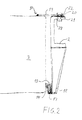
- the arrangement shown in Fig. 1 comprises a vertical U-section 1 screwed onto a lorry side member 2 as in the case of the prior art arrangements.
- a tank 3 At the bottom 4 and in longitudinal direction of the container, which is shown as a tank 3, an angle bar 5 is welded on.
- This angle bar engages a recess in the U-section 1.
- the angle bar may be screwed into the U-section by means of bolts 9 for further safeguarding against the tank falling off during driving.
- a reinforcing plate 11 which at its outer end 12 is provided with a U-section 13 extending along the tank. This U-section grips as a hook down on a support section 14 fastened at the upper side of the U-section 1.
- Fig. 2 is shown an alternative embodiment of the arrangement.
- This embodiment differs from the embodiment in Fig. 1 by the horizontal U-section 13 and the support section 14 being disposed at the bottom 4 of the tank 3 as the support section 14 via an angular bracket 17 is mounted at the lower end of a U-section 18 which is shown with a downwardly directed tapering and is appearing at the underside of the side member 2.
- the mounting may occur by screw bolting, welding, or in other ways.
- a connecting plate 19 extending beyond the side member 2.
- the connecting plate is provided with a hole 20 which is brought to a position at a hole 21 in the side member 2 after which a bolt 22 is used for fastening the tank.
- the tank is thus placed by hooking the U-section 13 over the support section 14 and then pivot the upper part of the tank inwards so that the plate 19 is over the side member 2. Then the tank is aligned longitudinally until the holes 20 and 21 are corresponding with each other.
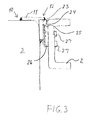
- Fig. 3 is shown a partial illustration of a further embodiment. Only the upper part of the tank is shown as the lower part of the tank will correspond to the embodiment shown in Fig. 1.
- This embodiment differs by reinforcing plate 11 being provided with a section 23 with a profiled V-shaped edge 24 at its outer end. This V-shaped edge engages a corresponding V-shaped groove 25 provided at the upper side of a section 26 which is fastened to the side member 2 by means of bolts 27. Thereby the V-shaped part 24 is easily hooked and brought into engagement with the V-shaped groove 25 and will automatically be leading into abutment against the side member 2.
- An angle bar 5 (see Fig. 1) ensures that the tank does not fall off during driving.
- Fig. 4 is shown a further embodiment. Here is shown hooking elements corresponding to those shown in Fig. 3. However, here they are provided at the bottom 4 of the tank 3. At the upper end of the tank there is provided a plate corresponding to the plate 19 in Fig. 2 for similar fastening of the tank on the side member 2.
- the safeguarding of the tank against falling off during driving is provided by means of the bolt 20.
- the underside 28 of the bolt head will form a surface for engaging the connecting plate 19.
- holes 20 in the plate 19 and the side member 2 there may be used an elongate opening in the side of the plate 19 and/or the side member 2.
- a corresponding safety device (not shown) is used in the embodiment shown in Fig. 4.
Landscapes
- Engineering & Computer Science (AREA)
- Transportation (AREA)
- Sustainable Development (AREA)
- Sustainable Energy (AREA)
- Chemical & Material Sciences (AREA)
- Combustion & Propulsion (AREA)
- Life Sciences & Earth Sciences (AREA)
- Mechanical Engineering (AREA)
- Details Of Rigid Or Semi-Rigid Containers (AREA)
- Cooling, Air Intake And Gas Exhaust, And Fuel Tank Arrangements In Propulsion Units (AREA)
- Electrical Discharge Machining, Electrochemical Machining, And Combined Machining (AREA)
- Centrifugal Separators (AREA)
- Control And Other Processes For Unpacking Of Materials (AREA)
Priority Applications (1)
| Application Number | Priority Date | Filing Date | Title |
|---|---|---|---|
| DK01104841T DK1132248T3 (da) | 2000-03-07 | 2001-02-28 | Ophængningsarrangement |
Applications Claiming Priority (2)
| Application Number | Priority Date | Filing Date | Title |
|---|---|---|---|
| DK200000365A DK173860B1 (da) | 2000-03-07 | 2000-03-07 | Ophængningsarrangement for beholder |
| DK200000365 | 2000-03-07 |
Publications (3)
| Publication Number | Publication Date |
|---|---|
| EP1132248A2 true EP1132248A2 (de) | 2001-09-12 |
| EP1132248A3 EP1132248A3 (de) | 2003-05-02 |
| EP1132248B1 EP1132248B1 (de) | 2006-02-01 |
Family
ID=8159289
Family Applications (1)
| Application Number | Title | Priority Date | Filing Date |
|---|---|---|---|
| EP01104841A Expired - Lifetime EP1132248B1 (de) | 2000-03-07 | 2001-02-28 | Aufhängevorrichtung für einen Tank |
Country Status (4)
| Country | Link |
|---|---|
| EP (1) | EP1132248B1 (de) |
| AT (1) | ATE316875T1 (de) |
| DE (1) | DE60116910T2 (de) |
| DK (2) | DK173860B1 (de) |
Cited By (5)
| Publication number | Priority date | Publication date | Assignee | Title |
|---|---|---|---|---|
| AT505396B1 (de) * | 2007-11-29 | 2009-01-15 | Alutech Gmbh | Fahrzeugtank und befestigungssystem hiefür |
| DE102012000402B3 (de) * | 2012-01-12 | 2013-04-11 | Salzburger Aluminium Ag | Konsole zur Halterung eines Tanks |
| JP2013527818A (ja) * | 2010-04-08 | 2013-07-04 | スカニア シーブイ アクチボラグ | 車両のための取付け装置 |
| CN110139769A (zh) * | 2017-01-18 | 2019-08-16 | 斯堪尼亚商用车有限公司 | 一种悬挂装置 |
| DK181452B1 (en) * | 2022-03-04 | 2024-01-26 | Dantank As | Suspension device for suspending a container to a vehicle |
Families Citing this family (4)
| Publication number | Priority date | Publication date | Assignee | Title |
|---|---|---|---|---|
| DE102006051389A1 (de) * | 2006-10-27 | 2008-04-30 | Elkamet Kunststofftechnik Gmbh | Verfahren und Vorrichtung zur Behältermontage |
| DE102006051390A1 (de) * | 2006-10-27 | 2008-04-30 | Elkamet Kunststofftechnik Gmbh | Kunststoffbehälter |
| DE102008027291A1 (de) | 2008-06-06 | 2009-12-10 | J. Eberspächer GmbH & Co. KG | Halteeinrichtung für ein Fahrzeuganbauteil |
| DE102016010010A1 (de) * | 2016-08-17 | 2018-02-22 | Liebherr-Mining Equipment Colmar Sas | Vorrichtung zur kraft- und/oder formschlüssigen Befestigung eines Tanks an einem Fahrzeugrahmen |
Family Cites Families (4)
| Publication number | Priority date | Publication date | Assignee | Title |
|---|---|---|---|---|
| US1797873A (en) * | 1929-06-06 | 1931-03-24 | Int Motor Co | Combined gas tank and running-board apron |
| IT8368348A0 (it) * | 1983-12-23 | 1983-12-23 | Torino A | Serbatoio combustibile con mensole incorporate per autoveicoli |
| JPH0340879Y2 (de) * | 1986-07-25 | 1991-08-28 | ||
| DE9406777U1 (de) * | 1994-04-22 | 1994-07-07 | Severit, Ernst, 49565 Bramsche | Tankbefestigung |
-
2000
- 2000-03-07 DK DK200000365A patent/DK173860B1/da not_active IP Right Cessation
-
2001
- 2001-02-28 DE DE60116910T patent/DE60116910T2/de not_active Expired - Lifetime
- 2001-02-28 EP EP01104841A patent/EP1132248B1/de not_active Expired - Lifetime
- 2001-02-28 DK DK01104841T patent/DK1132248T3/da active
- 2001-02-28 AT AT01104841T patent/ATE316875T1/de not_active IP Right Cessation
Non-Patent Citations (1)
| Title |
|---|
| None |
Cited By (8)
| Publication number | Priority date | Publication date | Assignee | Title |
|---|---|---|---|---|
| AT505396B1 (de) * | 2007-11-29 | 2009-01-15 | Alutech Gmbh | Fahrzeugtank und befestigungssystem hiefür |
| EP2065247A1 (de) | 2007-11-29 | 2009-06-03 | Alutech Gesellschaft m.b.H. | Fahrzeugtank und Befestigungssystem hiefür |
| JP2013527818A (ja) * | 2010-04-08 | 2013-07-04 | スカニア シーブイ アクチボラグ | 車両のための取付け装置 |
| US8960617B2 (en) | 2010-04-08 | 2015-02-24 | Scania Cv Ab | Suspension device for vehicle |
| DE102012000402B3 (de) * | 2012-01-12 | 2013-04-11 | Salzburger Aluminium Ag | Konsole zur Halterung eines Tanks |
| CN110139769A (zh) * | 2017-01-18 | 2019-08-16 | 斯堪尼亚商用车有限公司 | 一种悬挂装置 |
| DK181452B1 (en) * | 2022-03-04 | 2024-01-26 | Dantank As | Suspension device for suspending a container to a vehicle |
| DK202270088A1 (en) * | 2022-03-04 | 2024-01-26 | Dantank As | Suspension arrangement for suspend a container to a vehi-cle |
Also Published As
| Publication number | Publication date |
|---|---|
| ATE316875T1 (de) | 2006-02-15 |
| DK1132248T3 (da) | 2006-05-29 |
| EP1132248B1 (de) | 2006-02-01 |
| DK173860B1 (da) | 2002-01-07 |
| DE60116910T2 (de) | 2006-09-21 |
| DK200000365A (da) | 2001-09-08 |
| EP1132248A3 (de) | 2003-05-02 |
| DE60116910D1 (de) | 2006-04-13 |
Similar Documents
| Publication | Publication Date | Title |
|---|---|---|
| US4316688A (en) | Reinforcing removable post pocket tie-down | |
| US20210114669A1 (en) | Modular truck bed rack system and portions thereof | |
| US7731462B2 (en) | Bulkhead for dividing a cargo container into two compartments | |
| US4812093A (en) | Stake pocket tie-down anchor | |
| EP1132248B1 (de) | Aufhängevorrichtung für einen Tank | |
| US5118156A (en) | Auxiliary load carrier for cargo box | |
| US4867497A (en) | Load supporting rack for attachment to pick-up truck box | |
| US5470120A (en) | Base rail for utility rack | |
| US7419075B2 (en) | Utility rack for pickup trucks | |
| US20020057001A1 (en) | Moveable truck toolbox and truck toolbox moving system | |
| US6193452B1 (en) | Hold-down device for pick-up truck cargo beds | |
| CN206466040U (zh) | 卡车货箱固定结构 | |
| US5251947A (en) | Chain box | |
| US5454612A (en) | Pick-up truck rail with anchor slots | |
| US6176658B1 (en) | Support bar with tie-down posts, for pick-up trucks and the like | |
| US12345079B2 (en) | Stake post with locking hinge | |
| US8430286B1 (en) | Boat carrying rack for use on transporting vehicles | |
| US4629085A (en) | Frame structure for accommodating a plurality of containers | |
| US20050249551A1 (en) | Barrier element | |
| US6168359B1 (en) | Apparatus and method for securing a load in the flat bed area of a vehicle | |
| US20100264669A1 (en) | Generator frame with grappling attachment feature and theft deterring weight receptacle | |
| KR200468752Y1 (ko) | 제설제 보관함 설치를 위한 가드레일용 거치대 | |
| US5957351A (en) | Clamped-on storage rack means for flat bed trailers | |
| US6254047B1 (en) | Equipment roller/slide support | |
| EP0274788A1 (de) | Tragkonstruktion für gezogene Fahrzeuge |
Legal Events
| Date | Code | Title | Description |
|---|---|---|---|
| PUAI | Public reference made under article 153(3) epc to a published international application that has entered the european phase |
Free format text: ORIGINAL CODE: 0009012 |
|
| AK | Designated contracting states |
Kind code of ref document: A2 Designated state(s): AT BE CH CY DE DK ES FI FR GB GR IE IT LI LU MC NL PT SE TR |
|
| AX | Request for extension of the european patent |
Free format text: AL;LT;LV;MK;RO;SI |
|
| RAP1 | Party data changed (applicant data changed or rights of an application transferred) |
Owner name: SORENSEN, POUL OLE Owner name: ROGE, TORBEN JACOB |
|
| PUAL | Search report despatched |
Free format text: ORIGINAL CODE: 0009013 |
|
| AK | Designated contracting states |
Designated state(s): AT BE CH CY DE DK ES FI FR GB GR IE IT LI LU MC NL PT SE TR |
|
| AX | Request for extension of the european patent |
Extension state: AL LT LV MK RO SI |
|
| RIC1 | Information provided on ipc code assigned before grant |
Ipc: 7B 62D 21/16 B Ipc: 7B 60R 9/055 B Ipc: 7B 65D 85/68 B Ipc: 7B 60K 15/067 A Ipc: 7B 60R 11/00 B |
|
| 17P | Request for examination filed |
Effective date: 20031024 |
|
| AKX | Designation fees paid |
Designated state(s): AT BE CH CY DE DK ES FI FR GB GR IE IT LI LU MC NL PT SE TR |
|
| GRAP | Despatch of communication of intention to grant a patent |
Free format text: ORIGINAL CODE: EPIDOSNIGR1 |
|
| GRAS | Grant fee paid |
Free format text: ORIGINAL CODE: EPIDOSNIGR3 |
|
| GRAA | (expected) grant |
Free format text: ORIGINAL CODE: 0009210 |
|
| RIN1 | Information on inventor provided before grant (corrected) |
Inventor name: SORENSEN, POUL OLE Inventor name: ROGE, TORBEN JACOB |
|
| RIN1 | Information on inventor provided before grant (corrected) |
Inventor name: ROGE, TORBEN JACOB Inventor name: SORENSEN, POUL OLE |
|
| AK | Designated contracting states |
Kind code of ref document: B1 Designated state(s): AT BE CH CY DE DK ES FI FR GB GR IE IT LI LU MC NL PT SE TR |
|
| PG25 | Lapsed in a contracting state [announced via postgrant information from national office to epo] |
Ref country code: IT Free format text: LAPSE BECAUSE OF FAILURE TO SUBMIT A TRANSLATION OF THE DESCRIPTION OR TO PAY THE FEE WITHIN THE PRESCRIBED TIME-LIMIT;WARNING: LAPSES OF ITALIAN PATENTS WITH EFFECTIVE DATE BEFORE 2007 MAY HAVE OCCURRED AT ANY TIME BEFORE 2007. THE CORRECT EFFECTIVE DATE MAY BE DIFFERENT FROM THE ONE RECORDED. Effective date: 20060201 Ref country code: CH Free format text: LAPSE BECAUSE OF FAILURE TO SUBMIT A TRANSLATION OF THE DESCRIPTION OR TO PAY THE FEE WITHIN THE PRESCRIBED TIME-LIMIT Effective date: 20060201 Ref country code: FI Free format text: LAPSE BECAUSE OF FAILURE TO SUBMIT A TRANSLATION OF THE DESCRIPTION OR TO PAY THE FEE WITHIN THE PRESCRIBED TIME-LIMIT Effective date: 20060201 Ref country code: AT Free format text: LAPSE BECAUSE OF FAILURE TO SUBMIT A TRANSLATION OF THE DESCRIPTION OR TO PAY THE FEE WITHIN THE PRESCRIBED TIME-LIMIT Effective date: 20060201 Ref country code: LI Free format text: LAPSE BECAUSE OF FAILURE TO SUBMIT A TRANSLATION OF THE DESCRIPTION OR TO PAY THE FEE WITHIN THE PRESCRIBED TIME-LIMIT Effective date: 20060201 Ref country code: BE Free format text: LAPSE BECAUSE OF FAILURE TO SUBMIT A TRANSLATION OF THE DESCRIPTION OR TO PAY THE FEE WITHIN THE PRESCRIBED TIME-LIMIT Effective date: 20060201 |
|
| REG | Reference to a national code |
Ref country code: GB Ref legal event code: FG4D |
|
| REG | Reference to a national code |
Ref country code: CH Ref legal event code: EP |
|
| PG25 | Lapsed in a contracting state [announced via postgrant information from national office to epo] |
Ref country code: MC Free format text: LAPSE BECAUSE OF NON-PAYMENT OF DUE FEES Effective date: 20060228 Ref country code: IE Free format text: LAPSE BECAUSE OF NON-PAYMENT OF DUE FEES Effective date: 20060228 |
|
| REG | Reference to a national code |
Ref country code: IE Ref legal event code: FG4D |
|
| REF | Corresponds to: |
Ref document number: 60116910 Country of ref document: DE Date of ref document: 20060413 Kind code of ref document: P |
|
| PG25 | Lapsed in a contracting state [announced via postgrant information from national office to epo] |
Ref country code: GB Free format text: LAPSE BECAUSE OF NON-PAYMENT OF DUE FEES Effective date: 20060501 |
|
| PG25 | Lapsed in a contracting state [announced via postgrant information from national office to epo] |
Ref country code: ES Free format text: LAPSE BECAUSE OF FAILURE TO SUBMIT A TRANSLATION OF THE DESCRIPTION OR TO PAY THE FEE WITHIN THE PRESCRIBED TIME-LIMIT Effective date: 20060512 |
|
| REG | Reference to a national code |
Ref country code: SE Ref legal event code: TRGR |
|
| PG25 | Lapsed in a contracting state [announced via postgrant information from national office to epo] |
Ref country code: PT Free format text: LAPSE BECAUSE OF FAILURE TO SUBMIT A TRANSLATION OF THE DESCRIPTION OR TO PAY THE FEE WITHIN THE PRESCRIBED TIME-LIMIT Effective date: 20060703 |
|
| REG | Reference to a national code |
Ref country code: CH Ref legal event code: PL |
|
| PLBE | No opposition filed within time limit |
Free format text: ORIGINAL CODE: 0009261 |
|
| STAA | Information on the status of an ep patent application or granted ep patent |
Free format text: STATUS: NO OPPOSITION FILED WITHIN TIME LIMIT |
|
| 26N | No opposition filed |
Effective date: 20061103 |
|
| GBPC | Gb: european patent ceased through non-payment of renewal fee |
Effective date: 20060501 |
|
| EN | Fr: translation not filed | ||
| PG25 | Lapsed in a contracting state [announced via postgrant information from national office to epo] |
Ref country code: GR Free format text: LAPSE BECAUSE OF FAILURE TO SUBMIT A TRANSLATION OF THE DESCRIPTION OR TO PAY THE FEE WITHIN THE PRESCRIBED TIME-LIMIT Effective date: 20060502 Ref country code: FR Free format text: LAPSE BECAUSE OF FAILURE TO SUBMIT A TRANSLATION OF THE DESCRIPTION OR TO PAY THE FEE WITHIN THE PRESCRIBED TIME-LIMIT Effective date: 20070323 |
|
| PG25 | Lapsed in a contracting state [announced via postgrant information from national office to epo] |
Ref country code: TR Free format text: LAPSE BECAUSE OF FAILURE TO SUBMIT A TRANSLATION OF THE DESCRIPTION OR TO PAY THE FEE WITHIN THE PRESCRIBED TIME-LIMIT Effective date: 20060201 Ref country code: LU Free format text: LAPSE BECAUSE OF NON-PAYMENT OF DUE FEES Effective date: 20060228 |
|
| PG25 | Lapsed in a contracting state [announced via postgrant information from national office to epo] |
Ref country code: FR Free format text: LAPSE BECAUSE OF FAILURE TO SUBMIT A TRANSLATION OF THE DESCRIPTION OR TO PAY THE FEE WITHIN THE PRESCRIBED TIME-LIMIT Effective date: 20060228 |
|
| PG25 | Lapsed in a contracting state [announced via postgrant information from national office to epo] |
Ref country code: CY Free format text: LAPSE BECAUSE OF FAILURE TO SUBMIT A TRANSLATION OF THE DESCRIPTION OR TO PAY THE FEE WITHIN THE PRESCRIBED TIME-LIMIT Effective date: 20060201 Ref country code: FR Free format text: LAPSE BECAUSE OF FAILURE TO SUBMIT A TRANSLATION OF THE DESCRIPTION OR TO PAY THE FEE WITHIN THE PRESCRIBED TIME-LIMIT Effective date: 20060201 |
|
| PGFP | Annual fee paid to national office [announced via postgrant information from national office to epo] |
Ref country code: SE Payment date: 20200227 Year of fee payment: 20 Ref country code: DE Payment date: 20200227 Year of fee payment: 20 Ref country code: NL Payment date: 20200226 Year of fee payment: 20 Ref country code: DK Payment date: 20200227 Year of fee payment: 20 |
|
| REG | Reference to a national code |
Ref country code: DE Ref legal event code: R071 Ref document number: 60116910 Country of ref document: DE |
|
| REG | Reference to a national code |
Ref country code: DK Ref legal event code: EUP Expiry date: 20210228 |
|
| REG | Reference to a national code |
Ref country code: NL Ref legal event code: MK Effective date: 20210227 |
|
| REG | Reference to a national code |
Ref country code: SE Ref legal event code: EUG |