EP1132337A1 - Méthode et dispositif pour mélanger des liquides - Google Patents
Méthode et dispositif pour mélanger des liquides Download PDFInfo
- Publication number
- EP1132337A1 EP1132337A1 EP01810088A EP01810088A EP1132337A1 EP 1132337 A1 EP1132337 A1 EP 1132337A1 EP 01810088 A EP01810088 A EP 01810088A EP 01810088 A EP01810088 A EP 01810088A EP 1132337 A1 EP1132337 A1 EP 1132337A1
- Authority
- EP
- European Patent Office
- Prior art keywords
- liquid
- main liquid
- arrangement according
- main
- secondary liquid
- Prior art date
- Legal status (The legal status is an assumption and is not a legal conclusion. Google has not performed a legal analysis and makes no representation as to the accuracy of the status listed.)
- Withdrawn
Links
- 238000000034 method Methods 0.000 title claims abstract description 43
- 238000002156 mixing Methods 0.000 title claims abstract description 41
- 239000012530 fluid Substances 0.000 title claims abstract description 27
- 239000007788 liquid Substances 0.000 claims abstract description 206
- 239000007795 chemical reaction product Substances 0.000 claims abstract description 10
- 238000006073 displacement reaction Methods 0.000 claims abstract description 10
- XLYOFNOQVPJJNP-UHFFFAOYSA-N water Substances O XLYOFNOQVPJJNP-UHFFFAOYSA-N 0.000 claims description 23
- 239000000872 buffer Substances 0.000 claims description 22
- 238000003860 storage Methods 0.000 claims description 20
- 235000013361 beverage Nutrition 0.000 claims description 19
- 238000004519 manufacturing process Methods 0.000 claims description 8
- 239000000126 substance Substances 0.000 claims description 4
- 239000007787 solid Substances 0.000 claims description 2
- 235000020965 cold beverage Nutrition 0.000 claims 2
- 239000002537 cosmetic Substances 0.000 claims 2
- 238000002360 preparation method Methods 0.000 claims 2
- BVKZGUZCCUSVTD-UHFFFAOYSA-N carbonic acid Chemical compound OC(O)=O BVKZGUZCCUSVTD-UHFFFAOYSA-N 0.000 claims 1
- 239000003795 chemical substances by application Substances 0.000 claims 1
- 230000035515 penetration Effects 0.000 claims 1
- -1 pharmaceutical Substances 0.000 claims 1
- 239000000203 mixture Substances 0.000 description 8
- CURLTUGMZLYLDI-UHFFFAOYSA-N Carbon dioxide Chemical compound O=C=O CURLTUGMZLYLDI-UHFFFAOYSA-N 0.000 description 5
- 238000001514 detection method Methods 0.000 description 5
- 239000007789 gas Substances 0.000 description 5
- 239000011159 matrix material Substances 0.000 description 5
- 239000000654 additive Substances 0.000 description 4
- 230000001419 dependent effect Effects 0.000 description 3
- 239000000835 fiber Substances 0.000 description 3
- 239000012467 final product Substances 0.000 description 3
- 239000013505 freshwater Substances 0.000 description 3
- 235000019640 taste Nutrition 0.000 description 3
- 229910002092 carbon dioxide Inorganic materials 0.000 description 2
- 239000001569 carbon dioxide Substances 0.000 description 2
- 235000008504 concentrate Nutrition 0.000 description 2
- 239000012141 concentrate Substances 0.000 description 2
- 238000001816 cooling Methods 0.000 description 2
- 238000005429 filling process Methods 0.000 description 2
- 230000003287 optical effect Effects 0.000 description 2
- 239000000843 powder Substances 0.000 description 2
- 235000020374 simple syrup Nutrition 0.000 description 2
- 235000020357 syrup Nutrition 0.000 description 2
- 239000006188 syrup Substances 0.000 description 2
- 238000009423 ventilation Methods 0.000 description 2
- 229940088594 vitamin Drugs 0.000 description 2
- 229930003231 vitamin Natural products 0.000 description 2
- 235000013343 vitamin Nutrition 0.000 description 2
- 239000011782 vitamin Substances 0.000 description 2
- IJGRMHOSHXDMSA-UHFFFAOYSA-N Atomic nitrogen Chemical compound N#N IJGRMHOSHXDMSA-UHFFFAOYSA-N 0.000 description 1
- 230000003213 activating effect Effects 0.000 description 1
- 230000033228 biological regulation Effects 0.000 description 1
- 235000014171 carbonated beverage Nutrition 0.000 description 1
- 238000004040 coloring Methods 0.000 description 1
- 238000010276 construction Methods 0.000 description 1
- 238000011109 contamination Methods 0.000 description 1
- 230000001276 controlling effect Effects 0.000 description 1
- 230000007547 defect Effects 0.000 description 1
- 235000003599 food sweetener Nutrition 0.000 description 1
- 230000006870 function Effects 0.000 description 1
- 230000005484 gravity Effects 0.000 description 1
- 239000008240 homogeneous mixture Substances 0.000 description 1
- 239000004615 ingredient Substances 0.000 description 1
- 238000012432 intermediate storage Methods 0.000 description 1
- 239000012528 membrane Substances 0.000 description 1
- 239000002245 particle Substances 0.000 description 1
- 230000036316 preload Effects 0.000 description 1
- 238000005086 pumping Methods 0.000 description 1
- 230000001105 regulatory effect Effects 0.000 description 1
- 239000003765 sweetening agent Substances 0.000 description 1
Images

Classifications
-
- B—PERFORMING OPERATIONS; TRANSPORTING
- B67—OPENING, CLOSING OR CLEANING BOTTLES, JARS OR SIMILAR CONTAINERS; LIQUID HANDLING
- B67D—DISPENSING, DELIVERING OR TRANSFERRING LIQUIDS, NOT OTHERWISE PROVIDED FOR
- B67D7/00—Apparatus or devices for transferring liquids from bulk storage containers or reservoirs into vehicles or into portable containers, e.g. for retail sale purposes
- B67D7/06—Details or accessories
- B67D7/74—Devices for mixing two or more different liquids to be transferred
-
- B—PERFORMING OPERATIONS; TRANSPORTING
- B01—PHYSICAL OR CHEMICAL PROCESSES OR APPARATUS IN GENERAL
- B01F—MIXING, e.g. DISSOLVING, EMULSIFYING OR DISPERSING
- B01F23/00—Mixing according to the phases to be mixed, e.g. dispersing or emulsifying
- B01F23/40—Mixing liquids with liquids; Emulsifying
- B01F23/49—Mixing systems, i.e. flow charts or diagrams
-
- B—PERFORMING OPERATIONS; TRANSPORTING
- B01—PHYSICAL OR CHEMICAL PROCESSES OR APPARATUS IN GENERAL
- B01F—MIXING, e.g. DISSOLVING, EMULSIFYING OR DISPERSING
- B01F35/00—Accessories for mixers; Auxiliary operations or auxiliary devices; Parts or details of general application
- B01F35/71—Feed mechanisms
- B01F35/712—Feed mechanisms for feeding fluids
-
- B—PERFORMING OPERATIONS; TRANSPORTING
- B01—PHYSICAL OR CHEMICAL PROCESSES OR APPARATUS IN GENERAL
- B01F—MIXING, e.g. DISSOLVING, EMULSIFYING OR DISPERSING
- B01F35/00—Accessories for mixers; Auxiliary operations or auxiliary devices; Parts or details of general application
- B01F35/71—Feed mechanisms
- B01F35/714—Feed mechanisms for feeding predetermined amounts
-
- B—PERFORMING OPERATIONS; TRANSPORTING
- B01—PHYSICAL OR CHEMICAL PROCESSES OR APPARATUS IN GENERAL
- B01F—MIXING, e.g. DISSOLVING, EMULSIFYING OR DISPERSING
- B01F35/00—Accessories for mixers; Auxiliary operations or auxiliary devices; Parts or details of general application
- B01F35/71—Feed mechanisms
- B01F35/717—Feed mechanisms characterised by the means for feeding the components to the mixer
- B01F35/7174—Feed mechanisms characterised by the means for feeding the components to the mixer using pistons, plungers or syringes
-
- B—PERFORMING OPERATIONS; TRANSPORTING
- B01—PHYSICAL OR CHEMICAL PROCESSES OR APPARATUS IN GENERAL
- B01F—MIXING, e.g. DISSOLVING, EMULSIFYING OR DISPERSING
- B01F35/00—Accessories for mixers; Auxiliary operations or auxiliary devices; Parts or details of general application
- B01F35/71—Feed mechanisms
- B01F35/717—Feed mechanisms characterised by the means for feeding the components to the mixer
- B01F35/7176—Feed mechanisms characterised by the means for feeding the components to the mixer using pumps
-
- B—PERFORMING OPERATIONS; TRANSPORTING
- B01—PHYSICAL OR CHEMICAL PROCESSES OR APPARATUS IN GENERAL
- B01F—MIXING, e.g. DISSOLVING, EMULSIFYING OR DISPERSING
- B01F35/00—Accessories for mixers; Auxiliary operations or auxiliary devices; Parts or details of general application
- B01F35/71—Feed mechanisms
- B01F35/717—Feed mechanisms characterised by the means for feeding the components to the mixer
- B01F35/71805—Feed mechanisms characterised by the means for feeding the components to the mixer using valves, gates, orifices or openings
-
- B—PERFORMING OPERATIONS; TRANSPORTING
- B01—PHYSICAL OR CHEMICAL PROCESSES OR APPARATUS IN GENERAL
- B01F—MIXING, e.g. DISSOLVING, EMULSIFYING OR DISPERSING
- B01F35/00—Accessories for mixers; Auxiliary operations or auxiliary devices; Parts or details of general application
- B01F35/80—Forming a predetermined ratio of the substances to be mixed
- B01F35/88—Forming a predetermined ratio of the substances to be mixed by feeding the materials batchwise
- B01F35/882—Forming a predetermined ratio of the substances to be mixed by feeding the materials batchwise using measuring chambers, e.g. volumetric pumps, for feeding the substances
-
- B—PERFORMING OPERATIONS; TRANSPORTING
- B67—OPENING, CLOSING OR CLEANING BOTTLES, JARS OR SIMILAR CONTAINERS; LIQUID HANDLING
- B67D—DISPENSING, DELIVERING OR TRANSFERRING LIQUIDS, NOT OTHERWISE PROVIDED FOR
- B67D1/00—Apparatus or devices for dispensing beverages on draught
- B67D1/0015—Apparatus or devices for dispensing beverages on draught the beverage being prepared by mixing at least two liquid components
- B67D1/0016—Apparatus or devices for dispensing beverages on draught the beverage being prepared by mixing at least two liquid components the beverage being stored in an intermediate container before dispensing, i.e. pre-mix dispensers
Definitions
- the invention relates to a method for batchwise generation of a liquid End product according to the preamble of claim 1 and an arrangement for Batch generation of a liquid end product according to the generic term of Claim 23.
- Such a method is used, for example, in vending machines for drinks can, should the basic problem when producing a drink in one Vending machines are described.
- Such methods can, for example are used in conventional vending machines where a cold or warm end product is filled into an open container such as a cup becomes.
- the method can also be used to fill beverage bottles are used, both carbonated drinks and so-called "still water” can be generated.
- a fundamental disadvantage of most Beverage vending machines previously used can be seen in the fact that the used Liquids and / or additives in the final product, i.e. in the finished beverage, are not homogeneously mixed together. When using additives in the form of powder, for example, this can be because the powder is not was completely dissolved in the main liquid -water-.
- EP 0 479 113 describes a device for producing beverages from at least one known two liquid components. For measuring specified quantities of the components several dosing containers are provided, their outlets open into a collecting container via a mixing channel. The dosing container of the largest component is designed as an overflow container. Its content flows with Mixing process, following gravity, through the dosing containers of the smaller components. The components in the smaller containers are adjusted specified filling levels.
- EP 0 443 837 describes a method and a device for measuring and Mixing a beverage consisting of two components known. To determine The proportional mixing becomes the mass flow into a proportioning device inflowing components. The mass flow determined by means of mass flow meters.
- a beverage dispenser is described in EP 0 152 283.
- the first with a second component has a double piston pump with different dimensioned, mechanically coupled pistons. in the a biased spring loading the piston is provided in a cylinder.
- the An upper cylinder chamber can be connected to an electromagnetically operated valve Fresh water source can be connected.
- the other, lower cylinder space is over one Check valve connected to a container containing a concentrate. If the upper cylinder chamber via the electromagnetically operated valve with the fresh water source is connected, the two pistons are pressurized by the standing fresh water flowing into the upper cylinder chamber against the Force raised by the spring.
- the lower cylinder space fills with concentrate. Then when the two pistons are moved down by the force of the spring both cylinder spaces empty. The two cylinder rooms leaking liquids in a solid, through the cross-sectional area the ratio determined by the cylinder spaces mixed together.
- a beverage dispenser is known from WO 90/02702, which also has a Double piston pump is provided, the piston of which is biased by a spring are.
- One cylinder chamber of this double piston pump is used to hold Water, while the other cylinder room is intended to hold syrup is.
- the pistons are actuated against the preload force of the spring by Actuation of the larger piston with a carbon dioxide gas.
- the pumped water is also included in a mixing valve Enriched with carbon dioxide gas.
- the object of the invention to improve a method according to the preamble of claim 1, that ensures a high and consistent quality of the final product and on the other hand a high flexibility in terms of size and / or composition the batch can be achieved.
- the secondary liquid is added before metering transferred from a main storage to a conveyor storage. This becomes the requirement created for an exact and reproducible dosage.
- the main liquid or liquids are the main fluids are under pressure and are / will be through a mixing element passed and the secondary liquid (s) are the mixing element under a pressure supplied, which is higher than that of the main liquid (s) in the mixing element.
- Another object of the invention is that in the preamble of the claim 23 described arrangement to improve such that again a high and constant quality of the end product ensured and high flexibility in Regarding the size and / or composition of the batch can be achieved.
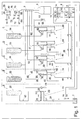
- the arrangement shown forms here Case a part of a drinks machine for filling or filling beverage bottles 3.
- the inventive method or the arrangement for Carrying out the method should on the one hand enable the user to bottle filled with different contents, for example 0.3 to 2 liters.
- the user should be informed about the composition of the drink, namely its You can largely determine the taste and, if necessary, its ingredients.
- Water is used as the main liquid in the present case, while as Auxiliary liquids, in particular sugar syrup, flavorings, colorings and valuable substances such as vitamins and fiber are provided.
- a hydraulic unit 1 To generate a hydraulic necessary for the operation of the arrangement Control pressure, a hydraulic unit 1 is provided. However, it is by no means mandatory that the hydraulic unit 1 is part of the arrangement, but this could just as well be arranged decentrally outside the arrangement. in the further two control devices 4, 11, a valve matrix 20, several system groups A, B, C, D, E for dosing various secondary liquids, supply lines 67, 72 for supplying main liquids, a supply line 76 for Supply of a gas and a mixing element 2 for mixing the main liquid (s) provided with the secondary liquids.
- Each system group is A, B, C, D, E. with a volumetrically operating, hydraulically operated conveying means 25, 34, 49, 54, 59 provided. Water is also used as the hydraulic medium in the present case used.
- the control devices 4, 11 each have one arranged in a cylinder 5, 12 Pistons 6, 13, which pistons 6, 13, based on the present drawing, can be moved to the left and to the right. Both control devices 4, 11 are hydraulically connected to the hydraulic unit 1 and for controlling the respective Pistons 6, 13 provided with a plurality of externally operated valves, wherein the corresponding lines and valves are not dealt with in detail, since their basic functionality is known.
- the two control devices 4, 11 are hydraulic via the valve matrix 20 with the system groups B, C, D, E connected. By means of this valve matrix 20, which in the present case actuated eight externally Includes valves, the system groups B, C, D, E can be hydraulically customized can be controlled, whereby two system groups are controlled simultaneously can be.
- Position sensor 8, 15 On the outside of the control devices 4, 11 there is one Position sensor 8, 15 arranged. Each displacement encoder 8, 15 is connected to a corresponding detection electronics 9, 16 connected. For example, on the magnetostrictive Principle working displacement sensors 8, 15 serve to detect the position of the piston 6, 13. To the on the primary side of the pistons 6, 13 of the control devices 4, To be able to influence the pressure acting there are two proportional valves 18, 19 intended. It goes without saying that control and detection electronics for actuation the components provided, such as the valves mentioned is. In addition, the control and detection electronics also serve to evaluate the signals emitted by sensors 8, 15. On the representation of this Control and detection electronics together with the associated electrical cables was omitted in favor of a clear presentation.
- the first system group A has a storage container 22 for receiving a first one Provide secondary liquid.
- the first secondary liquid made from sugar syrup.
- pump 23 is provided for the conveying means 25. That as a piston conveyor 25 trained funding is used for the exact metering of the first secondary liquid and forcibly supplying this first sub-liquid to the mixing element 2.
- the piston conveyor 25 is for this purpose with a cylinder 26 and an arranged therein Piston 27 displaceable in both directions.
- the right of the Piston 27 lying cylinder space 28 serves as a feed store for receiving the metered in Secondary fluid. Is on the outside of the piston conveyor 25 in turn a displacement sensor 29 is arranged on a corresponding detection electronics 30 is connected.
- This first system group A is via one line 31 connected to the mixing element 2.
- a cooling unit can be provided if necessary.
- Means for circulating those received in the storage container 22 can also be used Auxiliary fluid can be provided to ensure the homogeneity of this auxiliary fluid is guaranteed. However, the means mentioned are not shown in detail.
- the second system group B has one filled with a second secondary liquid Storage container 33 on. In contrast to the first system group A in this case however no pump is provided.
- the reservoir 33 is connected to the one Control devices 4, 11 actuated reciprocating piston conveyor 34 are provided.
- the reciprocating piston conveyor 34 has two pistons 35, 36 connected via a piston rod.
- the lower piston 35 will hereinafter be referred to as an actuating piston
- the upper piston 36 is referred to as a metering piston.
- the actuating piston 35 can be both upwards and downwards via the control devices 4, 11 be moved, the lines and valves provided for this purpose not closer are explained.
- the dosing space 37 arranged above the dosing piston 36 serves as a storage tank, by means of which the secondary liquid to be metered in is volumetric dosed and forcibly fed to the mixing element 2 via a line 46 can be.
- the mixing element through which the main liquid - water - flows 2 is used to mix the main liquid with the secondary liquids.
- the Valve matrix 20 enables the individual control of others, the individual System groups B, C, D, E assigned reciprocating piston conveyors 49, 54, 59. Both in the line 46 as well as in the connecting line between the reservoir 33 and the reciprocating piston conveyor 34 each have a check valve 38, 39 arranged on it however, their mode of action is also not discussed in detail.
- system group B has two hydraulic feed lines 40, 41 and two hydraulic feed lines Drain lines 42, 43 on.
- the other system groups C, D, E also each have a line 52, 57, 62 leading to the mixing element 2. These lines 52, 57, 62 open out at different points a mixing section into the mixing element 2 through which the main liquid flows.
- the beverage composition After the user has determined the beverage composition via an operating unit and the beverage bottle 3 has been placed at the intended location, it is checked for leaks by pressurizing the beverage bottle 3 via the line 76 and then determining whether the pressure is above a certain one Time period, for example a few seconds, remains constant or whether a maximum predetermined pressure drop is not exceeded.
- a gas such as nitrogen (N 2 ) or carbonic acid (CO 2 ) is preferably used for this density test as well as the subsequent prestressing of the beverage bottle 3.
- the size -content- of the beverage bottle is determined, for example by means of an optical sensor, or checked with any specification.
- a user interface control panel On the display of a user interface control panel, by means of which the user the beverage machine selects or compiles its beverage can, was waived.
- the composition the drink is menu-controlled by means of a "touch screen" that can be operated by the user Screen can be done.
- the user can, for example, determine the bottle size, the type and basis of the sweetener, the taste of the finished drink as well as any additives such as fiber and vitamins within determine certain limits yourself.
- the computer After the composition of the drink was determined, the computer is not shown Amount of the main and the individual secondary liquids calculated for the desired Total volume of the batch will be needed.
- the filling process is then started by supplying the main liquid via line 67 or 72.
- the CO 2 content can also be varied within wide limits.
- the supply of the secondary liquid or the secondary liquids is also started.
- the arrangement is designed such that both the delivery store for the first secondary liquid -cylinder space 28 of the piston conveyor 25- and the delivery store for the further secondary liquids -dosing cylinders 37, 50, 55, 60 of the reciprocating-piston conveyors 34, 49, 54, 59- are already in front are filled with the respective secondary liquid at the beginning of the filling process.
- the valve 24 is opened, whereby the piston 27 of the piston conveyor 25 is shifted to the right.
- the secondary liquid located in the metering cylinder 28 of the piston conveyor 25 is fed via line 31 to the mixing element 2, where it enters the interior thereof via a check valve and mixes with the main liquid flowing through.
- the further secondary liquid also becomes or the other secondary liquids are metered in.
- the secondary liquids can be arranged continuously or at intervals be fed.
- Such funding which works on the displacement principle, with volumetric Dosing is particularly useful when there are different secondary liquids promoted with at least partially different viscosities Need to become.
- 11 Valves can move both pistons 6, 13 for hydraulic Control of system groups B, C, D, E can be used.
- conveyor stores 37, 50, 55, 60 are provided, which are in relation can hold a very small amount of secondary liquid to the reservoir.
- the conveyor stores 37, 50, 55, 60 are preferably designed such that they Take up at least the maximum amount of secondary liquid to be added per batch can.
- the two control devices provided can be used controlled two reciprocating piston conveyors and thus two secondary liquids be metered in at the same time. It is understood that both the number of control devices as well as the number of reciprocating piston conveyors depending on the task can be changed at will.
- a membrane conveyor can also be used.
- Displacement principle working piston conveyor or reciprocating piston conveyor exists for one in that the secondary liquids can be metered in very precisely, there is no liquid slippage with such conveyors working on the displacement principle arises and the piston stroke is therefore directly proportional to the amount of metered Secondary fluid is.
- they can handle a relatively high delivery pressure be built up, which is higher than the system pressure by the mixing element main liquid is flowing.
- an accurate and reproducible dosage can from one or more secondary liquids, proportional to volume and time to one Main liquid, against increased, not constant pressure under tightened hygienic Requirements are met.
- Such an arrangement is suitable, for example also for dosing fiber and / or particle-containing secondary liquids.
- such an arrangement can be very easily above the two above the collection container 65 arranged valves 63, 64 are vented.
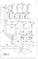
- Fig. 2 shows an alternative embodiment of an arrangement for metering from several secondary liquids to a flowing main liquid in a schematic Presentation.
- Such an arrangement is suitable, for example, for laboratory, medical or chemical applications in which the main liquid is preferably not under high pressure.
- the arrangement has a multiplicity of system groups 101, 103, 105, 107.
- Everyone System group 101, 103, 105, 107 is at least one storage container 110, 130, 150, 170, 171, 172, 173 assigned to absorb a secondary fluid.
- An example, seen from the left, is a container 110 for the first system group Holding a first secondary liquid, the second system group a container 130 a container for holding a second secondary liquid, the third system group 150 for receiving a third secondary liquid and the fourth system group several Containers 170, 171, 172, 173 assigned to hold additional secondary liquids.
- Each storage container 110, 130, 150, 170, 171, 172, 173 is with a buffer 111, 131, 151, 175, 176, 177, 178 connected, which before generating a batch is filled with the respective secondary liquid. Also in this case, the intermediate stores 111, 131, 151, 175, 176, 177, 178 are provided for a very small amount of secondary liquid in relation to the reservoir record, preferably again the maximum to be added per batch Amount of secondary fluid should be included. It is understood that the Number and arrangement of the storage containers 110, 130, 150, 170, 171, 172, 173 practically can be varied as arbitrarily as the type and quantity of those included Liquids.
- a vessel 102 provided for receiving the finished mixture is indicated drawn.
- a filling device is located above this vessel 102 104 arranged.
- the filling device 104 has a mixing valve 140, which via a line 141, 142, 143, 144 with the different system groups 101, 103, 105, 107 is connected.
- Main liquid can be supplied via a line 145 become.
- a Flow sensor 149 To be able to record the flow rate of the main liquid, if necessary, is a Flow sensor 149 provided.
- the buffer of the first system group is a cylindrical container 111 trained, the size of which is selected so that it at least that amount Can absorb secondary liquid, which is required for a maximum of one batch becomes.
- a compressor (not shown) is used to convey the first secondary liquid. provided, which via a line 112 to the reservoir 110 or a line 113 can be connected to the buffer 111.
- the second, third and fourth system groups are each via a common line 106 and a control valve 108 connected to a further supply line for main liquid.
- the buffer is in Formed a metering spiral 131, 151.
- a secondary liquid is a pump above the intermediate store 131, 151 132, 152 arranged.
- a drain valve 133, 153 is attached above the pump 132, 152, the function of which is explained below.
- a bypass line 135, 155 is provided to bypass the metering spiral 131, 151.
- To activate the drain valve 133, 153 of the bypass line 135, 155 and Filling and emptying the buffer 131, 151 are per system group 103, 105 three valves 136, 137, 138; 156, 157, 158 are provided.
- the fourth system group 107 is provided with a total of four storage containers 170, 171, 172, 173 to accommodate generic liquids of the same type.
- Any storage container 170, 171, 172, 173 is a buffer in the form of a metering spiral 175, 176, 177, 178 assigned.
- there is only one pump 180 for pumping one auxiliary liquid per batch is provided.
- All inlets and outlets the metering spirals 175, 176, 177, 178 are each via a common line 181, 182 connected.
- This system group 107 also has a bypass line 183 to bypass the metering spirals 175, 176, 177, 178 and a drain valve 184 provided.
- a plurality of valves is provided, but not in detail is received.
- 3a to 3d show the first system group 101 in different phases during Add a first secondary liquid. From these representations it can be seen that this system group 101 together with the storage container 110 and the buffer store 111, a ventilation device 114, a control device 115, a Level sensor 117, a first pneumatic control valve 118, a second pneumatic Control valve 120 and various other valves.
- FIG. 3a shows the system group 101 at the beginning of the metering process.
- the one with the first secondary liquid filled buffer 111 is via the open pressure control valve 118 connected to the source of positive pressure.
- the buffer is available 111 under pressure and is forcibly emptied.
- the control device 115 is provided, which is connected to the pressure control valve 118.
- the capacitive level sensor 117 is connected, via which the Decrease in secondary liquid per unit of time recorded and by means of the control device 115 can be kept at a predetermined value.
- the decrease Secondary fluid per unit of time corresponds directly to that of the main fluid per unit of time amount of secondary liquid added.
- the amount to be added per unit time depends Amount of first secondary liquid depends on several parameters. On the one hand the flow rate of the main liquid must be taken into account. On the other hand it depends on the desired ratio between the main liquid and Secondary fluid.
- 3b shows the state of the system group 101 towards the end of the metering process.
- 3c shows the system group 101 in a snapshot when filling of the buffer 111 can be seen.
- the valve 123 at the outlet of the Buffer 111 switched to pass while intake valve 124 was switched to lock, so that the buffer 111 over the line 126 is connected to the reservoir 110 and from this again with secondary liquid can be replenished.
- the reservoir 110 is under positive pressure set so that the first secondary liquid is forcibly in the buffer 111 is directed.
- the ventilation device 114 the flow through the Secondary liquid displaced air escape from the intermediate storage 111.
- Fig. 3d the system group is shown in the starting position, in which the Buffer 111 is again filled with the first secondary liquid and for a next batch is ready.
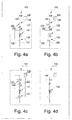
- 4a to 4d show the second system group 103 in different phases when adding a second secondary liquid.
- Pump 132 is through the input actuator 108 connected to the main liquid source.
- the pump 132 is not from the by-liquid is flowed through, but that an overpressure or underpressure exerted by the pump 132 Transfer to the secondary liquid via the mediating medium -water , and a filling or emptying of the buffer memory 131 is effected.
- the two media can be water and secondary liquid can be separated, for example by means of an air bubble. The Means for generating an air bubble are not shown in detail.
- FIG. 4a shows the system group 103 in the starting position, in which the metering spiral 131 is filled with secondary liquid.
- the emptying of the metering spiral 131 takes place by activating the pump 132.
- the mediating medium transmits the pressure difference built up by the pump 132 to that in the metering spiral 131 absorbed secondary fluid.
- the delivery rate of the pump 132 is by means of regulated electronics not shown here. If a reciprocating pump is used, the addition of the second can be done via the number of strokes per time Auxiliary fluid can be controlled. However, a regulation is also conceivable in which the fill level of the metering spiral 131 is measured and used as the actual value.
- main liquid in the present case water.
- This turns the metering spiral 131 into a mixing valve leading line 142 rinsed with water and residual liquid residues exempted.
- This rinsing is particularly important if the Dosing spiral 131 to the mixing valve line 142 various secondary liquids can be supplied, such as in the fourth system group 107 (Fig. 2) is possible.
- This rinsing process is designed so that the Line 142 completely of the secondary liquid used for the corresponding batch was liberated, however, care is taken that ultimately only one very small amount of rinsing liquid gets into the vessel 102.
- FIG. 4c shows the system group when filling the metering spiral 131 first the two valves 137, 138 switched over and the drain valve 133 open.
- a vacuum is now generated by means of the pump 132, so that the second Secondary liquid is sucked from the reservoir 130 into the metering spiral 131.
- the maximum fill level of the metering spiral 131 can be reached, for example, by means of an optical sensor can be monitored. Via the open drain valve 133 both parts of the line can be vented and residual liquid can be drained off.
- the system group 103 is shown in the starting position, in which the metering spiral 131 is in turn filled with the second secondary liquid.
- the arrangements described above provide maximum flexibility achieved in terms of the possible composition of the final product.
- the second embodiment provides a simpler, cheaper Variant, which is particularly suitable for metering in secondary liquids to one that is not or only under a slight positive pressure Main liquid is suitable.
- the second embodiment is particularly suitable also for dosing very small amounts of secondary liquids.
Landscapes
- Chemical & Material Sciences (AREA)
- Chemical Kinetics & Catalysis (AREA)
- Engineering & Computer Science (AREA)
- Mechanical Engineering (AREA)
- Accessories For Mixers (AREA)
- Non-Alcoholic Beverages (AREA)
Applications Claiming Priority (2)
| Application Number | Priority Date | Filing Date | Title |
|---|---|---|---|
| CH3612000 | 2000-02-24 | ||
| CH3612000 | 2000-02-24 |
Publications (1)
| Publication Number | Publication Date |
|---|---|
| EP1132337A1 true EP1132337A1 (fr) | 2001-09-12 |
Family
ID=4512890
Family Applications (1)
| Application Number | Title | Priority Date | Filing Date |
|---|---|---|---|
| EP01810088A Withdrawn EP1132337A1 (fr) | 2000-02-24 | 2001-01-30 | Méthode et dispositif pour mélanger des liquides |
Country Status (3)
| Country | Link |
|---|---|
| US (1) | US20010017815A1 (fr) |
| EP (1) | EP1132337A1 (fr) |
| JP (1) | JP2001269562A (fr) |
Cited By (7)
| Publication number | Priority date | Publication date | Assignee | Title |
|---|---|---|---|---|
| WO2008112414A3 (fr) * | 2007-03-15 | 2009-03-26 | Coca Cola Co | Système de remplissage de courant multiple |
| EP2388064A1 (fr) * | 2010-05-19 | 2011-11-23 | Krones AG | Dispositif et procédé destinés au mélange de boissons |
| CN102889190A (zh) * | 2012-10-24 | 2013-01-23 | 徐州五洋科技股份有限公司 | 一种可自动配制乳化液的矿用乳化液泵 |
| FR3012123A1 (fr) * | 2013-10-18 | 2015-04-24 | Heineken Entpr | Dispositif de distribution d'une boisson permettant l'injection d'au moins un additif dans la boisson distribuee |
| US9394153B2 (en) | 2007-03-15 | 2016-07-19 | The Coca-Cola Company | Multiple stream filling system |
| US9865023B2 (en) | 2008-02-04 | 2018-01-09 | The Coca-Cola Company | Methods of creating customized beverage products |
| CN114671410A (zh) * | 2020-12-24 | 2022-06-28 | 大连理工江苏研究院有限公司 | 一种稳定剂的添加系统 |
Families Citing this family (20)
| Publication number | Priority date | Publication date | Assignee | Title |
|---|---|---|---|---|
| US10631558B2 (en) | 2006-03-06 | 2020-04-28 | The Coca-Cola Company | Methods and apparatuses for making compositions comprising an acid and an acid degradable component and/or compositions comprising a plurality of selectable components |
| US9821992B2 (en) | 2006-03-06 | 2017-11-21 | The Coca-Cola Company | Juice dispensing system |
| US8046976B2 (en) * | 2006-07-25 | 2011-11-01 | The Coca-Cola Company | Devices and methods for packaging beverages |
| US8162176B2 (en) | 2007-09-06 | 2012-04-24 | The Coca-Cola Company | Method and apparatuses for providing a selectable beverage |
| US8746506B2 (en) | 2011-05-26 | 2014-06-10 | Pepsico, Inc. | Multi-tower modular dispensing system |
| US8985396B2 (en) | 2011-05-26 | 2015-03-24 | Pepsico. Inc. | Modular dispensing system |
| US10549248B2 (en) | 2015-04-23 | 2020-02-04 | B. Braun Medical Inc. | Compounding device system, software and method for controlling the process of compounding admixtures |
| US9815683B1 (en) | 2016-10-11 | 2017-11-14 | Fuel Automation Station, LLC | Method and system for mobile distribution station |
| US10087065B2 (en) | 2016-10-11 | 2018-10-02 | Fuel Automation Station, LLC | Mobile distribution station having sensor communication lines routed with hoses |
| US9586805B1 (en) | 2016-10-11 | 2017-03-07 | Fuel Automation Station, LLC | Mobile distribution station with aisle walkway |
| US9790080B1 (en) | 2016-10-11 | 2017-10-17 | Fuel Automation Station, LLC | Mobile distribution station with fail-safes |
| US10289126B2 (en) | 2016-10-11 | 2019-05-14 | Fuel Automation Station, LLC | Mobile distribution station with guided wave radar fuel level sensors |
| US10633243B2 (en) | 2017-02-24 | 2020-04-28 | Fuel Automation Station, Llc. | Mobile distribution station |
| DE102017120324A1 (de) * | 2017-09-04 | 2019-03-07 | Krones Ag | Vorrichtung und Verfahren zum Befüllen eines Behälters mit einem Füllprodukt |
| US10150662B1 (en) | 2017-10-27 | 2018-12-11 | Fuel Automation Station, Llc. | Mobile distribution station with additive injector |
| US10926996B2 (en) | 2018-05-04 | 2021-02-23 | Fuel Automation Station, Llc. | Mobile distribution station having adjustable feed network |
| CA3051985C (fr) | 2018-08-24 | 2022-08-09 | Fuel Automation Station, LLC | Station de distribution mobile avec antenne parabolique |
| US11142449B2 (en) | 2020-01-02 | 2021-10-12 | Fuel Automation Station, LLC | Method and system for dispensing fuel using side-diverting fuel outlets |
| US11827421B2 (en) | 2020-01-17 | 2023-11-28 | Fuel Automation Station, LLC | Fuel cap assembly with cylindrical coupler |
| US20230235270A1 (en) * | 2020-06-26 | 2023-07-27 | Astraveus | Device for homogenization of a multicomponent fluid |
Citations (7)
| Publication number | Priority date | Publication date | Assignee | Title |
|---|---|---|---|---|
| US2736466A (en) * | 1950-10-11 | 1956-02-28 | Joseph J Rodth | Liquid metering and dispensing device |
| EP0152283A2 (fr) | 1984-02-09 | 1985-08-21 | Raymond Dixon | Distribution de boissons |
| WO1990002702A1 (fr) | 1988-09-16 | 1990-03-22 | Milton Roy Company | Distributeur de boissons |
| EP0443837A2 (fr) | 1990-02-20 | 1991-08-28 | Micro-Blend, Inc. | Appareil et méthode de mélange et dosage de boissons |
| EP0479113A1 (fr) | 1990-10-05 | 1992-04-08 | ALFILL GETRÄNKETECHNIK GmbH | Dispositif pour préparer des boissons |
| EP0664086A1 (fr) * | 1993-12-21 | 1995-07-26 | Manfred Dr.-Ing. Mette | Procédé et dispositif pour préparer des boissons à partir de plusieurs composants coulants |
| US5996907A (en) * | 1998-03-02 | 1999-12-07 | Ecolab Inc. | Portable wash and rinse system with dilution |
-
2001
- 2001-01-30 EP EP01810088A patent/EP1132337A1/fr not_active Withdrawn
- 2001-02-13 US US09/782,211 patent/US20010017815A1/en not_active Abandoned
- 2001-02-26 JP JP2001049977A patent/JP2001269562A/ja active Pending
Patent Citations (7)
| Publication number | Priority date | Publication date | Assignee | Title |
|---|---|---|---|---|
| US2736466A (en) * | 1950-10-11 | 1956-02-28 | Joseph J Rodth | Liquid metering and dispensing device |
| EP0152283A2 (fr) | 1984-02-09 | 1985-08-21 | Raymond Dixon | Distribution de boissons |
| WO1990002702A1 (fr) | 1988-09-16 | 1990-03-22 | Milton Roy Company | Distributeur de boissons |
| EP0443837A2 (fr) | 1990-02-20 | 1991-08-28 | Micro-Blend, Inc. | Appareil et méthode de mélange et dosage de boissons |
| EP0479113A1 (fr) | 1990-10-05 | 1992-04-08 | ALFILL GETRÄNKETECHNIK GmbH | Dispositif pour préparer des boissons |
| EP0664086A1 (fr) * | 1993-12-21 | 1995-07-26 | Manfred Dr.-Ing. Mette | Procédé et dispositif pour préparer des boissons à partir de plusieurs composants coulants |
| US5996907A (en) * | 1998-03-02 | 1999-12-07 | Ecolab Inc. | Portable wash and rinse system with dilution |
Cited By (13)
| Publication number | Priority date | Publication date | Assignee | Title |
|---|---|---|---|---|
| US9394153B2 (en) | 2007-03-15 | 2016-07-19 | The Coca-Cola Company | Multiple stream filling system |
| AU2008226673B2 (en) * | 2007-03-15 | 2012-07-05 | The Coca-Cola Company | Multiple stream filling system |
| WO2008112414A3 (fr) * | 2007-03-15 | 2009-03-26 | Coca Cola Co | Système de remplissage de courant multiple |
| US8479784B2 (en) | 2007-03-15 | 2013-07-09 | The Coca-Cola Company | Multiple stream filling system |
| US10099911B2 (en) | 2007-03-15 | 2018-10-16 | The Coca-Cola Company | Multiple stream filling system |
| US9865023B2 (en) | 2008-02-04 | 2018-01-09 | The Coca-Cola Company | Methods of creating customized beverage products |
| EP2388064A1 (fr) * | 2010-05-19 | 2011-11-23 | Krones AG | Dispositif et procédé destinés au mélange de boissons |
| CN102889190A (zh) * | 2012-10-24 | 2013-01-23 | 徐州五洋科技股份有限公司 | 一种可自动配制乳化液的矿用乳化液泵 |
| CN102889190B (zh) * | 2012-10-24 | 2016-01-20 | 徐州五洋科技股份有限公司 | 一种可自动配制乳化液的矿用乳化液泵 |
| EP2891622A1 (fr) * | 2013-10-18 | 2015-07-08 | Heineken Entreprise | Dispositif de distribution d'une boisson permettant l'injection d'au moins un additif dans la boisson distribuée |
| FR3012123A1 (fr) * | 2013-10-18 | 2015-04-24 | Heineken Entpr | Dispositif de distribution d'une boisson permettant l'injection d'au moins un additif dans la boisson distribuee |
| CN114671410A (zh) * | 2020-12-24 | 2022-06-28 | 大连理工江苏研究院有限公司 | 一种稳定剂的添加系统 |
| CN114671410B (zh) * | 2020-12-24 | 2023-06-09 | 大连理工江苏研究院有限公司 | 一种稳定剂的添加系统 |
Also Published As
| Publication number | Publication date |
|---|---|
| US20010017815A1 (en) | 2001-08-30 |
| JP2001269562A (ja) | 2001-10-02 |
Similar Documents
| Publication | Publication Date | Title |
|---|---|---|
| DE60304002T2 (de) | Automatisiertes System und Verfahren zum Herstellen von hochviskosen Flüssigkeitsrezepturen | |
| DE60017373T2 (de) | Präzisions-abgabevorrichtung für flüssigkeiten | |
| DE69826804T2 (de) | Flüssigkeitsverteilvorrichtung und Verfahren | |
| DE1904014B2 (de) | Vorrichtung zum kontinuierlichen Ver einigen von Getrankekomponenten in ein stellbarem Mengenverhältnis | |
| US20010017815A1 (en) | Method and an assembly for the batchwise preparation of a liquid product | |
| DE69914684T2 (de) | Verfahren und Vorrichtung zum Abfüllen unter Schwerkraft von Flüssigkeiten in Behälter | |
| CH703127A1 (de) | Dispenser und Verfahren zum Abgeben von fliess- oder rieselfähigen Materialien. | |
| EP1065948A1 (fr) | Dispositif permettant de preparer en continu au moins deux melanges constitues d'aliments liquides differents | |
| CH685746A5 (de) | Vorrichtung zum Befüllen einer oder mehrerer Giessformen mit fliessfähigen Stoffen. | |
| EP0793566B1 (fr) | Dispositif permettant d'acheminer de maniere dosee des constituants individuels de plastique liquide a plusieurs constituants jusqu'a une tete melangeuse | |
| DE102020130740A1 (de) | Vorrichtung zum Befüllen eines Behälters mit einem Füllprodukt | |
| DE19709603C2 (de) | Verfahren und Vorrichtung zur Serienkultivierung von Organismen | |
| EP0366997B1 (fr) | Procédé pour désaérer une installation de remplissage et dispositif pour la mise en oeuvre du procédé | |
| DE4206728A1 (de) | Verfahren zur zubereitung, zufuehrung und ausbringung pumpfaehiger viehfuttermischungen an verbraucherstellen und einrichtung zur durchfuehrung des verfahrens | |
| DE4106619C2 (de) | Verfahren zum Einbringen einer Zumischung, insbesondere von Früchten und/oder Fruchtteilen als Fruchtzubereitung, in eine flüssige Grundsubstanz, insbesondere Joghurt, und zum anschließenden Abfüllen der entstandenen Mischung in Behälter, insbesondere Becher, sowie Vorrichtung zur Ausführung des Verfahrens | |
| DE102011009076B3 (de) | Tränkeautomat zum Füttern von Jungtieren, wie Ferkel und Kälber, mit Flüssignahrung, Vorrichtung mit selbigem sowie Verfahren zum Überwachen und bedarfsweisen Kalibrieren der Dosierung von einer oder mehreren Pulverkomponente(n) einer Flüssignahrung | |
| DE19824057C1 (de) | Verfahren und Vorrichtung zur Versorgung einer Dialysevorrichtung mit Dialysierflüssigkeit oder Dialysierflüssigkeitskonzentrat | |
| DE69532920T2 (de) | Vorrichtung zur volumetrischen Abgabe von Flüssigkeiten | |
| EP1884466B1 (fr) | Installation de remplissage pour masse coulante | |
| EP3861416B1 (fr) | Système d'éjection de liquide pour une installation de lavage de véhicules et son procédé de fonctionnement | |
| DE2220224B1 (de) | Verfahren zur Herstellung von Flüssigkeitsgemischen vorgegebener Zusammensetzung | |
| DE3243319A1 (de) | Verfahren und anordnung zum wahlweisen portionsmaessigen oder kontinuierlichen abgeben und mischen von unterschiedlichen fluessigkeiten in genauen mengen und mengenanteilen unabhaengig von schwankungen der viskositaet und/oder eines etwaigen vor- oder fliessdruckes | |
| EP4105615B1 (fr) | Procédé de dosage pour unités posologiques et utilisation d'une vanne doseuse dans un dispositif d'étalonnage pour un système de mesure capacitif | |
| DE102011084720A1 (de) | Mixer für Pulpe- und Faserhaltige Getränke | |
| DE102018122062B4 (de) | Vorrichtung und Verfahren zum Befüllen von Behältern mit einem flüssigen Füllgut |
Legal Events
| Date | Code | Title | Description |
|---|---|---|---|
| PUAI | Public reference made under article 153(3) epc to a published international application that has entered the european phase |
Free format text: ORIGINAL CODE: 0009012 |
|
| AK | Designated contracting states |
Kind code of ref document: A1 Designated state(s): AT BE CH CY DE DK ES FI FR GB GR IE IT LI LU MC NL PT SE TR |
|
| AX | Request for extension of the european patent |
Free format text: AL;LT;LV;MK;RO;SI |
|
| 17P | Request for examination filed |
Effective date: 20011102 |
|
| 17Q | First examination report despatched |
Effective date: 20020128 |
|
| AKX | Designation fees paid |
Free format text: AT BE CH CY DE DK ES FI FR GB GR IE IT LI LU MC NL PT SE TR |
|
| STAA | Information on the status of an ep patent application or granted ep patent |
Free format text: STATUS: THE APPLICATION IS DEEMED TO BE WITHDRAWN |
|
| 18D | Application deemed to be withdrawn |
Effective date: 20020807 |