EP1132537A2 - Halterung für Verglasungs- oder sonstige Fassadenelemente - Google Patents
Halterung für Verglasungs- oder sonstige Fassadenelemente Download PDFInfo
- Publication number
- EP1132537A2 EP1132537A2 EP01105218A EP01105218A EP1132537A2 EP 1132537 A2 EP1132537 A2 EP 1132537A2 EP 01105218 A EP01105218 A EP 01105218A EP 01105218 A EP01105218 A EP 01105218A EP 1132537 A2 EP1132537 A2 EP 1132537A2
- Authority
- EP
- European Patent Office
- Prior art keywords
- profile piece
- elements
- glazing
- profile
- substructure
- Prior art date
- Legal status (The legal status is an assumption and is not a legal conclusion. Google has not performed a legal analysis and makes no representation as to the accuracy of the status listed.)
- Withdrawn
Links
Images



Classifications
-
- E—FIXED CONSTRUCTIONS
- E04—BUILDING
- E04F—FINISHING WORK ON BUILDINGS, e.g. STAIRS, FLOORS
- E04F13/00—Coverings or linings, e.g. for walls or ceilings
- E04F13/07—Coverings or linings, e.g. for walls or ceilings composed of covering or lining elements; Sub-structures therefor; Fastening means therefor
- E04F13/08—Coverings or linings, e.g. for walls or ceilings composed of covering or lining elements; Sub-structures therefor; Fastening means therefor composed of a plurality of similar covering or lining elements
- E04F13/0801—Separate fastening elements
- E04F13/0803—Separate fastening elements with load-supporting elongated furring elements between wall and covering elements
- E04F13/081—Separate fastening elements with load-supporting elongated furring elements between wall and covering elements with additional fastening elements between furring elements and covering elements
- E04F13/0814—Separate fastening elements with load-supporting elongated furring elements between wall and covering elements with additional fastening elements between furring elements and covering elements fixed by means of clamping action
-
- E—FIXED CONSTRUCTIONS
- E04—BUILDING
- E04B—GENERAL BUILDING CONSTRUCTIONS; WALLS, e.g. PARTITIONS; ROOFS; FLOORS; CEILINGS; INSULATION OR OTHER PROTECTION OF BUILDINGS
- E04B2/00—Walls, e.g. partitions, for buildings; Wall construction with regard to insulation; Connections specially adapted to walls
- E04B2/88—Curtain walls
- E04B2/96—Curtain walls comprising panels attached to the structure through mullions or transoms
- E04B2/967—Details of the cross-section of the mullions or transoms
-
- E—FIXED CONSTRUCTIONS
- E04—BUILDING
- E04F—FINISHING WORK ON BUILDINGS, e.g. STAIRS, FLOORS
- E04F13/00—Coverings or linings, e.g. for walls or ceilings
- E04F13/07—Coverings or linings, e.g. for walls or ceilings composed of covering or lining elements; Sub-structures therefor; Fastening means therefor
- E04F13/08—Coverings or linings, e.g. for walls or ceilings composed of covering or lining elements; Sub-structures therefor; Fastening means therefor composed of a plurality of similar covering or lining elements
- E04F13/0801—Separate fastening elements
- E04F13/0803—Separate fastening elements with load-supporting elongated furring elements between wall and covering elements
- E04F13/081—Separate fastening elements with load-supporting elongated furring elements between wall and covering elements with additional fastening elements between furring elements and covering elements
- E04F13/0821—Separate fastening elements with load-supporting elongated furring elements between wall and covering elements with additional fastening elements between furring elements and covering elements the additional fastening elements located in-between two adjacent covering elements
Definitions
- the invention relates to a holder for glazing or other facade elements on an optionally Substructure consisting of post profiles and transom profiles. Whether this substructure Metal hollow or solid profiles or wooden beams, it always requires a corresponding one Bracket for fixing the glazing or other facade elements. Such facades are generally referred to as warm facades in buildings. Between the substructure and the Glazing or other facade elements are arranged profile elements, which as a rule Have grooves to accommodate seals. In a known device of this type (DE 94 14 887 U1) a profile tube with an elongated projection is provided on the substructure which is then put on a one-piece insulating profile made of plastic.
- the present invention has for its object to a bracket of the type mentioned create with the optimal fastening of the profile elements facing the substructure, the glazing or other facade elements and also a preliminary fixation of the glazing or other Facade elements is made possible without the end profiles already having to be fastened.
- this is achieved by means of a strip-shaped profile piece with a plurality of transverse to it Longitudinal through holes and / or blind holes for inserting fasteners for fixing the profile piece to the substructure, for fixing holding tabs when installing the glazing or other facade elements and for fixing the Edges of the glazing or other facade elements overlapping end profiles.
- the end profiles can be installed in a simple manner by namely, the fasteners provided there also again in already prepared through Engage holes and / or blind holes in the profile piece or several profile pieces can.
- the height of the profile piece approximately the thickness of the glazing or other Facade elements plus the thickness of those provided between them and the substructure Corresponds to profile elements.
- the profile piece also acts practically as between adjacent glazing or other facade elements used bar, in which depending on the need or Blocking elements are used on both sides. It is of course a correspondingly long one Intervention of the fasteners to be used possible, since their length must be coordinated that there is sufficient intervention, but not too much penetration is required.
- the profile piece to adapt to different thick glazing or other facade elements in different or any height range is separable. Because the one holes go through the entire height of the profile piece and the Blind holes have a sufficient depth, the profile pieces can have different thicknesses Glazing or other facade elements can be adjusted. It is also conceivable to use different ones Notches or imprints to provide different heights of the profile pieces define. If heights are required more than once, there will also be the possibility from the outset prefabricate different heights of profile pieces.
- the profile piece have two or more through holes for insertion of fasteners for fixing the profile piece to the substructure. Two holes are therefore at least provided, since this will inadvertently twist the profile piece is excluded. But it is precisely because of this that the profile piece is optimally fastened possible together with the profile elements usually resting on the substructure. Especially for this attachment can be made by designing the through holes accordingly Fastener of relatively large dimensions are used, thereby freeing the strength cantilevered area of the profile pieces is specified.
- the profile piece has two or more continuous Bores and / or blind holes for inserting fasteners for fixation of retaining tabs when installing the glazing or other facade elements and for the fixing of the end profiles overlapping the edges of the glazing or other facade elements having.
- Another embodiment variant provides that the profile piece at a distance from its one, in the assembly position substructure-side limitation on both sides preferably over the entire length of the same has continuous web. On the one hand, through this web after assembly by the fasteners optimum retention of the profile elements assigned to the substructure can be achieved, on the other hand, this results in a firm stop for the glazing or others to be used Facade elements.
- the webs of the profile piece on one or both sides in Transition area to the profile piece have a groove-like undercut.
- it can for the corresponding edge of the glazing or other facade element and on the other hand for Edge areas of the underlying profile elements are exempted so that unnecessary tensions can be avoided.
- a possible embodiment variant is that the webs of the profile piece approximately circular in cross-section except for the direct transition to the profile piece are rectangular with rounded corners. This will make the contact surface of the webs both in the area of glazing or other facade elements as well as in the area below lying profile elements limited to a necessary minimum.
- the profile piece on its substructure side in the installed position Limitation in the area of the continuous for attachment to the substructure Bores ring-shaped protruding approaches for centering in pre-drilled holes in the between the substructure and the glazing or other facade elements used profile elements having. This ensures that the profile piece is always in the exact desired orientation and in the desired height or side position together with the corresponding profile elements on Substructure is attached. It is therefore also a corresponding factory pre-processing of the Profile elements assigned to the substructure possible.
- the special design also proves the retaining tab is particularly advantageous because of the mutual interaction between the profile piece and mounting bracket in terms of both assembly and safety with regard to the required Bracket to get the most out of it. It is therefore proposed that the retaining tabs on both sides next to a hole for receiving a fastener in the assembled state in the Have recesses on the profile engaging extensions, the extensions in cross section at least approximately U-shaped and are directed towards each other with their open sides. A material-saving construction is thus created and nevertheless an extraordinary one Stiffness of these extensions. This is also advantageous because e.g.
- Another advantageous embodiment of the invention is that the two end regions of the profile piece facing in the same order in the longitudinal direction of the same seen a continuous Hole for inserting fasteners for fixing the profile piece to the substructure and a blind hole for inserting fasteners for fixing the edges of the Glazing or other facade elements overlapping end profiles follow one another, the immediately successive through holes and the blind holes each have the same distance from each other. It is therefore possible in a simple manner, both the to prepare the profile elements assigned to the substructure and the end profiles at the factory, that is already provided with the appropriate holes.
- the profile piece is made of plastic is, in addition to the simple assembly and secure mounting for glazing or other Facade elements also enable optimal thermal separation.
- An invention The intended profile piece has sufficient strength, even if it is made of a plastic is made.
- the fastening elements and used for fastening the profile piece to the substructure the fasteners for the retaining tabs and for the end profiles do not come in any way in contact with each other, since these are located in mutually parallel bores of the Intervene in the profile piece. A clean thermal separation is therefore possible, so that from a spoken in terms of assembly technology and safety as well as thermally optimal warm facade can be.
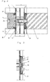
- glazing elements 1 are on a substructure 2 attached, which may consist of vertical post profiles and horizontal transom profiles.
- This substructure 2 can consist of solid or hollow profiles made of metal or, if appropriate, also Plastic or wooden beams or slats.
- a simple and quick assembly should be possible. It also becomes more special Accurate thermal separation is important, in order to prevent heat or cold bridges avoid.
- the holder according to the present invention is essentially due to a specially designed Profile piece 3, which is formed strip-shaped, such profile pieces 3 with a corresponding Can be attached to the substructure 2 in succession. These profile pieces 3 then serve also for fastening the glazing elements 1 used and finally for fixing the the edges of the glazing elements 1 overlapping end profiles 4th
- the essential feature of the profile piece 3 is that it has a variety of transverse to it Longitudinal through holes 5 and blind holes 6 and 7, which each is of particular importance. It would be quite conceivable to replace blind holes 6 and 7 instead through holes must also be provided for this area.
- the height H of the profile piece 3 corresponds approximately to the thickness D of the glazing elements 1 plus the thickness P of the profile elements provided between these glazing elements 1 and the substructure 2 8 and 9.
- the width B of the profile piece 3 corresponds approximately to the distance A adjacent Glazing elements 1 minus that between the profile piece 3 and the edge of the glazing elements Blocking elements to be used 10.
- the profile piece 3 can be of different lengths H1, H2 and H3 are separated. Here it is either an arbitrary separation to an arbitrary dimension possible, or there are notches or printed dimensions, along which then separation can take place.
- the profile piece 3 is adapted to the most common Thickness D of the glazing elements 1 also in different dimensions of the height H from the outset are manufactured.
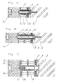
- the bores 5 are continuous and are used for inserting screws Fasteners 11, such as 13 and 14 can also be seen.
- This Bores 5 also have a correspondingly larger diameter in order to have a larger cross section To be able to accommodate fasteners 11. Bring the fasteners 11 used here so to speak, also the stable alignment of the profile pieces 3 with respect to the substructure 2.
- the holes 7 are used to fix the retaining tabs 12, which after inserting the glazing elements 1 overlap the edge area of the same. Both sides of the blind holes 7 are immediate formed on the full material essentially axially parallel to the blind hole 7 Recesses 14 and 15 are provided, in which recesses 14, 15 on the retaining tab 12 trained extensions 16 and 17 engage. It is envisaged that these recesses 14, 15 at the same distance X from the central axis of the blind hole 7 in parallel have boundaries 18, 19 aligned with one another. With appropriate design of the extensions 16 and 17 can practically be a kind of fit when inserting the retaining tabs 12.
- the retaining tab 12 is on both sides next to the Bore 20 for receiving the fastening element 21 has corresponding extensions 16, 17, these extensions 16, 17 are advantageously U-shaped in cross section. These extensions 16 and 17 are arranged so that their U cross section with the open side against each other is directed. Especially in configurations where the height H of the profile piece 3 is too small, if - as shown in Fig. 13 - between the freely projecting edge of the profile piece 3 and the a distance C remains at the foremost front of the glazing elements 1, these cause a special one Extensions 16, 17 having rigidity provide a stable and non-rotatable mounting of the Glazing elements through the retaining tabs 12.
- these extensions 16 and 17 could also be used as in cross section, for example, rectangular full profiles or solid profiles or hollow profiles in another cross-section, but then despite a hardly increasing stiffness with one to expect a larger proportion of material.
- Recesses 14, 15 are arranged in succession in the longitudinal direction of the profile piece 3. It can then practically immediately successively holding tabs 12 in on a profile piece 3 Direction to one and towards the other of two adjacent glazing elements to be used in an instructive manner.
- two or more blind holes 6 are also provided in the profile piece 3, which for the fixation of the edges of the glazing elements 1 overlapping end profiles 4 serve. 4 and 8 that the two end regions of the profile piece 3 facing in the same order in the longitudinal direction of the same seen a through hole 5 for inserting fastening elements 11 (see FIGS. 11 and 12) for fixing the profile piece 3 on the base 2 and a blind hole 6 for inserting fastening elements 22 for fixing the end profiles 4 overlapping the edges of the glazing elements 1 consequences.
- the immediately successive through holes 5 and the blind holes 6 each have the same distance E from one another.
- the profile piece 3 also has a distance F from its one, in the mounting position, substructure-side limitation a web 24, preferably continuous, over the entire length of the web on both sides.
- a web 24 preferably continuous, over the entire length of the web on both sides.
- the webs 24 in Cross section up to the immediate transition to the profile piece 3 in cross section approximately circular or be rectangular with rounded corners.
- the profile elements 8 and the end profiles 4 are very simple Can be predrilled in a way that is precisely coordinated with one another, so that a quick and easy and above all accurate assembly is made possible.
- the profile element 8 and that End profile 4 have coordinated dimensions, so that thereby an optimal Prefabrication can be achieved with the holes.
- a construction is required in which the Profile element 8 and the end profile 4 aligned transversely to their longitudinal extent against each other can be held, although a mutual displacement in the longitudinal direction must be made possible.
- the end profile 4 lateral boundary webs 27 are provided, their free distance G also corresponds to the width of the profile element 8.
- the profile element 8 can can be inserted practically in the longitudinal direction into the end profile 4.
- dimension E is the distance between the holes 5 and 6 in the profile piece 3, in the longitudinal direction of each other, as shown in FIG. 16 can be seen.
- dimension E is the distance between the holes 5 and 6 in the profile piece 3, in the longitudinal direction of each other, as shown in FIG. 16 can be seen.
- a step drill 28 is used for the production of the holes in the profile element 8 and in the End profile 4 made a hole, for which purpose a step drill 28 is used.
- the hole in the profile element 8 must yes for the use of the annular extension 26 of the profile pieces be designed accordingly larger.
- the holes through the two walls 29 and 30 of the End profile 4 are smaller in diameter because they are only for the passage of the fastener 22 must be large enough. If, on the other hand, as corresponding to FIG.
- the step drill 28 is screwed in further, so that in the Wall 30 is prepared a correspondingly larger hole. Because the two pre-drilled profiles in the longitudinal direction by the dimension E of the distance between the holes 5 and 6 in the profile piece 3 staggered to each other results in the final assembly of the whole Bracket an exact alignment of the prepared holes in relation to the use of the Fastening elements 11 for fixing to the substructure and for using the fastening elements 22 for fixing the end profiles 4 with respect to the profile piece 3. Are in the final position So the holes made with a single step drill 28 are in turn offset by dimension E. arranged to each other, so that an accurate and above all problem-free assembly is made possible.
- the profile piece 3 can be made of metal or plastic. When manufacturing from metal execution with a die casting is also possible. However, the most advantageous embodiment is the production from plastic, because then optimal thermal separation without formation can be reached from cold or thermal bridges.
- the fasteners 11, 22 used and 21 are arranged next to each other with a corresponding distance, so that no direct There is a connection with metallic elements from the outside to the substructure.
- a nose 32 serves to compensate for tolerances when inserting the profile piece 3 into the groove 33 formed on the profile element 8.
- the required holes in the profile elements 8 and the end profiles can already 4 are provided, namely according to that explained with reference to FIGS. 16 and 17 in the description Procedure.
- the profile elements 8 and 9 are then placed on the base 2, the Profile element 9 can consist of plastic or an elastic material. It would be too conceivable, here only in corresponding recesses of the profile element 8 seals or the like to use.
- Profile pieces 3 are now used at predetermined intervals, these have an exact position because they are in the prepared holes on the profile element by means of the lugs 26 8 can intervene.
- the fasteners 11 see Fig. 11 and 12
- the profile piece 3 By screwing the fasteners 11 (see Fig. 11 and 12) attached the profile piece 3 in the direction of the substructure 2, thereby simultaneously the profile piece 3, the Profile element 8 and possibly also the profile element 9 can be fixed.
- end profile 4 is then applied, such end profiles 4 in horizontal and in vertical alignment overlap the edges of the glazing elements 1 and also the underlying retaining tabs 12 and of course also cover the fasteners 21 and 11.
- the end profiles 4 are fastened by means of a fastening element 22, which in the Blind holes 6 is screwed. This can be seen in FIG. 15. At the back these end profiles can be used in prepared grooves sealing elements 37 to here to prevent the ingress of moisture or even water.
Landscapes
- Engineering & Computer Science (AREA)
- Architecture (AREA)
- Civil Engineering (AREA)
- Structural Engineering (AREA)
- Physics & Mathematics (AREA)
- Electromagnetism (AREA)
- Load-Bearing And Curtain Walls (AREA)
- Securing Of Glass Panes Or The Like (AREA)
Abstract
Description
- Fig. 1
- eine Frontansicht einer Fassade, bei welcher schematisch der Einsatz erfindungsgemäßer Profilstücke dargestellt ist;
- Fig. 2
- einen Schnitt durch eine erfindungsgemäße Halterung;
- Fig. 3
- eine gegenüber Fig. 2 vergrößerte Darstellung eines Teilbereiches mit konstruktiven Änderungen gegenüber der Ausgestaltung in Fig. 2;
- Fig. 4
- eine Draufsicht auf ein erfindungsgemäßes Profilstück;
- Fig. 5
- eine Ansicht des Profilstückes von unten;
- Fig. 6
- eine Seitenansicht des Profilstückes;
- Fig. 7
- eine Detailvergrößerung des Abschnittes VII-VII in Fig. 6;
- Fig. 8
- eine schematisch dargestellte Draufsicht auf ein Profilstück mit eingesetzten Haltelaschen;
- Fig. 9
- einen Schnitt durch eine Haltelasche mit eingesetzter Schraube in der Darstellung nach der Linie IX-IX in Fig. 10;
- Fig. 10
- eine Ansicht der Haltelasche von unten, wobei jedoch keine Schraube eingesetzt ist;
- Fig. 11 bis Fig. 15
- verschiedene Ausführungsvarianten in einer Schnittdarstellung ähnlich Fig. 2;
- Fig. 16
- schematisch dargestellt die Möglichkeit beim Vorbohren der Profilelemente und der Abschlußprofile in einem Schnitt nach der Linie XVIII-XVIII in Fig. 17;
- Fig. 17
- einen Schnitt durch ein dem Unterbau zuzuordnendes Profilelement und ein Abschlußprofil, welche zum Zwecke des Vorbohrens zueinander ausrichtbar sind.
Claims (16)
- Halterung für Verglasungs- oder sonstige Fassadenelemente an einem gegebenenfalls aus Pfostenprofilen und Riegelprofilen bestehenden Unterbau, gekennzeichnet durch ein leistenförmiges Profilstück (3) mit einer Vielzahl von quer zu dessen Längsrichtung durchgehenden Bohrungen (5) und/oder Sacklochbohrungen (6, 7) zum Einsetzen von Befestigungselementen (11, 21, 22) für die Fixierung des Profilstückes (3) am Unterbau (2), für die Fixierung von Haltelaschen (12) bei der Montage der Verglasungs- oder sonstigen Fassadenelemente (1) und für die Fixierung von die Ränder der Verglasungsoder sonstigen Fassadenelemente (1) übergreifenden Abschlußprofilen (4).
- Halterung nach Anspruch 1, dadurch gekennzeichnet, daß die Höhe (H) des Profilstückes (3) annähernd der Dicke (D) der Verglasungs- oder sonstigen Fassadenelemente (1) zuzüglich der Dicke (P) der zwischen diesen und dem Unterbau (2) vorgesehenen Profilelemente (3) entspricht.
- Halterung nach Anspruch 1, dadurch gekennzeichnet, daß die Breite (B) des Profilstückes (3) annähernd dem Abstand (A) benachbarter Verglasungs- oder sonstiger Fassadenelemente (1) abzüglich der zwischen dem Profilstück (3) und dem Rand der Verglasungs- oder sonstigen Fassadenelemente (1) einzusetzenden Verklotzungselemente (10) entspricht.
- Halterung nach Anspruch 1, dadurch gekennzeichnet, daß das Profilstück (3) zur Anpassung an verschieden dicke Verglasungs- oder sonstige Fassadenelemente (1) in verschiedenen oder beliebigen Höhenbereichen (H1, H2, H3) abtrennbar ist.
- Halterung nach Anspruch 1, dadurch gekennzeichnet, daß das Profilstück (3) zwei oder mehrere durchgehende Bohrungen (5) zum Einsetzen von Befestigungselementen (11) für die Fixierung des Profilstückes (3) am Unterbau (2) aufweist.
- Halterung nach Anspruch 1, dadurch gekennzeichnet, daß das Profilstück (3) mindestens zwei durchgehende Bohrungen und/oder Sacklochbohrungen (6, 7) zum Einsetzen von Befestigungselementen (21, 22) für die Fixierung von Haltelaschen (12) bei der Montage der Verglasungs- oder sonstigen Fassadenelemente (1) und für die Fixierung von die Ränder der Verglasungs- oder sonstigen Fassadenelemente (1) übergreifenden Abschlußprofilen (4) aufweist.
- Halterung nach und einem der Ansprüche 2 bis 6, dadurch gekennzeichnet, daß das Profilstück (3) mit Abstand (F) von seiner einen, in Montagelage unterbauseitigen Begrenzung (23) beidseitig einen vorzugsweise über die ganze Länge desselben durchgehenden Steg (24) aufweist.
- Halterung nach Anspruch 7, dadurch gekennzeichnet, daß die Stege (24) des Profilstückes (3) einoder beidseitig im Übergangsbereich zum Profilstück (3) eine nutartige Hinterschneidung (25) aufweisen.
- Halterung nach Anspruch 7 oder 8, dadurch gekennzeichnet, daß die Stege (24) des Profilstückes (3) im Querschnitt bis auf den unmittelbaren Übergang zum Profilstück (3) annähernd kreisförmig oder rechteckig mit abgerundeten Ecken ausgeführt sind.
- Halterung nach einem der vorstehenden Ansprüche, dadurch gekennzeichnet, daß das Profilstück (3) an seiner in Montagelage unterbauseitigen Begrenzung (23) im Bereich der für die Befestigung am Unterbau (2) vorgesehenen durchgehenden Bohrungen ringförmig vorstehende Ansätze (26) zur Zentrierung in vorgebohrten Löchern in den zwischen dem Unterbau (2) und den Verglasungs- oder sonstigen Fassadenelementen (1) eingesetzten Profilelementen (8, 9) aufweist.
- Halterung nach einem der vorstehenden Ansprüche, dadurch gekennzeichnet, daß beidseitig der zum Einsetzen der Befestigungselemente (21) für die Haltelaschen (12) vorgesehenen Sacklochbohrungen (7) und an das die Sacklochbohrung (7) umgebende volle Material anschließend im Wesentlichen achsparallel zur Sacklochbohrung (7) ausgerichtete Ausnehmungen (14, 15) vorgesehen sind, in welche an der Haltelasche (12) ausgebildete Fortsätze (16, 17) zur Verdrehsicherung der Haltelasche (12) eingreifen.
- Halterung nach Anspruch 11, dadurch gekennzeichnet, daß die beidseitig der zum Einsetzen der Befestigungselemente (21) für die Haltelaschen (12) angeordneten Sacklochbohrungen (7) vorgesehenen Ausnehmungen (14, 15) in jeweils gleichem Abstand (X) von der Mittelachse der hier vorgesehenen Sacklochbohrung (7) im Profilstück (3) parallel zueinander ausgerichtete Begrenzungen (18, 19) aufweisen.
- Halterung nach Anspruch 12, dadurch gekennzeichnet, daß die Haltelaschen (12) beidseitig neben einer Bohrung (20) zur Aufnahme eines Befestigungselementes (21) im Montagezustand in die Ausnehmungen (14, 15) am Profilstück (3) eingreifende Fortsätze (16, 17) aufweisen, wobei die Fortsätze im Querschnitt zumindest annähernd U-förmig ausgestaltet und mit ihren offenen Seiten gegeneinander gerichtet sind.
- Halterung nach einem der Ansprüche 11 bis 13, dadurch gekennzeichnet, daß zwei zum Einsetzen der Befestigungselemente (21) für die Haltelaschen (12) vorgesehene Sacklochbohrungen (7) und daran anschließende Ausnehmungen (14, 15) in Längsrichtung des Profilstückes (3) aufeinander folgend ausgebildet sind.
- Halterung nach einem der vorstehenden Ansprüche, dadurch gekennzeichnet, daß den beiden Endbereichen des Profilstückes (3) zugewandt in gleicher Reihenfolge in Längsrichtung desselben gesehen eine durchgehende Bohrung (5) zum Einsetzen von Befestigungselementen (11) für die Fixierung des Profilstückes (3) am Unterbau (2) und eine Sacklochbohrung (6) zum Einsetzen von Befestigungselementen (22) für die Fixierung von die Ränder der Verglasungs- oder sonstigen Fassadenelemente (1) übergreifenden Abschlußprofilen (4) aufeinander folgen, wobei die unmittelbar aufeinander folgenden, durchgehenden Bohrungen (5) und die Sacklochbohrungen (6) jeweils den gleichen Abstand (E) voneinander haben.
- Halterung nach einem der vorstehenden Ansprüche, dadurch gekennzeichnet, daß das Profilstück (3) aus Kunststoff gefertigt ist.
Applications Claiming Priority (2)
| Application Number | Priority Date | Filing Date | Title |
|---|---|---|---|
| DE10011026 | 2000-03-07 | ||
| DE2000111026 DE10011026C1 (de) | 2000-03-07 | 2000-03-07 | Halterung für Verglasungs- oder sonstige Fassadenelemente |
Publications (2)
| Publication Number | Publication Date |
|---|---|
| EP1132537A2 true EP1132537A2 (de) | 2001-09-12 |
| EP1132537A3 EP1132537A3 (de) | 2002-01-02 |
Family
ID=7633802
Family Applications (1)
| Application Number | Title | Priority Date | Filing Date |
|---|---|---|---|
| EP01105218A Withdrawn EP1132537A3 (de) | 2000-03-07 | 2001-03-03 | Halterung für Verglasungs- oder sonstige Fassadenelemente |
Country Status (2)
| Country | Link |
|---|---|
| EP (1) | EP1132537A3 (de) |
| DE (1) | DE10011026C1 (de) |
Cited By (1)
| Publication number | Priority date | Publication date | Assignee | Title |
|---|---|---|---|---|
| CN100350109C (zh) * | 2004-06-01 | 2007-11-21 | 绵半钢机株式会社 | 建造物的幕墙 |
Families Citing this family (1)
| Publication number | Priority date | Publication date | Assignee | Title |
|---|---|---|---|---|
| DE202022101726U1 (de) | 2022-03-31 | 2023-07-04 | Gutmann Bausysteme Gmbh | Aufsatzkonstruktion für Pfosten-/Riegelfassaden sowie Pfosten-/Riegelfassadenkonstruktion |
Citations (1)
| Publication number | Priority date | Publication date | Assignee | Title |
|---|---|---|---|---|
| DE9414887U1 (de) | 1994-09-13 | 1995-03-02 | Kaese, Gerhard, 31840 Hessisch Oldendorf | Vorrichtung zur Befestigung von Platten an Fassaden |
Family Cites Families (5)
| Publication number | Priority date | Publication date | Assignee | Title |
|---|---|---|---|---|
| DE3525876A1 (de) * | 1985-07-19 | 1987-01-29 | Siegfried Enk | Pfosten-riegel-fassadenprofilkoerper fuer fenster und fenstertueren |
| FR2624157A1 (fr) * | 1987-12-07 | 1989-06-09 | Manuf Main Oeuvre Const Sa | Systeme d'assemblage pour elements de construction, notamment pour murs-rideaux |
| DE3838957A1 (de) * | 1988-11-17 | 1990-05-23 | Forster Ag Hermann | Isolierende verbindungsvorrichtung fuer bauplatten |
| DE9206203U1 (de) * | 1992-05-08 | 1992-09-10 | Glasbau Seele GmbH, 8906 Gersthofen | Gebäude-Glasscheibenkörper als Glaswand oder Glasdach |
| DE29707789U1 (de) * | 1997-04-30 | 1998-09-03 | Vereinigte Holzbaubetriebe Wilhelm Pfalzer & Hans Vogt GmbH & Co, 87700 Memmingen | Fassade |
-
2000
- 2000-03-07 DE DE2000111026 patent/DE10011026C1/de not_active Expired - Fee Related
-
2001
- 2001-03-03 EP EP01105218A patent/EP1132537A3/de not_active Withdrawn
Patent Citations (1)
| Publication number | Priority date | Publication date | Assignee | Title |
|---|---|---|---|---|
| DE9414887U1 (de) | 1994-09-13 | 1995-03-02 | Kaese, Gerhard, 31840 Hessisch Oldendorf | Vorrichtung zur Befestigung von Platten an Fassaden |
Cited By (1)
| Publication number | Priority date | Publication date | Assignee | Title |
|---|---|---|---|---|
| CN100350109C (zh) * | 2004-06-01 | 2007-11-21 | 绵半钢机株式会社 | 建造物的幕墙 |
Also Published As
| Publication number | Publication date |
|---|---|
| EP1132537A3 (de) | 2002-01-02 |
| DE10011026C1 (de) | 2001-07-05 |
Similar Documents
| Publication | Publication Date | Title |
|---|---|---|
| EP0056484B1 (de) | Mit einem Stulpschienenbeschlag ausgerüsteter Tür- oder Fensterflügel | |
| EP1020575B1 (de) | T-Verbindung zwischen einem Sprossen- und einem Pfostenprofil einer Fasade oder eines Lichtdaches | |
| DE102009012438B4 (de) | Pfostenverbinder | |
| EP2060699B1 (de) | Halterung für Verkleidungselemente bzw. eine Unterkonstruktion für Verkleidungselemente | |
| EP1500767B1 (de) | Vorrichtung zum Abstützen und Befestigen von Fenster- oder Türrahmen an der Begrenzung einer Wandöffnung | |
| DE102005044980B4 (de) | Stoßverbinder für Holz-/Aluminiumfassaden | |
| EP1840315B2 (de) | Rahmenkonstruktion | |
| EP0400535B1 (de) | Befestigungselement | |
| DE3838957C2 (de) | ||
| WO1985004220A1 (fr) | Element de liaison | |
| EP1840314B1 (de) | Bauelement in Brandschutzausführung | |
| DE19828382C2 (de) | Anordnung zum Befestigen eines einen Hohlquerschnitt aufweisenden Pfostens am Blendrahmen eines Fensters oder einer Türe aus Kunststoff oder Leichtmetall | |
| DE9420726U1 (de) | Schwellenhalter für Türrahmen zur Befestigung eines Rahmenprofiles an der Türschwelle | |
| EP2236693B1 (de) | Wärmegedämmte Halterung für Verkleidungselemente | |
| EP3889384A1 (de) | Extrudiertes fenster- oder tür-hohlkammerprofil, system mit einem solchen hohlkammerprofil und daraus hergestellter rahmen | |
| EP1132537A2 (de) | Halterung für Verglasungs- oder sonstige Fassadenelemente | |
| EP0515845A2 (de) | Verbindungsvorrichtung zur gegenseitigen Fixierung von Riegel und Pfosten von Kunststoff-Fenstern | |
| EP1103686B1 (de) | Halterung für Befestigungszapfen eines Fenster-, Tür- oder Möbelscharniers | |
| DE29811036U1 (de) | Schraube zur Abstandsbefestigung von Abdeckplatten oder Schienen an einem Unterbau | |
| DE29910027U1 (de) | Pfosten-Riegel-System für mit Ausfachungen versehene Gebäudefassaden | |
| EP1342861B1 (de) | Befestigungsvorrichtung | |
| EP1659246A1 (de) | Scharnierbeschlag für Fensterläden | |
| EP1216336B1 (de) | Beschlagteil | |
| EP1881122B1 (de) | Profilschiene aus kaltgeformtem Stahl | |
| EP1522645B1 (de) | Pfosten-Riegel-Verbindung und Verfahren |
Legal Events
| Date | Code | Title | Description |
|---|---|---|---|
| PUAI | Public reference made under article 153(3) epc to a published international application that has entered the european phase |
Free format text: ORIGINAL CODE: 0009012 |
|
| AK | Designated contracting states |
Kind code of ref document: A2 Designated state(s): AT BE CH CY DE DK ES FI FR GB GR IE IT LI LU MC NL PT SE TR |
|
| AX | Request for extension of the european patent |
Free format text: AL;LT;LV;MK;RO;SI |
|
| PUAL | Search report despatched |
Free format text: ORIGINAL CODE: 0009013 |
|
| AK | Designated contracting states |
Kind code of ref document: A3 Designated state(s): AT BE CH CY DE DK ES FI FR GB GR IE IT LI LU MC NL PT SE TR |
|
| AX | Request for extension of the european patent |
Free format text: AL;LT;LV;MK;RO;SI |
|
| RAP1 | Party data changed (applicant data changed or rights of an application transferred) |
Owner name: PAZEN GMBH Owner name: SFS INTEC HOLDING AG |
|
| 17P | Request for examination filed |
Effective date: 20020523 |
|
| AKX | Designation fees paid |
Free format text: AT BE CH CY DE DK ES FI FR GB GR IE IT LI LU MC NL PT SE TR |
|
| 17Q | First examination report despatched |
Effective date: 20030314 |
|
| GRAP | Despatch of communication of intention to grant a patent |
Free format text: ORIGINAL CODE: EPIDOSNIGR1 |
|
| STAA | Information on the status of an ep patent application or granted ep patent |
Free format text: STATUS: THE APPLICATION IS DEEMED TO BE WITHDRAWN |
|
| 18D | Application deemed to be withdrawn |
Effective date: 20061003 |