EP1132593A2 - Mehrzweckverteilerrohr zur Wassereinspritzung und dessen Arbeitsweise - Google Patents
Mehrzweckverteilerrohr zur Wassereinspritzung und dessen Arbeitsweise Download PDFInfo
- Publication number
- EP1132593A2 EP1132593A2 EP00111558A EP00111558A EP1132593A2 EP 1132593 A2 EP1132593 A2 EP 1132593A2 EP 00111558 A EP00111558 A EP 00111558A EP 00111558 A EP00111558 A EP 00111558A EP 1132593 A2 EP1132593 A2 EP 1132593A2
- Authority
- EP
- European Patent Office
- Prior art keywords
- water injection
- water
- injection manifold
- manifold
- combustor
- Prior art date
- Legal status (The legal status is an assumption and is not a legal conclusion. Google has not performed a legal analysis and makes no representation as to the accuracy of the status listed.)
- Granted
Links
Images



Classifications
-
- F—MECHANICAL ENGINEERING; LIGHTING; HEATING; WEAPONS; BLASTING
- F02—COMBUSTION ENGINES; HOT-GAS OR COMBUSTION-PRODUCT ENGINE PLANTS
- F02C—GAS-TURBINE PLANTS; AIR INTAKES FOR JET-PROPULSION PLANTS; CONTROLLING FUEL SUPPLY IN AIR-BREATHING JET-PROPULSION PLANTS
- F02C3/00—Gas-turbine plants characterised by the use of combustion products as the working fluid
- F02C3/20—Gas-turbine plants characterised by the use of combustion products as the working fluid using a special fuel, oxidant, or dilution fluid to generate the combustion products
- F02C3/30—Adding water, steam or other fluids for influencing combustion, e.g. to obtain cleaner exhaust gases
-
- F—MECHANICAL ENGINEERING; LIGHTING; HEATING; WEAPONS; BLASTING
- F02—COMBUSTION ENGINES; HOT-GAS OR COMBUSTION-PRODUCT ENGINE PLANTS
- F02C—GAS-TURBINE PLANTS; AIR INTAKES FOR JET-PROPULSION PLANTS; CONTROLLING FUEL SUPPLY IN AIR-BREATHING JET-PROPULSION PLANTS
- F02C7/00—Features, components parts, details or accessories, not provided for in, or of interest apart form groups F02C1/00 - F02C6/00; Air intakes for jet-propulsion plants
- F02C7/12—Cooling of plants
- F02C7/14—Cooling of plants of fluids in the plant, e.g. lubricant or fuel
- F02C7/141—Cooling of plants of fluids in the plant, e.g. lubricant or fuel of working fluid
-
- F—MECHANICAL ENGINEERING; LIGHTING; HEATING; WEAPONS; BLASTING
- F02—COMBUSTION ENGINES; HOT-GAS OR COMBUSTION-PRODUCT ENGINE PLANTS
- F02C—GAS-TURBINE PLANTS; AIR INTAKES FOR JET-PROPULSION PLANTS; CONTROLLING FUEL SUPPLY IN AIR-BREATHING JET-PROPULSION PLANTS
- F02C7/00—Features, components parts, details or accessories, not provided for in, or of interest apart form groups F02C1/00 - F02C6/00; Air intakes for jet-propulsion plants
- F02C7/22—Fuel supply systems
- F02C7/232—Fuel valves; Draining valves or systems
-
- F—MECHANICAL ENGINEERING; LIGHTING; HEATING; WEAPONS; BLASTING
- F05—INDEXING SCHEMES RELATING TO ENGINES OR PUMPS IN VARIOUS SUBCLASSES OF CLASSES F01-F04
- F05D—INDEXING SCHEME FOR ASPECTS RELATING TO NON-POSITIVE-DISPLACEMENT MACHINES OR ENGINES, GAS-TURBINES OR JET-PROPULSION PLANTS
- F05D2270/00—Control
- F05D2270/01—Purpose of the control system
- F05D2270/08—Purpose of the control system to produce clean exhaust gases
- F05D2270/082—Purpose of the control system to produce clean exhaust gases with as little NOx as possible
Definitions
- the present invention relates generally to a water injection manifold device and an operation method thereof, said water injection manifold device being for effecting a low NOx combustion by water injection into a combustor in an industrial gas turbine in the process of operation and stop thereof and being designed particularly to have such a multifunction that water supplied into the combustor for reducing combustion temperature is prevented from coming into the gas turbine with water head existing still after stop of water supply as well as that high temperature high pressure combustion gas in a turbine cylinder is prevented from coming reversely into the water injection manifold of which inner pressure is lowered by stop of water supply when dust biting occurs in a drain valve.
- an oil firing premix type DLN combustor in a gas turbine comprises a water injection control device for controlling flow rate of water to be injected into fuel corresponding to fuel flow rate, wherein a pilot fuel system and main fuel A, B systems, including a fuel flow control valve, for fuel supply and a water injection system in the main fuel A, B systems, including a water flow detector and a water injection flow control valve, are provided, thereby the valves are controlled via a water injection flow control circuit so as to control water injection rate.
- a fuel flow control signal, a water flow detected signal and planned value signals on turbine cylinder pressure and injection water supply pressure are inputted so that valve openings are computed beforehand in proportion to the oil fuel flow rate and then the values so computed are corrected by a feedback signal from the detector.
- the valves are so controlled that the water injection rate may be controlled quickly corresponding to the oil fuel flow rate and NOx quantity generated by the combustion may be reduced.
- FIG. 3 is a partial view of the gas turbine having a water injection manifold in the prior art, wherein an upper half of Fig. 3 shows a cross sectional view and a lower half thereof shows an outside side view.
- a water injection manifold 2 formed by a master pipe in an annulus of 5 to 6 m diameter surrounding a turbine cylindrical body near a plurality of combustors 1.
- the combustors 1 are arranged in ten and several pieces to twenty and several pieces thereof in the turbine circumferential direction and in operation, water is injected into flames in each of the combustors 1 so as to lower combustion temperature thereby to reduce NOx generation in the combustor 1.
- Fig. 4 is a block diagram of the water injection manifold 2. As shown there, a water supply pipe 3 is connected to the water injection manifold 2. A compressed air pipe 4 is connected directly to the water supply pipe 3, and a drain pipe 5 and a plurality of branch pipes 6 are also connected to the water supply pipe 3 via the water injection manifold 2.
- the water supply pipe 3 is for supplying therethrough a high pressure water of as high pressure as 53 to 70 kg/cm 2 g, which is a total pressure of nozzle differential pressure of about 40 to 50 kg/cm 2 g for water holes 16 of small diameter, to be described later with respect to Fig. 6, and combustion gas pressure of 13 to 20 kg/cm 2 g in the combustor 1 and in the turbine cylinder.
- water is injected from the water injection manifold 2 into flames in the combustor 1 so as to lower an adiabatic flame temperature thereby to reduce the NOx quantity in the combustion gas, as mentioned above, and while the gas turbine is stopped, the water in the water injection manifold 2 is drained.
- a water injection pump 7, a flow control valve 8 and a shut-off valve 9 are interposed in the water supply pipe 3.
- a sweep air supply valve 10 and a check valve 11 are interposed in the compressed air pipe 4 so that compressed air may be supplied through the compressed air pipe 4 as sweep air for preventing clogging of the water holes.
- the drain pipe 5 being interposed with a drain valve 12 on the way, is connected to a lower end portion of the water injection manifold 2 so that water in the water injection manifold 2 may be drained when no water injection into the combustor 1 is needed.
- the branch pipe 6 of ten and several mm diameter with none of a valve or the like being specifically interposed therein.
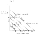
- Fig. 5 is a graph showing examples of liquid fuel heat input and gas fuel heat input according to load state in the gas turbine of Fig. 3. The above operation of the water injection device will be described with reference to Fig. 5.
- the water supply is increased from point a at no load to point e at the full load as the liquid fuel heat input is increased, that is, the water supply is increased as the oil firing load is increased, like a ⁇ b ⁇ c ⁇ d ⁇ e, and in case the load is lowered from the full load, as shown by the leftward arrow along the horizontal axis, the water supply is reduced as the load decreases, like e ⁇ d ⁇ c ⁇ b ⁇ a.
- the gas firing operation is done from no load to a certain load, for example B load, and then the operation is changed to the oil firing up to the full load, that is, the water supply is increased as the load is increased, like g ⁇ h ⁇ i, and in case the load is lowered from the full load to no load, like i ⁇ h ⁇ g, the oil fuel heat input is first reduced so that the load is lowered from the full load to B load, then the gas fuel heat input is reduced so that the load is lowered from B load to no load and the water supply is reduced corresponding to such lowering of the load, or (ii) as an alternative case, as the gas turbine is speeded after a gas ignition, the load is increased from no load to the full load by the oil and gas firing, like g ⁇ f ⁇ k and the water supply is increased corresponding to such increase of the load, and in case the load is lowered from the full load to no load, like k ⁇
- point k at the full load shows a case where the gas fuel heat input is 70% and the liquid fuel heat input is 30%, and while this ratio of the heat input may be changed freely, when the economy or the like is considered, the ratio of the gas fuel heat input to the liquid fuel heat input at the full load is usually set in the range of 70/30 to 30/70.
- Fig. 6 is a view showing an example of an injection nozzle of the combustor 1, wherein Fig. 6(a) is a partial longitudinal cross sectional view and Fig. 6(b) is a half front view.
- the injection nozzle 17 for injecting water into the combustor 1 is constructed as follows. That is, an oil hole 14 is provided in an axial central portion of the injection nozzle 17, said oil hole 14 being for injecting fuel oil, together with air swirled by a primary swirler and a secondary swirler (both not shown), into the combustor 1.
- four pieces of water holes 16 for injecting water are provided with equal pitches between each of the water holes 16 circumferentially.
- the nozzle differential pressure is as large as 40 to 50 kg/cm 2 g and the water supplied is atomized enough in operation.
- the inner pressure of the water injection manifold 2 is sufficiently higher than the inner pressure of 10 to 12 kg/cm 2 g of the turbine cylinder, hence even if a small quantity of water leaks through such small passage of the drain line, it may not necessarily be a large problem.
- the inner pressure of the water injection manifold 2 lowers rapidly and the high temperature high pressure combustion gas in the turbine cylinder may flow reversely into the water injection manifold 2 via the branch pipes 6 due to the inner pressure of 10 to 12 kg/cm 2 g of the turbine cylinder thereby to cause a eruptive breakage of the water injection manifold 2.
- the present invention provides a multifunctional water injection manifold device constructed as mentioned in the following (1) and (2):
- the water injection for lowering flame temperature in the combustor may be stopped during load operation of the gas turbine and then draining of the water injection manifold may be done immediately without waiting for the state of no load of the temperature and pressure in the combustor and turbine cylinder.
- the water injection manifold is caused to communicate with outside air by opening the air vent valve and the draining can be done naturally by the gravity of water by opening the drain valve with no need to wait for no load state. Also, even if there is a dust biting in the drain valve to lower the pressure in the water injection manifold, high temperature high pressure combustion gas in the combustor and turbine cylinder is prevented from flowing reversely toward the water injection manifold by the pressure type check valve and the eruptive damage of the water injection manifold by the combustion gas so flowing reversely can be prevented.
- the sweep operation of the water holes can be done without waiting for the draining after stop of the gas turbine.
- the sweep operation is done and the liquid fuel is prevented from trailing into the water holes opening near the oil hole, so that coking of the liquid fuel to cause a clogging of the water holes can be prevented securely.
- the water injection for NOx reduction can be stopped without damaging the gas turbine high temperature portion in any load operation of a liquid mono-fuel gas turbine or a liquid/gas dual-fuel gas turbine, thereby the operation range of the water injection in the gas turbine is broadened remarkably. Also, the high temperature portion being damaged in no case, maintenance and repair cost can be reduced and a high economical effect can be obtained.
- the draining of the manifold and the sweep operation of the water holes, which are needed usually in the gas turbine, can be done securely with no waiting time even in the case of stop of the gas turbine load operation, thereby coking of the liquid fuel does not occur in the water holes and a stable operation is realized.
- the timing of the water injection start/stop can be selected freely and a remarkable effect can be obtained in the economy, reliability and safe operation of the liquid mono-fuel gas turbine or the liquid/gas dual-fuel gas turbine.
- the present invention provides an operation method of a multifunctional water injection device comprising steps as mentioned in the following (3) to (5):
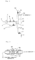
- Fig. 1 is a block diagram showing a multifunctional water injection manifold device of an embodiment according to the present invention.
- Fig. 2 is a longitudinal cross sectional view of a pressure type check valve used in the embodiment of Fig. 1.
- Fig. 3 is a view showing partially a liquid mono-fuel gas turbine or a liquid/gas dual-fuel gas turbine having a water injection manifold in the prior art, wherein an upper half part of Fig. 3 shows a cross sectional view and a lower half part of Fig. 3 shows an outside side view.
- Fig. 4 is a block diagram showing the water injection manifold in the prior art.
- Fig. 5 is a graph showing examples of liquid fuel heat input and gas fuel heat input according to load state in the gas turbine of Fig. 3.
- Fig. 6 is a view showing a fuel nozzle of a combustor in the prior art, wherein Fig. 6(a) is a partial longitudinal cross sectional view and Fig. 6(b) is a half front view.
- FIG. 1 is a block diagram showing a multifunctional water injection manifold device of the embodiment according to the present invention and Fig. 2 is a longitudinal cross sectional view of a pressure type check valve used in the embodiment of Fig. 1.
- a multifunctional water injection manifold device 50 of the present embodiment includes a water injection manifold 51, which is formed by a master pipe in an annulus of 5 to 6 m diameter surrounding a turbine cylindrical body, like the prior art water injection manifold 2 shown in Fig. 3. Between the water injection manifold 51 and the plurality of combustors 1, a plurality of branch pipes 6, each being of 15 mm diameter in the present embodiment, are provided so that each of the combustors 1 is connected to the water injection manifold 51 via the respective branch pipes 6.
- the multifunctional water injection manifold device 50 is featured in further including an air vent pipe 52 connected to a top portion of the water injection manifold 51 and an air vent valve 53 interposed in the air vent pipe 52 as well as a plurality of pressure type check valves 54, each being interposed in the respective branch pipes 6.
- the draining of the water injection manifold 51 of the present invention is carried out naturally by the gravity of water, irrespective of the state of the combustion gas in the turbine cylinder.
- the pressure in the turbine cylinder is blocked by the pressure type check valve 54, and without waiting for no load state where the temperature and pressure in the turbine cylinder are reduced, the draining can be done with both of the air vent valve 53 and the drain valve 12 being opened.
- the pressure type check valve 54 as shown in Fig. 2, comprises a valve portion 55 for opening and closing a passage passing through in the valve and a spring 56 acting on the valve portion 55 and is constructed such that liquid or gas may not flow reversely therethrough from the combustor 1 side to the water injection manifold 51 side.
- the high temperature high pressure combustion gas in the turbine cylinder may not come into the water injection manifold 51 and the draining can be done without waiting for no load state as well as there is no need of being afraid of the eruptive breakage of the water injection manifold 51 by the combustion gas flowing reversely thereinto.
- the water injection manifold 51 being a large annulus of 5 to 6 m diameter, as mentioned before, there arises a differential pressure corresponding to the water head between the top portion and the bottom portion of the water injection manifold 51, and in order to compensate this differential pressure, that is, 0.5 to 0.6 kg/cm 2 g, the spring 56 has a pressing force corresponding thereto acting on the valve portion 55.
- the injection nozzle 17 for the water injection has the oil hole 14 in the nozzle axial central portion, the water holes 16 surrounding the oil hole 14 and the gas holes 13 in the outermost circumferential portion.
- the pressure type check valve 54 is interposed in each of the branch pipes 6 for causing the water injection manifold 51 to communicate with the combustor 1, thereby the water injection manifold 51 is completely separated from the turbine cylinder side via the pressure type check valve 54 and even if dust biting occurs in the drain valve 12 to cause a small passage communicating with the outside air and the inner pressure of the water injection manifold 51 becomes lower than the pressure on the turbine cylinder side, there occurs no case where the high temperature high pressure combustion gas in the turbine cylinder may flow reversely into the water injection manifold 51.
- the pressure type check valve 54 is provided with the spring 56 having a spring force which is slightly larger than 0.5 to 0.6 kg corresponding to the water head of 5 to 6 m of the water injection manifold 51 so as to act on the valve portion 55 in the direction from the turbine cylinder side toward the water injection manifold side, thereby even when the shut-off valve 9 is closed so as to stop the water injection during any load operation of the gas turbine, the water not atomized enough by the water head of the water injection manifold 51 is prevented from flowing into the lower portion of the combustor 1 and the first stage stationary blade in the turbine cylinder.
- the high temperature portion of the gas turbine is prevented from being cooled quickly by the water not atomized enough, which results in reducing an accident of the gas turbine to obtain a high durability thereof.
- the water injection stop becomes possible at any load operation of the gas turbine without damaging the gas turbine high temperature portion, so that the gas turbine water injection operation range is broadened and the economical effect is enlarged by the reduction of the maintenance and repair cost because of no damage of the high temperature portion.
- the water holes 16 for injecting water into the combustor 1 are of a small diameter and yet are provided near the oil hole 14, hence when the oil firing gas turbine is stopped, sweep operation of the water holes 16 becomes necessary for prevention of coking, but even in this case, immediately after the draining is done, pressurized air of 5 to 7 kg/cm 2 g for sweeping is flown through the water holes 16 to overcome the spring 56 force of about 0.5 to 0.6 kgf, thereby the sweeping can be done securely.
- the draining of the manifold and the sweeping of the water injection holes as required in the ordinary gas turbine operation can be done securely so as to enable a stable operation without coking of the nozzle holes and there is obtained a remarkable effect in the economy, reliability and stable operation by the multifunctional water injection manifold device 50 of the present embodiment.
Landscapes
- Engineering & Computer Science (AREA)
- Chemical & Material Sciences (AREA)
- Combustion & Propulsion (AREA)
- Mechanical Engineering (AREA)
- General Engineering & Computer Science (AREA)
Applications Claiming Priority (2)
| Application Number | Priority Date | Filing Date | Title |
|---|---|---|---|
| JP2000066481 | 2000-03-10 | ||
| JP2000066481A JP4246874B2 (ja) | 2000-03-10 | 2000-03-10 | 多機能付加型水噴射マニホールド及びその操作方法 |
Publications (3)
| Publication Number | Publication Date |
|---|---|
| EP1132593A2 true EP1132593A2 (de) | 2001-09-12 |
| EP1132593A3 EP1132593A3 (de) | 2002-11-20 |
| EP1132593B1 EP1132593B1 (de) | 2004-08-04 |
Family
ID=18585834
Family Applications (1)
| Application Number | Title | Priority Date | Filing Date |
|---|---|---|---|
| EP00111558A Expired - Lifetime EP1132593B1 (de) | 2000-03-10 | 2000-05-30 | Mehrzweckverteilerrohr zur Wassereinspritzung einer Gasturbine und dessen Arbeitsweise |
Country Status (6)
| Country | Link |
|---|---|
| US (1) | US6349536B1 (de) |
| EP (1) | EP1132593B1 (de) |
| JP (1) | JP4246874B2 (de) |
| CN (1) | CN1233925C (de) |
| DE (1) | DE60012684T2 (de) |
| TW (1) | TW487774B (de) |
Cited By (5)
| Publication number | Priority date | Publication date | Assignee | Title |
|---|---|---|---|---|
| EP2441936A1 (de) | 2010-10-12 | 2012-04-18 | GE Energy Products France SNC | Gasturbine mit Wassereinspritzsteuerung |
| EP2613034A1 (de) * | 2012-01-09 | 2013-07-10 | Alstom Technology Ltd | Verfahren zum Betrieb einer Gasturbine |
| EP2213863A3 (de) * | 2009-01-29 | 2015-05-06 | General Electric Company | Wassereinspritzsystem für ein Gasturbinentriebwerk und entsprechendes Betriebsverfahren |
| US9958152B2 (en) | 2014-08-14 | 2018-05-01 | Siemens Aktiengesellschaft | Multi-functional fuel nozzle with an atomizer array |
| US10125991B2 (en) | 2014-08-14 | 2018-11-13 | Siemens Aktiengesellschaft | Multi-functional fuel nozzle with a heat shield |
Families Citing this family (16)
| Publication number | Priority date | Publication date | Assignee | Title |
|---|---|---|---|---|
| JP2002156115A (ja) * | 2000-11-17 | 2002-05-31 | Mitsubishi Heavy Ind Ltd | 燃焼器 |
| FR2822191B1 (fr) * | 2001-03-19 | 2003-09-19 | Inst Francais Du Petrole | Methode et dispositif pour neutraliser par injection controlee de gaz, la formation de bouchons de liquide au pied d'un riser se raccordant a une conduite d'acheminement de fluides polyphasiques |
| US7082765B2 (en) * | 2004-09-01 | 2006-08-01 | General Electric Company | Methods and apparatus for reducing gas turbine engine emissions |
| DE102004052483A1 (de) | 2004-10-28 | 2006-05-11 | Man Turbo Ag | Vorrichtung zum Einspritzen von Wasser oder Wasserdampf in das Arbeitsmittel einer Gasturbinenanlage |
| WO2007034142A1 (en) * | 2005-09-19 | 2007-03-29 | Bp Exploration Operating Company Limited | Device for controlling slugging |
| US8033115B2 (en) * | 2006-01-05 | 2011-10-11 | General Electric Company | Water injection manifold pressure relief vent |
| DE102007054502A1 (de) * | 2007-11-13 | 2009-05-14 | Häußer, Achim | Heizung mit Wassereintrag |
| CN102937050B (zh) * | 2012-10-16 | 2014-07-30 | 中国科学院工程热物理研究所 | 一种应用于车用燃气轮机燃油稳燃的高压空气路系统 |
| US9657899B2 (en) * | 2013-08-26 | 2017-05-23 | General Electric Company | Replacement oil cartridge tip and method |
| JP6086860B2 (ja) * | 2013-11-29 | 2017-03-01 | 三菱日立パワーシステムズ株式会社 | ノズル、燃焼器、及びガスタービン |
| JP2016048044A (ja) * | 2014-08-27 | 2016-04-07 | 川崎重工業株式会社 | ガスタービンエンジンシステム |
| CN104454174A (zh) * | 2014-10-13 | 2015-03-25 | 罗显平 | 一种提高燃气发动机动力输出功率的方法 |
| US10215060B2 (en) * | 2014-11-06 | 2019-02-26 | Powerphase Llc | Gas turbine efficiency and power augmentation improvements utilizing heated compressed air |
| FR3030628B1 (fr) * | 2014-12-23 | 2017-02-03 | Ge Energy Products France Snc | Installation et procede d'alimentation d'une chambre de combustion, notamment d'une turbine a gaz, a injection d'eau dans une cavite d'un circuit de purge |
| US10082083B2 (en) * | 2015-12-22 | 2018-09-25 | General Electric Company | False start drain system with vertical header |
| USD1050185S1 (en) * | 2022-08-24 | 2024-11-05 | Thomas Eugene Nelson | Injection manifold |
Family Cites Families (7)
| Publication number | Priority date | Publication date | Assignee | Title |
|---|---|---|---|---|
| US2633860A (en) * | 1947-04-04 | 1953-04-07 | Lockheed Aircraft Corp | Sequential and differential valve actuation |
| US3805519A (en) * | 1972-05-05 | 1974-04-23 | Westinghouse Electric Corp | Fuel control system for a multi-fuel gas turbine |
| US3826080A (en) * | 1973-03-15 | 1974-07-30 | Westinghouse Electric Corp | System for reducing nitrogen-oxygen compound in the exhaust of a gas turbine |
| US4893467A (en) * | 1988-07-13 | 1990-01-16 | Gas Research Institute | Control system for use with steam injected gas turbine |
| US5175994A (en) * | 1991-05-03 | 1993-01-05 | United Technologies Corporation | Combustion section supply system having fuel and water injection for a rotary machine |
| US5784875A (en) * | 1995-11-27 | 1998-07-28 | Innovative Control Systems, Inc. | Water injection into a gas turbine using purge air |
| US6145294A (en) * | 1998-04-09 | 2000-11-14 | General Electric Co. | Liquid fuel and water injection purge system for a gas turbine |
-
2000
- 2000-03-10 JP JP2000066481A patent/JP4246874B2/ja not_active Expired - Fee Related
- 2000-04-05 TW TW089106216A patent/TW487774B/zh not_active IP Right Cessation
- 2000-05-30 EP EP00111558A patent/EP1132593B1/de not_active Expired - Lifetime
- 2000-05-30 DE DE60012684T patent/DE60012684T2/de not_active Expired - Lifetime
- 2000-06-12 US US09/592,281 patent/US6349536B1/en not_active Expired - Lifetime
- 2000-07-26 CN CNB001219340A patent/CN1233925C/zh not_active Expired - Fee Related
Cited By (6)
| Publication number | Priority date | Publication date | Assignee | Title |
|---|---|---|---|---|
| EP2213863A3 (de) * | 2009-01-29 | 2015-05-06 | General Electric Company | Wassereinspritzsystem für ein Gasturbinentriebwerk und entsprechendes Betriebsverfahren |
| EP2441936A1 (de) | 2010-10-12 | 2012-04-18 | GE Energy Products France SNC | Gasturbine mit Wassereinspritzsteuerung |
| EP2613034A1 (de) * | 2012-01-09 | 2013-07-10 | Alstom Technology Ltd | Verfahren zum Betrieb einer Gasturbine |
| CH705965A1 (de) * | 2012-01-09 | 2013-07-15 | Alstom Technology Ltd | Verfahren zum Betrieb einer Gasturbine. |
| US9958152B2 (en) | 2014-08-14 | 2018-05-01 | Siemens Aktiengesellschaft | Multi-functional fuel nozzle with an atomizer array |
| US10125991B2 (en) | 2014-08-14 | 2018-11-13 | Siemens Aktiengesellschaft | Multi-functional fuel nozzle with a heat shield |
Also Published As
| Publication number | Publication date |
|---|---|
| TW487774B (en) | 2002-05-21 |
| EP1132593B1 (de) | 2004-08-04 |
| US6349536B1 (en) | 2002-02-26 |
| CN1313460A (zh) | 2001-09-19 |
| EP1132593A3 (de) | 2002-11-20 |
| DE60012684T2 (de) | 2005-07-28 |
| JP2001254631A (ja) | 2001-09-21 |
| JP4246874B2 (ja) | 2009-04-02 |
| CN1233925C (zh) | 2005-12-28 |
| DE60012684D1 (de) | 2004-09-09 |
Similar Documents
| Publication | Publication Date | Title |
|---|---|---|
| EP1132593B1 (de) | Mehrzweckverteilerrohr zur Wassereinspritzung einer Gasturbine und dessen Arbeitsweise | |
| EP1503142B1 (de) | Verfahren zum Betrieb eines Kombikraftwerks mit einer Kohlevergasungsanlage | |
| EP0724115B1 (de) | Reinigungsverfahren für Gasturbinen-Einspritzdüse | |
| US6598383B1 (en) | Fuel system configuration and method for staging fuel for gas turbines utilizing both gaseous and liquid fuels | |
| CA2291374C (en) | A dual fuel nozzle | |
| US6826913B2 (en) | Airflow modulation technique for low emissions combustors | |
| CN1769655B (zh) | 燃气轮机发电设备 | |
| EP1199454A2 (de) | Steuersystem für das Brennstoffverteilungssystem einer Gasturbine | |
| EP0952317A2 (de) | Spülsystem für die Kraftstoffzufuhr einer Gasturbine | |
| JPH1019258A (ja) | ガスタービン燃焼器用の拡散・予混合ノズル | |
| KR20230046988A (ko) | 가스 터빈 설비 | |
| US5309710A (en) | Gas turbine combustor having poppet valves for air distribution control | |
| JP4659543B2 (ja) | ガスタービン燃焼器、その燃料のカーボン化防止方法及びパージ方法 | |
| EP0866274B1 (de) | Doppelkonisches Überschlagrohr | |
| EP3394513B1 (de) | Gestuftes dampfeinspritzsystem | |
| JPS60164627A (ja) | 燃料ノズルパ−ジシステム装置 | |
| EP0646706B1 (de) | Brennstoffeinspritzsystem mit selbstunterhaltender Reinigung | |
| SU1620580A1 (ru) | Способ запуска огнеструйной горелки и устройство дл его осуществлени | |
| CA3195199A1 (en) | Staged gas injection system | |
| JPS61128023A (ja) | バ−ナ装置の残油燃焼方法 | |
| JPH04124522A (ja) | 燃焼装置の燃料供給方法、燃料供給系統および拡散燃料ノズル | |
| JP2006300419A (ja) | 燃焼制御方法および燃焼装置 |
Legal Events
| Date | Code | Title | Description |
|---|---|---|---|
| PUAI | Public reference made under article 153(3) epc to a published international application that has entered the european phase |
Free format text: ORIGINAL CODE: 0009012 |
|
| 17P | Request for examination filed |
Effective date: 20000627 |
|
| AK | Designated contracting states |
Kind code of ref document: A2 Designated state(s): AT BE CH CY DE DK ES FI FR GB GR IE IT LI LU MC NL PT SE |
|
| AX | Request for extension of the european patent |
Free format text: AL;LT;LV;MK;RO;SI |
|
| PUAL | Search report despatched |
Free format text: ORIGINAL CODE: 0009013 |
|
| AK | Designated contracting states |
Kind code of ref document: A3 Designated state(s): AT BE CH CY DE DK ES FI FR GB GR IE IT LI LU MC NL PT SE |
|
| AX | Request for extension of the european patent |
Free format text: AL;LT;LV;MK;RO;SI |
|
| RIC1 | Information provided on ipc code assigned before grant |
Free format text: 7F 02C 3/30 A, 7F 02C 7/232 B, 7F 23L 7/00 B, 7F 02C 7/22 B |
|
| AKX | Designation fees paid |
Designated state(s): CH DE LI |
|
| 17Q | First examination report despatched |
Effective date: 20030703 |
|
| RTI1 | Title (correction) |
Free format text: GAS TURBINE INCLUDING MULTIFUNCTIONAL WATER INJECTION MANIFOLD AND OPERATION METHOD THEREOF |
|
| GRAP | Despatch of communication of intention to grant a patent |
Free format text: ORIGINAL CODE: EPIDOSNIGR1 |
|
| GRAS | Grant fee paid |
Free format text: ORIGINAL CODE: EPIDOSNIGR3 |
|
| GRAA | (expected) grant |
Free format text: ORIGINAL CODE: 0009210 |
|
| AK | Designated contracting states |
Kind code of ref document: B1 Designated state(s): CH DE LI |
|
| PG25 | Lapsed in a contracting state [announced via postgrant information from national office to epo] |
Ref country code: LI Free format text: LAPSE BECAUSE OF FAILURE TO SUBMIT A TRANSLATION OF THE DESCRIPTION OR TO PAY THE FEE WITHIN THE PRESCRIBED TIME-LIMIT Effective date: 20040804 Ref country code: CH Free format text: LAPSE BECAUSE OF FAILURE TO SUBMIT A TRANSLATION OF THE DESCRIPTION OR TO PAY THE FEE WITHIN THE PRESCRIBED TIME-LIMIT Effective date: 20040804 |
|
| REG | Reference to a national code |
Ref country code: CH Ref legal event code: EP |
|
| REG | Reference to a national code |
Ref country code: IE Ref legal event code: FG4D |
|
| REF | Corresponds to: |
Ref document number: 60012684 Country of ref document: DE Date of ref document: 20040909 Kind code of ref document: P |
|
| REG | Reference to a national code |
Ref country code: CH Ref legal event code: PL |
|
| PLBE | No opposition filed within time limit |
Free format text: ORIGINAL CODE: 0009261 |
|
| STAA | Information on the status of an ep patent application or granted ep patent |
Free format text: STATUS: NO OPPOSITION FILED WITHIN TIME LIMIT |
|
| 26N | No opposition filed |
Effective date: 20050506 |
|
| REG | Reference to a national code |
Ref country code: DE Ref legal event code: R082 Ref document number: 60012684 Country of ref document: DE Representative=s name: PATENTANWAELTE HENKEL, BREUER & PARTNER, DE Ref country code: DE Ref legal event code: R081 Ref document number: 60012684 Country of ref document: DE Owner name: MITSUBISHI HITACHI POWER SYSTEMS, LTD., YOKOHA, JP Free format text: FORMER OWNER: MITSUBISHI HEAVY INDUSTRIES, LTD., TOKYO, JP Ref country code: DE Ref legal event code: R082 Ref document number: 60012684 Country of ref document: DE Representative=s name: PATENTANWAELTE HENKEL, BREUER & PARTNER MBB, DE |
|
| REG | Reference to a national code |
Ref country code: DE Ref legal event code: R082 Ref document number: 60012684 Country of ref document: DE Representative=s name: PATENTANWAELTE HENKEL, BREUER & PARTNER, DE Effective date: 20150601 Ref country code: DE Ref legal event code: R081 Ref document number: 60012684 Country of ref document: DE Owner name: MITSUBISHI HITACHI POWER SYSTEMS, LTD., YOKOHA, JP Free format text: FORMER OWNER: MITSUBISHI HEAVY INDUSTRIES, LTD., TOKYO, JP Effective date: 20150601 |
|
| PGFP | Annual fee paid to national office [announced via postgrant information from national office to epo] |
Ref country code: DE Payment date: 20170523 Year of fee payment: 18 |
|
| REG | Reference to a national code |
Ref country code: DE Ref legal event code: R119 Ref document number: 60012684 Country of ref document: DE |
|
| PG25 | Lapsed in a contracting state [announced via postgrant information from national office to epo] |
Ref country code: DE Free format text: LAPSE BECAUSE OF NON-PAYMENT OF DUE FEES Effective date: 20181201 |