EP1132604B1 - Verfahren zum Überwachen der Kraftstoffeinspritzung bei einer Brennkraftmaschine - Google Patents
Verfahren zum Überwachen der Kraftstoffeinspritzung bei einer Brennkraftmaschine Download PDFInfo
- Publication number
- EP1132604B1 EP1132604B1 EP01104949A EP01104949A EP1132604B1 EP 1132604 B1 EP1132604 B1 EP 1132604B1 EP 01104949 A EP01104949 A EP 01104949A EP 01104949 A EP01104949 A EP 01104949A EP 1132604 B1 EP1132604 B1 EP 1132604B1
- Authority
- EP
- European Patent Office
- Prior art keywords
- combustion engine
- fuel
- internal combustion
- injected
- max
- Prior art date
- Legal status (The legal status is an assumption and is not a legal conclusion. Google has not performed a legal analysis and makes no representation as to the accuracy of the status listed.)
- Expired - Lifetime
Links
- 239000000446 fuel Substances 0.000 title claims description 48
- 238000002485 combustion reaction Methods 0.000 title claims description 31
- 238000000034 method Methods 0.000 title claims description 26
- 238000002347 injection Methods 0.000 title claims description 20
- 239000007924 injection Substances 0.000 title claims description 20
- 238000012544 monitoring process Methods 0.000 title claims description 11
- 230000001105 regulatory effect Effects 0.000 claims description 6
- 239000002826 coolant Substances 0.000 claims description 4
- 230000006870 function Effects 0.000 claims description 2
- 238000010586 diagram Methods 0.000 description 7
- 238000012806 monitoring device Methods 0.000 description 4
- 230000007257 malfunction Effects 0.000 description 3
- 238000012360 testing method Methods 0.000 description 3
- 230000032683 aging Effects 0.000 description 2
- 238000004378 air conditioning Methods 0.000 description 2
- 230000008859 change Effects 0.000 description 2
- 230000004913 activation Effects 0.000 description 1
- 230000006978 adaptation Effects 0.000 description 1
- 230000008901 benefit Effects 0.000 description 1
- 239000003054 catalyst Substances 0.000 description 1
- 230000001276 controlling effect Effects 0.000 description 1
- 230000007547 defect Effects 0.000 description 1
- 230000001419 dependent effect Effects 0.000 description 1
- 238000001514 detection method Methods 0.000 description 1
- 238000003745 diagnosis Methods 0.000 description 1
- 238000002405 diagnostic procedure Methods 0.000 description 1
- 230000007613 environmental effect Effects 0.000 description 1
- 239000003344 environmental pollutant Substances 0.000 description 1
- 239000002245 particle Substances 0.000 description 1
- 231100000719 pollutant Toxicity 0.000 description 1
- 238000010972 statistical evaluation Methods 0.000 description 1
- 238000012549 training Methods 0.000 description 1
Images


Classifications
-
- F—MECHANICAL ENGINEERING; LIGHTING; HEATING; WEAPONS; BLASTING
- F02—COMBUSTION ENGINES; HOT-GAS OR COMBUSTION-PRODUCT ENGINE PLANTS
- F02D—CONTROLLING COMBUSTION ENGINES
- F02D41/00—Electrical control of supply of combustible mixture or its constituents
- F02D41/22—Safety or indicating devices for abnormal conditions
- F02D41/221—Safety or indicating devices for abnormal conditions relating to the failure of actuators or electrically driven elements
-
- F—MECHANICAL ENGINEERING; LIGHTING; HEATING; WEAPONS; BLASTING
- F02—COMBUSTION ENGINES; HOT-GAS OR COMBUSTION-PRODUCT ENGINE PLANTS
- F02D—CONTROLLING COMBUSTION ENGINES
- F02D2200/00—Input parameters for engine control
- F02D2200/50—Input parameters for engine control said parameters being related to the vehicle or its components
- F02D2200/501—Vehicle speed
Definitions
- the invention relates to a method for monitoring the Fuel injection in an internal combustion engine, in particular in a diesel internal combustion engine, the speed-controlled Area is operated.
- Such on-board diagnostic systems are according to the directive 98/69 / EG of the European Parliament and of the Council in the future also required for diesel vehicles.
- the task here next to the monitoring of the efficiency is a possible existing catalyst, a particle filter and one electronic fuel quantity control of the fuel injection system also the monitoring of those connected to a computer emission-relevant components or subsystems of the Powertrain whose failure or malfunction lead to it could that the exhaust emissions meet the predetermined limits exceed. Monitoring the actually injected The amount of fuel is a key requirement.
- DE 41 03 840 A1 describes an error monitoring method for finding errors in control loops, in particular in control loops for fuel metering in internal combustion engines known, with at least one control loop size being exceeded a specifiable limit is monitored and as Control loop variable monitors the manipulated variable of the control loop becomes.
- the manipulated variable is exceeded of a manipulated variable maximum value and falling below one Control value minimum value monitored.
- the minimum error time is a limit is an error longer than the minimum error time within of a test interval, the error time is longer or equal to the minimum error time, an error message is issued. In the event of an error message, the fuel supply interrupted to the internal combustion engine.
- the invention is therefore based on the object of a method specify with which the injected in a simple manner Fuel quantity can be monitored.
- the amount of fuel to be injected is determined solely by the Speed of the internal combustion engine regulated. If there are no errors Vehicle operation and defined operating parameters moved the amount of fuel regulated in this way between applicable upper and lower limits. These limits are set so that they are exceeded or undershot diagnosed as faulty injection can be, which is an exceedance by the legislature may result in predetermined exhaust gas limit values. It will therefore checks whether the amount of fuel is within the range of an upper and lower limit of a certain range.
- the speed-controlled idle operation of the internal combustion engine when the vehicle is at a standstill represents an easily reproducible operating state which is in the European test cycle a significant percentage according to the above-mentioned guideline Share (city driving cycle: 30%).
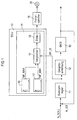
- FIG (BKM) 10 A diesel internal combustion engine is very simplified in FIG (BKM) 10 with a diesel control device assigned to it shown, with only those parts shown are necessary for understanding the invention. Particular attention is paid to the representation of the exhaust gas aftertreatment system and the fuel circuit have been dispensed with.
- the diesel control device has a speed controller 11, which is the difference between a predetermined target speed N_SOLL and that detected by means of a sensor, not shown Actual speed N_IST is supplied to internal combustion engine 10 becomes.
- the speed controller 11 acts on an injection device 12 a, for example as an injection pump or as Storage injection system (Common Rail System) be formed can.
- the closed control loop creates a certain one Amount of fuel, for example at idle Internal combustion engine 10, the fuel quantity MF_IS, which means the injection device 12 of the internal combustion engine 10 is fed.
- One used to monitor the amount of fuel injected Monitoring device 14 has a comparator 15 on, the amount of fuel output by the speed controller 11 MF_IS in mg / stroke with two predefined threshold values for compares the fuel quantities MF_MAX and MF_MIN.
- This Threshold values MF_MAX and MF_MIN are dependent on the specified emission limit values are applied and are in one Memory stored. You can, for example, depending on the Temperature of the coolant of the internal combustion engine 10 as Characteristic curves are stored in maps 16, 17.
- the comparator 14 is connected to an input port of a counter 18, whose output port is connected to a fault memory 19 is.
- a fault warning lamp 20 is assigned to the fault memory 19.
- the function of the monitoring device 14 is based on the description of Figures 2-5 explained in more detail.
- the speed controller 11 is for the sake of Clarity drawn as a separate component, he can but also in the same way as the monitoring device 14 controlling and regulating the operation of the internal combustion engine 10 Control device (ECU) 13 may be integrated.
- ECU Control device
- the speed controller varies to adjust the idle speed 11 the fuel injection quantity until the measured Actual speed is equal to the specified target speed.
- the the idling speed that occurs serves to compensate for the Sum of the external load torques and all torque losses on the internal combustion engine itself, e.g. of compensation internal friction torques.
- the causes of faulty fuel injections can be e.g. in the event of defects in the injection nozzles, in the electrical Control of the same or faulty signals from a Pressure sensor are located, which detects the pressure in the fuel circuit.
- a Pressure sensor which detects the pressure in the fuel circuit.
- the thresholds MF_MAX and MF_MIN for monitoring the injected The amount of fuel is then adjusted in a suitable manner. This can be done either by tracking the thresholds (Offset compensation) are done as it is in the diagram is shown by Figure 4, or by expanding the through the limited band thresholds are reached.
- the Unit for the time axis t is a multiple of the unit of Time axes t in the illustration according to FIGS. 2-4. That is why the course of the injected fuel quantity MF_IS within the threshold values compared to the other courses significantly smoother.
- the method is shown in FIG. 5 in the form of a flow chart shown to monitor the amount of fuel injected.
- predetermined Limit values e.g. 1.8 km / h
- the query in step S1 is negative, it branches to the beginning of the procedure, otherwise is queried in a method step S2 whether predetermined ones Operating conditions are met. This can in particular be checked whether the temperature of the coolant of the Internal combustion engine 10 exceeds a predetermined threshold and has no disturbing external load moments for example by switching on the air conditioning, occur. This query serves to reproducible states for checking the amount of fuel injected
- step S3 the current value for the injected fuel quantity MF_IS read in and checked in a method step S4, whether this value MF_IS within the by the threshold values MF_MAX and MF_MIN limited area. Is this the If this is the case, the injector operates correctly closed and branched to the beginning of the procedure. Is the value for the amount of fuel injected MF_IS outside the specified area, is in the procedural step S5 increments the counter reading of the counter 18 (FIG. 1). Then in a method step S6 checks whether a predetermined end value for the counter reading is reached.
Landscapes
- Engineering & Computer Science (AREA)
- Chemical & Material Sciences (AREA)
- Combustion & Propulsion (AREA)
- Mechanical Engineering (AREA)
- General Engineering & Computer Science (AREA)
- Electrical Control Of Air Or Fuel Supplied To Internal-Combustion Engine (AREA)
- Combined Controls Of Internal Combustion Engines (AREA)
Description
- Figur 1
- ein Blockschaltbild einer Dieselbrennkraftmaschine mit einer Überwachungseinrichtung für die eingespritzte Kraftstoffmenge,
- Figur 2
- ein Diagramm, das den zeitlichen Verlauf der eingespritzten Kraftstoffmenge bei fehlerfreiem Betrieb der Brennkraftmaschine zeigt,
- Figur 3
- ein Diagramm, das den zeitlichen Verlauf der eingespritzten Kraftstoffmenge bei fehlerhaftem Betrieb der Brennkraftmaschine zeigt,
- Figur 4
- ein Diagramm, das die allmähliche Veränderung der Kraftstoffeinspritzmenge aufgrund von Systemalterung zeigt und
- Figur 5
- ein Ablaufdiagramm zum Überwachen der eingespritzten Kraftstoffmenge
Claims (9)
- Verfahren zum Überwachen der Kraftstoffeinspritzung bei einer Brennkraftmaschine (10), wobeiin drehzahlgeregelten Betriebszuständen der Brennkraftmaschine (10) die einzuspritzende Kraftstoffmenge (MF_IS) über die Drehzahl (N_IST) der Brennkraftmaschine (10) geregelt wird,die einzuspritzende Kraftstoffmenge (MF_IS) erfasst und mit vorgegebenen Schwellenwerten (MF_MAX, MF_MIN) verglichen wird,auf eine fehlerhafte Einspritzung geschlossen wird, wenn die eingespritzte Kraftstoffmenge (MF_IS) außerhalb eines durch die Schwellenwerte (MF_MAX, MF_MIN) begrenzten Bereiches liegt, dadurch gekennzeichnet, dass der drehzahlgeregelte Betriebszustand der Brennkraftmaschine der Leerlauf ist.
- Verfahren nach Anspruch 1, dadurch gekennzeichnet, dass die Überprüfung bei einer Fahrzeuggeschwindigkeit (V) erfolgt, die kleiner als ein vorgegebener Wert ist.
- Verfahren nach Anspruch 2, dadurch gekennzeichnet, dass der vorgegebene Wert Null ist.
- Verfahren nach einem der vorhergehenden Ansprüche, dadurch gekennzeichnet, dass auf eine fehlerhafte Einspritzung geschlossen wird, wenn eine vorgegebene Anzahl von außerhalb des Bereiches liegenden Werte für die einzuspritzende Kraftstoffmenge erreicht ist.
- Verfahren nach Anspruch 1 oder 4, dadurch gekennzeichnet, dass bei Auftreten einer fehlerhaften Einspritzung ein Eintrag in einen Fehlerspeicher (19) erfolgt.
- Verfahren nach Anspruch 5, dadurch gekennzeichnet, dass bei Auftreten einer fehlerhaften Einspritzung eine Fehlerwarnlampe (20) aktiviert wird.
- Verfahren nach Anspruch 1, dadurch gekennzeichnet, dass die Schwellenwerte (MF_MAX, MF_MIN) unter Berücksichtigung von vorgegebenen Emisssionsgrenzwerten appliziert werden und in einem Speicher abgelegt sind.
- Verfahren nach Anspruch 7, dadurch gekennzeichnet, dass die Schwellenwerte (MF_MAX, MF_MIN) zusätzlich von der Temperatur des Kühlmittels der Brennkraftmaschine (10) abhängig in Kennfelder (16,17) abgelegt sind.
- Verfahren nach Anspruch 7 oder 8, dadurch gekennzeichnet, dass die Schwellenwerte (MF_MAX, MF_MIN) nach Erreichen einer vorgegebenen Mindestfahrleistung des mittels der Brennkraftmaschine (19) angetriebenen Fahrzeuges angepasst werden, um die Veränderungen der einzuspritzenden Kraftstoffmenge (MF_IS) zu berücksichtigen.
Applications Claiming Priority (2)
| Application Number | Priority Date | Filing Date | Title |
|---|---|---|---|
| DE10010847 | 2000-03-06 | ||
| DE10010847A DE10010847C1 (de) | 2000-03-06 | 2000-03-06 | Verfahren zum Überwachen der Kraftstoffeinspritzung bei einer Brennkraftmaschine |
Publications (3)
| Publication Number | Publication Date |
|---|---|
| EP1132604A2 EP1132604A2 (de) | 2001-09-12 |
| EP1132604A3 EP1132604A3 (de) | 2003-03-19 |
| EP1132604B1 true EP1132604B1 (de) | 2004-08-18 |
Family
ID=7633680
Family Applications (1)
| Application Number | Title | Priority Date | Filing Date |
|---|---|---|---|
| EP01104949A Expired - Lifetime EP1132604B1 (de) | 2000-03-06 | 2001-02-28 | Verfahren zum Überwachen der Kraftstoffeinspritzung bei einer Brennkraftmaschine |
Country Status (2)
| Country | Link |
|---|---|
| EP (1) | EP1132604B1 (de) |
| DE (2) | DE10010847C1 (de) |
Families Citing this family (5)
| Publication number | Priority date | Publication date | Assignee | Title |
|---|---|---|---|---|
| JP4306123B2 (ja) * | 2000-12-15 | 2009-07-29 | トヨタ自動車株式会社 | 内燃機関の燃料供給系異常検出装置 |
| EP1403750A1 (de) * | 2002-09-27 | 2004-03-31 | Peter Renner | System zum Aufspüren und Bewerten von Veränderungen an technischen Prozessen |
| DE102007049711A1 (de) * | 2007-10-17 | 2009-04-23 | Robert Bosch Gmbh | Verfahren zum Betreiben eines Steuergeräts |
| JP2009275653A (ja) * | 2008-05-16 | 2009-11-26 | Honda Motor Co Ltd | アイドル制御系の異常判定装置 |
| DE102016219479A1 (de) * | 2016-10-07 | 2018-04-12 | Robert Bosch Gmbh | Verfahren und Vorrichtung zum Ermitteln eines Schädigungszustands einer Komponente eines Fahrzeugs |
Family Cites Families (6)
| Publication number | Priority date | Publication date | Assignee | Title |
|---|---|---|---|---|
| DE4103840B4 (de) * | 1991-02-08 | 2011-02-10 | Robert Bosch Gmbh | Fehler-Überwachungsverfahren |
| US5535621A (en) * | 1994-03-02 | 1996-07-16 | Ford Motor Company | On-board detection of fuel injector malfunction |
| DE19620038B4 (de) * | 1996-05-17 | 2007-08-23 | Robert Bosch Gmbh | Verfahren und Vorrichtung zur Überwachung eines Kraftstoffzumeßsystems |
| DE19626690B4 (de) * | 1996-07-03 | 2008-12-11 | Robert Bosch Gmbh | Verfahren und Vorrichtung zur Überwachung eines Kraftstoffzumeßsystems einer Brennkraftmaschine |
| DE19637395C1 (de) * | 1996-09-13 | 1998-04-16 | Siemens Ag | Verfahren und Einrichtung zur Steuerung der einer Brennkraftmaschine zuzuführenden Kraftstoffmenge |
| GB2323687B (en) * | 1997-03-25 | 1999-03-10 | Nissan Motor | Diesel engine fuel injection device |
-
2000
- 2000-03-06 DE DE10010847A patent/DE10010847C1/de not_active Expired - Fee Related
-
2001
- 2001-02-28 DE DE50103278T patent/DE50103278D1/de not_active Expired - Lifetime
- 2001-02-28 EP EP01104949A patent/EP1132604B1/de not_active Expired - Lifetime
Also Published As
| Publication number | Publication date |
|---|---|
| EP1132604A3 (de) | 2003-03-19 |
| DE10010847C1 (de) | 2001-09-20 |
| DE50103278D1 (de) | 2004-09-23 |
| EP1132604A2 (de) | 2001-09-12 |
Similar Documents
| Publication | Publication Date | Title |
|---|---|---|
| EP1745197B1 (de) | Verfahren zum einbringen eines reagenzmittels in einen abgaskanal einer brennkraftmaschine | |
| EP1373693B2 (de) | Verfahren und vorrichtung zur überwachung eines abgasnachbehandlungssystems | |
| EP1305514B1 (de) | Verfahren zur diagnose der funktionstüchtigkeit eines abgasrückführungssystems einer brennkraftmaschine | |
| EP1192340B1 (de) | Verfahren zum überprüfen eines dreiwege-abgaskatalysators einer brennkraftmaschine | |
| DE4426494A1 (de) | Einrichtung zur Überwachung des Kühlsystems bei einer Brennkraftmaschine | |
| DE102013226796A1 (de) | Verfahren zum Überprüfen eines Temperatursensors in einem SCR-Abgasnachbehandlungssystem | |
| EP1121519A1 (de) | Verfahren und vorrichtung zur de-sulfatierung eines nox-speicherkatalysators | |
| WO2008080670A1 (de) | Verfahren und vorrichtung zur ermittlung einer optimierten notlauffunktion bei einem mit einem fehler behafteten motor eines kraftfahrzeugs | |
| DE19836845B4 (de) | Verfahren und Vorrichtung zur Steuerung einer Antriebseinheit eines Kraftfahrzeugs | |
| EP1305513B1 (de) | Verfahren zum überprüfen der funktionstüchtigkeit eines abgasrückführungssystems einer brennkraftmaschine | |
| DE4302483C2 (de) | Verfahren und Vorrichtung zur Steuerung einer Brennkraftmaschine | |
| DE102013201997A1 (de) | Verfahren und Vorrichtung zum Betrieb einer Kraftstoffeinspritzeinrichtung insbesondere eines Kraftfahrzeuges | |
| DE19928477A1 (de) | Verfahren und Vorrichtung zur Steuerung einer Antriebseinheit eines Fahrzeugs | |
| DE19620038B4 (de) | Verfahren und Vorrichtung zur Überwachung eines Kraftstoffzumeßsystems | |
| DE102007003547A1 (de) | Verfahren zur Diagnose eines eine Abgasbehandlungsvorrichtung enthaltenden Abgasbereichs einer Brennkraftmaschine und Vorrichtung zur Durchführung des Verfahrens | |
| DE10010847C1 (de) | Verfahren zum Überwachen der Kraftstoffeinspritzung bei einer Brennkraftmaschine | |
| EP1180210B2 (de) | Verfahren und vorrichtung zur steuerung einer brennkraftmaschine mit einem abgasnachbehandlungssystem | |
| DE10021086B4 (de) | Verfahren zum Bestimmen des Kraftstoffmassenstroms bei einer Brennkraftmaschine | |
| DE4210647A1 (de) | Anormalitaetserfassungseinrichtung fuer einen kraftfahrzeugmotor | |
| DE112014001033B4 (de) | Überwachungseinheit und Verfahren zur Überwachung eines Kraftstoffsystems | |
| DE19641942B4 (de) | Verfahren und Vorrichtung zur Fehlererkennung bei einer Brennkraftmaschine | |
| DE102019008535A1 (de) | Verfahren zum Betreiben eines Kraftfahrzeugs, insbesondere eines Kraftwagens | |
| DE19707868B4 (de) | Verfahren und Vorrichtung zur Überwachung eines Systems zur Steuerung einer Brennkraftmaschine | |
| EP0828069A2 (de) | Verfahren und Vorrichtung zur Überwachung eines Durchflussbegrenzers eines Kraftstoffzumesssystems einer Brennkraftmaschine | |
| DE102016220029A1 (de) | Verfahren und Vorrichtung zur Überwachung eines Luftmassensensors einer Brennkraftmaschine mit Abgasrückführung |
Legal Events
| Date | Code | Title | Description |
|---|---|---|---|
| PUAI | Public reference made under article 153(3) epc to a published international application that has entered the european phase |
Free format text: ORIGINAL CODE: 0009012 |
|
| AK | Designated contracting states |
Kind code of ref document: A2 Designated state(s): AT BE CH CY DE DK ES FI FR GB GR IE IT LI LU MC NL PT SE TR |
|
| AX | Request for extension of the european patent |
Free format text: AL;LT;LV;MK;RO;SI |
|
| PUAL | Search report despatched |
Free format text: ORIGINAL CODE: 0009013 |
|
| AK | Designated contracting states |
Kind code of ref document: A3 Designated state(s): AT BE CH CY DE DK ES FI FR GB GR IE IT LI LU MC NL PT SE TR |
|
| AX | Request for extension of the european patent |
Extension state: AL LT LV MK RO SI |
|
| 17P | Request for examination filed |
Effective date: 20030417 |
|
| 17Q | First examination report despatched |
Effective date: 20030821 |
|
| AKX | Designation fees paid |
Designated state(s): DE FR IT |
|
| GRAP | Despatch of communication of intention to grant a patent |
Free format text: ORIGINAL CODE: EPIDOSNIGR1 |
|
| GRAA | (expected) grant |
Free format text: ORIGINAL CODE: 0009210 |
|
| GRAS | Grant fee paid |
Free format text: ORIGINAL CODE: EPIDOSNIGR3 |
|
| AK | Designated contracting states |
Kind code of ref document: B1 Designated state(s): DE FR IT |
|
| REG | Reference to a national code |
Ref country code: IE Ref legal event code: FG4D Free format text: GERMAN |
|
| REF | Corresponds to: |
Ref document number: 50103278 Country of ref document: DE Date of ref document: 20040923 Kind code of ref document: P |
|
| REG | Reference to a national code |
Ref country code: IE Ref legal event code: FD4D |
|
| ET | Fr: translation filed | ||
| PLBE | No opposition filed within time limit |
Free format text: ORIGINAL CODE: 0009261 |
|
| STAA | Information on the status of an ep patent application or granted ep patent |
Free format text: STATUS: NO OPPOSITION FILED WITHIN TIME LIMIT |
|
| 26N | No opposition filed |
Effective date: 20050519 |
|
| REG | Reference to a national code |
Ref country code: FR Ref legal event code: TP |
|
| PGFP | Annual fee paid to national office [announced via postgrant information from national office to epo] |
Ref country code: FR Payment date: 20120227 Year of fee payment: 12 |
|
| PGFP | Annual fee paid to national office [announced via postgrant information from national office to epo] |
Ref country code: IT Payment date: 20120223 Year of fee payment: 12 |
|
| REG | Reference to a national code |
Ref country code: FR Ref legal event code: ST Effective date: 20131031 |
|
| PG25 | Lapsed in a contracting state [announced via postgrant information from national office to epo] |
Ref country code: IT Free format text: LAPSE BECAUSE OF NON-PAYMENT OF DUE FEES Effective date: 20130228 |
|
| PG25 | Lapsed in a contracting state [announced via postgrant information from national office to epo] |
Ref country code: FR Free format text: LAPSE BECAUSE OF NON-PAYMENT OF DUE FEES Effective date: 20130228 |
|
| PGFP | Annual fee paid to national office [announced via postgrant information from national office to epo] |
Ref country code: DE Payment date: 20180228 Year of fee payment: 18 |
|
| REG | Reference to a national code |
Ref country code: DE Ref legal event code: R119 Ref document number: 50103278 Country of ref document: DE |
|
| PG25 | Lapsed in a contracting state [announced via postgrant information from national office to epo] |
Ref country code: DE Free format text: LAPSE BECAUSE OF NON-PAYMENT OF DUE FEES Effective date: 20190903 |