EP1132609B1 - Echangeur de chaleur disposé dans un dispositif de recirculation de gaz d'échappement - Google Patents
Echangeur de chaleur disposé dans un dispositif de recirculation de gaz d'échappement Download PDFInfo
- Publication number
- EP1132609B1 EP1132609B1 EP01103422A EP01103422A EP1132609B1 EP 1132609 B1 EP1132609 B1 EP 1132609B1 EP 01103422 A EP01103422 A EP 01103422A EP 01103422 A EP01103422 A EP 01103422A EP 1132609 B1 EP1132609 B1 EP 1132609B1
- Authority
- EP
- European Patent Office
- Prior art keywords
- exhaust
- heat exchanger
- exhaust heat
- exhaust gas
- manifold
- Prior art date
- Legal status (The legal status is an assumption and is not a legal conclusion. Google has not performed a legal analysis and makes no representation as to the accuracy of the status listed.)
- Expired - Lifetime
Links
Images


Classifications
-
- F—MECHANICAL ENGINEERING; LIGHTING; HEATING; WEAPONS; BLASTING
- F28—HEAT EXCHANGE IN GENERAL
- F28D—HEAT-EXCHANGE APPARATUS, NOT PROVIDED FOR IN ANOTHER SUBCLASS, IN WHICH THE HEAT-EXCHANGE MEDIA DO NOT COME INTO DIRECT CONTACT
- F28D9/00—Heat-exchange apparatus having stationary plate-like or laminated conduit assemblies for both heat-exchange media, the media being in contact with different sides of a conduit wall
- F28D9/0031—Heat-exchange apparatus having stationary plate-like or laminated conduit assemblies for both heat-exchange media, the media being in contact with different sides of a conduit wall the conduits for one heat-exchange medium being formed by paired plates touching each other
- F28D9/0037—Heat-exchange apparatus having stationary plate-like or laminated conduit assemblies for both heat-exchange media, the media being in contact with different sides of a conduit wall the conduits for one heat-exchange medium being formed by paired plates touching each other the conduits for the other heat-exchange medium also being formed by paired plates touching each other
-
- F—MECHANICAL ENGINEERING; LIGHTING; HEATING; WEAPONS; BLASTING
- F02—COMBUSTION ENGINES; HOT-GAS OR COMBUSTION-PRODUCT ENGINE PLANTS
- F02M—SUPPLYING COMBUSTION ENGINES IN GENERAL WITH COMBUSTIBLE MIXTURES OR CONSTITUENTS THEREOF
- F02M26/00—Engine-pertinent apparatus for adding exhaust gases to combustion-air, main fuel or fuel-air mixture, e.g. by exhaust gas recirculation [EGR] systems
- F02M26/13—Arrangement or layout of EGR passages, e.g. in relation to specific engine parts or for incorporation of accessories
- F02M26/22—Arrangement or layout of EGR passages, e.g. in relation to specific engine parts or for incorporation of accessories with coolers in the recirculation passage
- F02M26/23—Layout, e.g. schematics
- F02M26/25—Layout, e.g. schematics with coolers having bypasses
- F02M26/26—Layout, e.g. schematics with coolers having bypasses characterised by details of the bypass valve
-
- F—MECHANICAL ENGINEERING; LIGHTING; HEATING; WEAPONS; BLASTING
- F02—COMBUSTION ENGINES; HOT-GAS OR COMBUSTION-PRODUCT ENGINE PLANTS
- F02M—SUPPLYING COMBUSTION ENGINES IN GENERAL WITH COMBUSTIBLE MIXTURES OR CONSTITUENTS THEREOF
- F02M26/00—Engine-pertinent apparatus for adding exhaust gases to combustion-air, main fuel or fuel-air mixture, e.g. by exhaust gas recirculation [EGR] systems
- F02M26/13—Arrangement or layout of EGR passages, e.g. in relation to specific engine parts or for incorporation of accessories
- F02M26/22—Arrangement or layout of EGR passages, e.g. in relation to specific engine parts or for incorporation of accessories with coolers in the recirculation passage
- F02M26/29—Constructional details of the coolers, e.g. pipes, plates, ribs, insulation or materials
- F02M26/32—Liquid-cooled heat exchangers
-
- F—MECHANICAL ENGINEERING; LIGHTING; HEATING; WEAPONS; BLASTING
- F02—COMBUSTION ENGINES; HOT-GAS OR COMBUSTION-PRODUCT ENGINE PLANTS
- F02M—SUPPLYING COMBUSTION ENGINES IN GENERAL WITH COMBUSTIBLE MIXTURES OR CONSTITUENTS THEREOF
- F02M26/00—Engine-pertinent apparatus for adding exhaust gases to combustion-air, main fuel or fuel-air mixture, e.g. by exhaust gas recirculation [EGR] systems
- F02M26/02—EGR systems specially adapted for supercharged engines
- F02M26/04—EGR systems specially adapted for supercharged engines with a single turbocharger
- F02M26/05—High pressure loops, i.e. wherein recirculated exhaust gas is taken out from the exhaust system upstream of the turbine and reintroduced into the intake system downstream of the compressor
-
- F—MECHANICAL ENGINEERING; LIGHTING; HEATING; WEAPONS; BLASTING
- F02—COMBUSTION ENGINES; HOT-GAS OR COMBUSTION-PRODUCT ENGINE PLANTS
- F02M—SUPPLYING COMBUSTION ENGINES IN GENERAL WITH COMBUSTIBLE MIXTURES OR CONSTITUENTS THEREOF
- F02M26/00—Engine-pertinent apparatus for adding exhaust gases to combustion-air, main fuel or fuel-air mixture, e.g. by exhaust gas recirculation [EGR] systems
- F02M26/13—Arrangement or layout of EGR passages, e.g. in relation to specific engine parts or for incorporation of accessories
- F02M26/14—Arrangement or layout of EGR passages, e.g. in relation to specific engine parts or for incorporation of accessories in relation to the exhaust system
-
- F—MECHANICAL ENGINEERING; LIGHTING; HEATING; WEAPONS; BLASTING
- F02—COMBUSTION ENGINES; HOT-GAS OR COMBUSTION-PRODUCT ENGINE PLANTS
- F02M—SUPPLYING COMBUSTION ENGINES IN GENERAL WITH COMBUSTIBLE MIXTURES OR CONSTITUENTS THEREOF
- F02M26/00—Engine-pertinent apparatus for adding exhaust gases to combustion-air, main fuel or fuel-air mixture, e.g. by exhaust gas recirculation [EGR] systems
- F02M26/65—Constructional details of EGR valves
- F02M26/71—Multi-way valves
Definitions
- the invention relates to an exhaust gas recirculation arrangement with exhaust gas heat exchanger for internal combustion engines with an exhaust manifold and an exhaust gas recirculation line and with an inlet and outlet ports and an actuator having exhaust valve, for example attached to one side of the exhaust gas heat exchanger or with the exhaust gas heat exchanger forming a unit or arranged only in close proximity to the exhaust gas heat exchanger wherein the exhaust valve directs a portion of the exhaust stream either through the exhaust heat exchanger in the exhaust gas recirculation line or directly into the exhaust gas recirculation line to the intake manifold of the engine and the exhaust manifold has branches to the cylinder heads of the internal combustion engine and an outlet, for example to the exhaust gas turbocharger.
- the object of the invention is to describe a cost-effective and space-saving exhaust gas recirculation arrangement with exhaust gas heat exchanger for cooling the recirculated exhaust gas, which is improved in their effectiveness.
- the exhaust gas heat exchanger is connected to two ports having openings in the exhaust manifold, wherein between the one opening and the one side of the exhaust gas heat exchanger, the exhaust valve is arranged and wherein the other side of the exhaust gas heat exchanger is in communication with the other opening and at least one the openings in the remindstau Colour the exhaust gases before their exit, seen in the flow direction of the exhaust gases, is arranged.
- the mentioned sides of the exhaust gas heat exchanger are preferably the opposite ends thereof.
- the installation of the exhaust gas heat exchanger in the immediate vicinity of the exhaust manifold leads to extremely short cable routes and thus to compact designs. Therefore, in the uncooled operation of the internal combustion engine, ie in the cold start phase at relatively low exhaust gas temperatures, a high amount of exhaust gas uncooled to the intake manifold of the internal combustion engine traceable. The catalytic converter becomes effective earlier and the cold start phase is therefore shortened. Furthermore, the direct coupling of the exhaust gas heat exchanger to the exhaust manifold provides favorable design options to equip with small changes an entire engine series with exhaust gas heat exchangers.
- Equipped with a switching flap exhaust valve ensures the most complete shut-off of the exhaust path through the heat exchanger, so that the exhaust gases are not cooled, if not desired.
- the one opening with the one port to the inlet channel of the exhaust valve is, which is preferably that terminal which is in the gearstau Scheme the exhaust gases, through which the uncooled, recirculated exhaust gas flows through and that preferably the other opening in the exhaust manifold having the connection to the opposite side of the exhaust gas heat exchanger, is that through which the exhaust gas to be cooled and returned flows into the exhaust gas heat exchanger.
- the aforementioned opening in the manifold of the exhaust manifold z. B. to the turbocharger, the catalytic converter or other backpressure generating device It should not be more than 1/2 of the total length of the exhaust manifold, preferably 1/3 of the total length, from the exit from the same, because then the effect of the backlog greatly decreases.
- the exhaust gas heat exchanger is arranged so that it can be flowed through exclusively in the direction of the exhaust valve.
- connection or the assembly between the exhaust gas heat exchanger and the exhaust valve is not a mandatory condition in the context of this inventive teaching, can be taken from the previously unpublished, originating from the applicant, patent application DE 198 41 927, the contents in the entire scope and at this Place to be viewed disclosed.
- the exhaust valve is indeed in spatial proximity to the exhaust gas heat exchanger, but is not directly connected thereto, for. B. flanged to it.
- the cooling liquid of the internal combustion engine is preferably used as the coolant of the exhaust gas.
- the internal structure of the exhaust gas heat exchanger is designed as a so-called housing-less plate heat exchanger and corresponds to the previously unpublished German patent application DE 198 46 518.1, which also comes from the applicant and should be fully disclosed as disclosed herein.
- the internal structure is only designed preferably according to the cited patent application. It could also be a heat exchanger, which is surrounded by a housing.
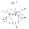
- Fig. 1 shows the arrangement of the exhaust gas heat exchanger based on a schematic diagram.
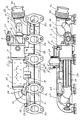
- Fig. 2 shows a preferred variant of the arrangement of the exhaust gas heat exchanger on the exhaust manifold.
- Fig. 3 shows a different from Fig. 2 variant.
- FIG. 4 is a side view similar to FIG. 2.
- FIG. 5 is the plan view of FIG. 4.
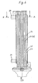
- Fig. 6 is a side view of the exhaust gas heat exchanger without exhaust valve.
- FIG. 7 is the partial section A - A from FIG. 6.
- FIG. 7 is the partial section A - A from FIG. 6.
- FIG. 8 is a view according to arrow B of FIG. 6.
- FIG. 8 is a view according to arrow B of FIG. 6.
- the invention has been implemented in a diesel internal combustion engine 6.
- the exhaust gas heat exchanger 1 is located on the exhaust manifold 2 of the cylinder bank.
- the uncooled exhaust gases can flow to return via the return line 3 back to the intake manifold S of the internal combustion engine 6, where it with the mixed fresh air supplied by the exhaust gas turbocharger ATL and a further combustion in the cylinders of the internal combustion engine 6 are supplied.
- the embodiment of Fig. 1 shows that the fresh air is previously sent through the intercooler LLK to be cooled as needed.
- the other terminal 17 between the opposite side of the exhaust gas heat exchanger 1 and the exhaust manifold 2 is arranged in the region of the first branch Z1.
- connection 17 flows - at the corresponding position of the switching flap 5 of the exhaust valve 4, the exhaust gas to be cooled in the exhaust gas heat exchanger 1 to be cooled by means of the cooling liquid of the internal combustion engine 6 and then returned via the return line 3, as described.
- Fig. 2 corresponds to the variant shown in Fig. 1, wherein it shows how the exhaust valve 4 is constructed. It has an inflow channel 7 for incoming via the terminal 15 uncooled exhaust gases. In this case, the switching flap 5 is in a position in which the inflow channel 7 is connected to the outflow channel 9 and the inflow channel 8 is closed. The exhaust gas enters the return line 3 and back to the suction side S.
- the inflow channels 7 and 8 are arranged approximately in a line. They represent approximately the extension of the exhaust gas flow channels 26 within the exhaust gas heat exchanger 1.
- the outflow channel 9 is approximately perpendicular to the aforementioned channels 7 and 8.
- FIGS. 1 and 2 are preferred variants, because the efficiency of the exhaust gas recirculation is improved without cooling.
- FIG. 3 it can be seen that the exhaust valve 4 has been arranged on the opposite side of the exhaust gas heat exchanger 1. At the inlet channel 7 of the exhaust valve 4, the terminal 15 has been arranged here, which leads to the exhaust manifold 2 with the exhaust manifold 10. The opening 13 in the exhaust manifold 2 is located approximately in the region of the first branch Z1. At this opening 13 of the exhaust manifold 10 is flanged or otherwise connected.
- the exhaust manifold (10) is a balgumblener part 22, which serves to compensate for the material expansion, because it is expected to extremely high temperature fluctuations, which must be taken into account throughout the assembly, especially in the execution of the exhaust valve 4.
- the exhaust gas heat exchanger 1 flows through only in the direction of the exhaust valve 4 with the exhaust gas.
- the total length L of the exhaust manifold 2 has been drawn.
- the opening 14 in FIG. 3 or the opening 13 in FIG. 2 should preferably not be further than 1/3 of the total length L from the outlet 12 of the exhaust gases.
- both possible positions of the actuator 5 have been drawn. In the current position in FIG.
- the inflow channel 7 is closed, so that the exhaust gas flowing through the exhaust gas heat exchanger 1 can flow in via the inflow channel 8 and can reach the return line 3 via the outflow channel 9.
- the inflow channel 8 is closed and the inflow channel 7 is opened, so that, accordingly, the exhaust gas passes into the return line 3 without being cooled.
- the exhaust manifold 2 here also has five series-arranged branches Z1 to Z5, which are each provided with a flange to be connected to the cylinder heads, not shown, of the internal combustion engine 6. It consists of two deformed half-shells, which are connected in the longitudinal direction of the exhaust manifold 2, which is indicated by the thick line in Fig. 4. Furthermore, the exhaust manifold 2 also includes a connection manifold 23, which has an outlet 12 which leads in the embodiment to the exhaust gas turbocharger ATL, which is arranged in a compact design of the internal combustion engine 6 directly at the outlet 12.
- the flow of the exhaust gases is illustrated by arrows, the dashed arrows are to show the partial flow of the exhaust gases, which is returned and cooled as needed and the arrows with solid lines show the main flow of exhaust gases to the exhaust gas turbocharger ATL.
- the exhaust gas heat exchanger 1 is arranged very close to the exhaust manifold 2 and approximately parallel thereto.
- the connecting piece 11 leads to the opening 13, which is located in the connection manifold 23 and thus extremely close to the exit 12 of the exhaust gases, whereby the forming backlog of exhaust gases is effectively used to uncooled exhaust gases to convey the exhaust valve 4 in the return line 3.
- the return line 3 has in this embodiment also has a flange 21 to secure a continuation of the line.
- the connecting piece 10 is fastened with its flange 20 at the opening 14 between the first Z 1 and the second branch Z 2 to the cylinder heads, not shown, on one side.
- the connecting piece 10 leads to the connection 17 of the exhaust gas heat exchanger 1.
- the position of the opening 14, however, can be chosen relatively freely. Not another shown embodiment has the opening 14 approximately in the middle of the exhaust manifold 2, because a much smaller or shorter exhaust heat exchanger 2 can be used.
- the exhaust gas heat exchanger 1 has been attached by means of additional holders 18 and 19 to the exhaust manifold 2.
- the exhaust gas heat exchanger 1 is a housing-free plate heat exchanger in which the exhaust gas is cooled by thedenierleit the internal combustion engine 6. As also shown in FIGS. 6, 7 and 8, the exhaust gas heat exchanger 1 has two connections 24 for the cooling liquid. These can be z. B. in over the edge of the heat exchanger plates 25 cantilevered areas 28 may be arranged. The heat exchanger plates 25 are deformed in such a way that they can be stacked on or into each other, forming alternating flow channels 27 for the cooling liquid and 26 for the exhaust gas.
- the details are state of the art and need not be described in detail here.
- the heat exchanger plates 25 may be made of stainless steel. They are connected by soldering to form a compact and externally sealed body. In the channels 26 are relatively smooth vanes 29, which provide turbulence of the exhaust gases and thus improved heat exchange, but without causing problems with the deposition of residues of the exhaust gas, and to lead to the sooting of the channels 26.
- the heat exchanger plates 25 have a bead 32 to be designated as encircling characteristic. They lie with their peripheral shapes 32 on each other and thereby form the flow channels 27 for the cooling liquid.
- Figure 7 the path through the exhaust gas heat exchanger 1, which describes the cooling liquid, has been shown by arrows. 6, in which the exhaust valve 4 has been omitted, it adjoins the upper edge of the image, shows that the length of the flow channels for the exhaust gas 26 is greater than the length of the flow channels 27 for the cooling liquid.
- the exhaust gas flows in the direction of arrow B through the channels 26 to the exhaust valve 4, not shown, and from there on, as already described. Further details are described in the aforementioned German Patent Application No. 198 46 518.1 1
Landscapes
- Engineering & Computer Science (AREA)
- Mechanical Engineering (AREA)
- General Engineering & Computer Science (AREA)
- Chemical & Material Sciences (AREA)
- Combustion & Propulsion (AREA)
- Physics & Mathematics (AREA)
- Thermal Sciences (AREA)
- Exhaust-Gas Circulating Devices (AREA)
- Exhaust Silencers (AREA)
- Heat-Exchange Devices With Radiators And Conduit Assemblies (AREA)
Claims (11)
- Ensemble de recirculation de gaz d'échappement comprenant un échangeur de chaleur de gaz d'échappement (1) pour moteurs à combustion interne (6) avec une barre collectrice de gaz d'échappement (2) et une conduite de recirculation de gaz d'échappement (3) et comprenant une soupape de gaz d'échappement (4) présentant des canaux d'entrée et de sortie et un actionneur (5), par exemple fixée d'un côté de l'échangeur de chaleur de gaz d'échappement (1) ou formant une unité constructive avec l'échangeur de chaleur de gaz d'échappement (1), ou seulement disposée à proximité spatiale de l'échangeur de chaleur de gaz d'échappement (1), la soupape de gaz d'échappement (4) conduisant une partie du courant de gaz d'échappement soit à travers l'échangeur de chaleur de gaz d'échappement (1) dans la conduite de recirculation de gaz d'échappement (3), soit directement dans la conduite de recirculation de gaz d'échappement (3) jusqu'au tuyau d'admission du moteur à combustion interne (6) et la barre collectrice de gaz d'échappement (2) présentant des dérivations (Z1-Z5) au niveau des culasses du moteur à combustion interne (6) et une sortie (12), par exemple vers une turbosoufflante à gaz d'échappement (ATL),
caractérisé en ce que
l'échangeur de chaleur de gaz d'échappement (1) est raccordé à deux ouvertures (13, 14) dans la barre collectrice de gaz d'échappement (2) présentant des raccords (15, 17), la soupape de gaz d'échappement (4) étant disposée entre l'une des ouvertures (13) et un côté de l'échangeur de chaleur de gaz d'échappement (1) et l'autre côté de l'échangeur de chaleur de gaz d'échappement (1) étant en liaison avec l'autre ouverture (14) et au moins l'une des ouvertures (13 ou 14) étant prévue dans la région de refoulement (SB) des gaz d'échappement avant leur sortie (12), vu dans le sens de l'écoulement des gaz d'échappement, la région de refoulement (SB) ne revenant pas depuis la sortie (12) plus loin que la moitié de la longueur totale de la barre collectrice de gaz d'échappement (2). - Echangeur de chaleur de gaz d'échappement selon la revendication 1, caractérisé en ce que l'une des ouvertures (13) présente le raccord (15) au canal d'entrée (7) de la soupape de gaz d'échappement (4), et est l'ouverture qui se situe dans la région de refoulement (SB) des gaz d'échappement, à travers laquelle s'écoule le gaz d'échappement non refroidi à recirculer et en ce que l'autre ouverture (14) dans la barre collectrice de gaz d'échappement (2), qui présente le raccord (17) à l'autre côté, opposé, de l'échangeur de chaleur de gaz d'échappement (1), est celle à travers laquelle le gaz d'échappement à refroidir et à recirculer s'écoule dans l'échangeur de chaleur de gaz d'échappement (1).
- Echangeur de chaleur de gaz d'échappement selon la revendication 1 ou 2, caractérisé en ce que l'échangeur de chaleur de gaz d'échappement (1) peut être parcouru par le gaz d'échappement en direction de la soupape de gaz d'échappement (4).
- Echangeur de chaleur de gaz d'échappement selon les revendications 1, 2 ou 3, caractérisé en ce que l'échangeur de chaleur de gaz d'échappement (1) peut être fixé en outre au moyen de fixations (18, 19) sur la barre collectrice de gaz d'échappement (2).
- Echangeur de chaleur de gaz d'échappement selon l'une quelconque des revendications précédentes, caractérisé en ce qu'au moins l'ouverture (13) pour les gaz d'échappement non refroidis à recirculer est disposée de préférence à 1/3 de la longueur totale (L) de la barre collectrice de gaz d'échappement (2), à distance de la sortie (12), la sortie (12) se trouvant à l'extrémité d'un collecteur de raccordement (23) dans lequel est disposée de préférence l'ouverture (13).
- Echangeur de chaleur de gaz d'échappement selon l'une quelconque des revendications précédentes, caractérisé en ce que l'ouverture (14) pour les gaz d'échappement à refroidir à recirculer, vue dans le sens de l'écoulement des gaz d'échappement, est prévue approximativement dans la région entre la première et la deuxième dérivation (Z1 ; Z2) vers les cylindres du moteur à combustion interne (6) dans la barre collectrice de gaz d'échappement (2), mais pourrait aussi être disposée approximativement au milieu de la longueur totale (L) de la barre collectrice de gaz d'échappement (2).
- Echangeur de chaleur de gaz d'échappement selon l'une quelconque des revendications précédentes, caractérisé en ce que les raccords (15, 17) entre la barre collectrice de gaz d'échappement (2) et l'échangeur de chaleur de gaz d'échappement (1) ou la soupape de gaz d'échappement (4) sont de courtes tubulures de raccordement (10, 11) qui sont munies de brides de raccordement (20, 21) de sorte que l'échangeur de chaleur de gaz d'échappement (1) soit disposé approximativement parallèlement à la barre collectrice de gaz d'échappement (2) et à faible distance de celle-ci.
- Echangeur de chaleur de gaz d'échappement selon l'une quelconque des revendications précédentes, caractérisé en ce que l'on utilise comme réfrigérant le liquide de refroidissement du moteur à combustion interne (6).
- Echangeur de chaleur de gaz d'échappement selon l'une quelconque des revendications précédentes, caractérisé en ce que la soupape de gaz d'échappement (4) présente un canal d'entrée (7) pour les gaz d'échappement sortant de la barre collectrice de gaz d'échappement (2), un canal d'entrée (8) pour les gaz d'échappement sortant de l'échangeur de chaleur de gaz d'échappement (1) et un canal de sortie (9) pour la conduite de recirculation (3), et possède, à l'intersection desdits canaux, un volet de commutation servant d'actionneur (5) avec lequel l'un ou l'autre canal d'entrée (7, 8) peut être complètement bloqué, le canal de sortie (9) restant constamment ouvert.
- Echangeur de chaleur de gaz d'échappement selon la revendication 9, caractérisé en ce que les deux canaux d'entrée (7, 8) sont disposés approximativement de manière alignée dans la direction longitudinale de l'échangeur de chaleur de gaz d'échappement (1) et le canal de sortie (9) est perpendiculaire à ceux-ci.
- Echangeur de chaleur de gaz d'échappement selon l'une quelconque des revendications précédentes, caractérisé en ce que l'échangeur de chaleur de gaz d'échappement (1) est un échangeur de chaleur à plaques sans boîtier.
Applications Claiming Priority (2)
| Application Number | Priority Date | Filing Date | Title |
|---|---|---|---|
| DE10011954 | 2000-03-11 | ||
| DE10011954A DE10011954A1 (de) | 2000-03-11 | 2000-03-11 | Abgaswärmetauscher in einer Abgasrückführungsanordnung |
Publications (3)
| Publication Number | Publication Date |
|---|---|
| EP1132609A2 EP1132609A2 (fr) | 2001-09-12 |
| EP1132609A3 EP1132609A3 (fr) | 2002-03-20 |
| EP1132609B1 true EP1132609B1 (fr) | 2006-09-27 |
Family
ID=7634392
Family Applications (1)
| Application Number | Title | Priority Date | Filing Date |
|---|---|---|---|
| EP01103422A Expired - Lifetime EP1132609B1 (fr) | 2000-03-11 | 2001-02-14 | Echangeur de chaleur disposé dans un dispositif de recirculation de gaz d'échappement |
Country Status (5)
| Country | Link |
|---|---|
| US (1) | US6360532B2 (fr) |
| EP (1) | EP1132609B1 (fr) |
| AT (1) | ATE340924T1 (fr) |
| DE (2) | DE10011954A1 (fr) |
| ES (1) | ES2273753T3 (fr) |
Families Citing this family (51)
| Publication number | Priority date | Publication date | Assignee | Title |
|---|---|---|---|---|
| DE10153383A1 (de) * | 2001-10-30 | 2003-05-22 | Visteon Global Tech Inc | Abgaswärmerückgewinnungsvorrichtung |
| DE10214467A1 (de) | 2002-03-30 | 2003-10-09 | Modine Mfg Co | Abgaswärmetauscher für Kraftfahrzeuge |
| JP4473116B2 (ja) * | 2002-05-15 | 2010-06-02 | ベール ゲーエムベーハー ウント コー カーゲー | 切換可能な排気熱交換器 |
| US7171956B2 (en) * | 2002-08-28 | 2007-02-06 | T. Rad Co., Ltd. | EGR cooler |
| AT413130B (de) * | 2003-09-23 | 2005-11-15 | Ge Jenbacher Ag | Brennkraftmaschine |
| FR2875540B1 (fr) * | 2004-09-20 | 2007-03-16 | Mark Iv Systemes Moteurs Sa | Module multifonctionnel, vehicule a moteur comportant un tel module et procede de fabrication d'un tel module |
| BRPI0516124A (pt) | 2004-10-07 | 2008-08-26 | Behr Gmbh & Co Kg | trocador de calor de gás de descarga refrigerado a ar, especialmente refrigerador de gás de descarga para veìculos automóveis |
| US7543558B2 (en) | 2004-11-10 | 2009-06-09 | Buck Diesel Engines, Inc. | Multicylinder internal combustion engine with individual cylinder assemblies |
| US7287493B2 (en) * | 2004-11-10 | 2007-10-30 | Buck Supply Co., Inc. | Internal combustion engine with hybrid cooling system |
| US7287494B2 (en) * | 2004-11-10 | 2007-10-30 | Buck Supply Co., Inc. | Multicylinder internal combustion engine with individual cylinder assemblies and modular cylinder carrier |
| GB2420593B (en) * | 2004-11-29 | 2007-04-25 | Gibbs Tech Ltd | An exhaust cooling system of an amphibious vehicle |
| US20070051503A1 (en) * | 2005-09-08 | 2007-03-08 | Grajzl Harold A | Corrosion resistant charge air cooler and method of making same |
| FR2891590B1 (fr) * | 2005-09-30 | 2010-09-17 | Renault Sas | Dispositif de repartition des gaz recircules, refroidisseur de gaz recircules et procede de recirculation de gaz d'echappement. |
| US7131263B1 (en) * | 2005-11-03 | 2006-11-07 | Ford Global Technologies, Llc | Exhaust gas recirculation cooler contaminant removal method and system |
| WO2007098854A1 (fr) * | 2006-02-24 | 2007-09-07 | Behr Gmbh & Co. Kg | Soupape de regulation de l'ecoulement de gaz d'échappement d'un moteur a combustion interne, echangeur de chaleur destine au refroidissement deS gaz d'echappement, systeme dote d'au moins une soupape et d'au moins un echangeur de chaleur |
| US7566423B2 (en) * | 2006-04-26 | 2009-07-28 | Purify Solutions, Inc. | Air purification system employing particle burning |
| US20070240408A1 (en) * | 2006-04-14 | 2007-10-18 | Ewa Environmental, Inc. | Particle burner including a catalyst booster for exhaust systems |
| US20080271448A1 (en) * | 2007-05-03 | 2008-11-06 | Ewa Environmental, Inc. | Particle burner disposed between an engine and a turbo charger |
| US7500359B2 (en) * | 2006-04-26 | 2009-03-10 | Purify Solutions, Inc. | Reverse flow heat exchanger for exhaust systems |
| US20070278199A1 (en) * | 2006-04-14 | 2007-12-06 | Ewa Environmental, Inc. | Particle burning in an exhaust system |
| US20080314035A1 (en) * | 2006-04-14 | 2008-12-25 | Lincoln Evan-Beauchamp | Temperature Ladder and Applications Thereof |
| US7380544B2 (en) * | 2006-05-19 | 2008-06-03 | Modine Manufacturing Company | EGR cooler with dual coolant loop |
| US7610949B2 (en) * | 2006-11-13 | 2009-11-03 | Dana Canada Corporation | Heat exchanger with bypass |
| US7363919B1 (en) * | 2007-01-05 | 2008-04-29 | Ford Global Technologies, Llc | Integrated exhaust gas recirculation valve and cooler system |
| DE102007002856B4 (de) | 2007-01-15 | 2012-02-09 | Edag Gmbh & Co. Kgaa | Vorrichtung zum Bördeln und Schweißen oder Löten von Bauteilen |
| ES2325348B1 (es) * | 2007-04-13 | 2010-04-23 | Valeo Termico, S.A. | Intercambiador de calor para gases, y su correspondiente procedimiento de fabricacion. |
| DE102008001659B4 (de) | 2007-07-11 | 2014-01-30 | Halla Visteon Climate Control Corp. | Abgaswärmetauscher mit integrierter Montageschnittstelle |
| DE102008002430C5 (de) | 2007-07-11 | 2018-03-22 | Hanon Systems | Abgaswärmetauscher mit schwingungsgedämpftem Tauscher-Rohrbündel |
| DE102008001660B4 (de) | 2007-07-11 | 2025-03-06 | Hanon Systems | Wärmetauscher |
| DE102008002746A1 (de) | 2007-07-11 | 2009-02-12 | Visteon Global Technologies Inc., Van Buren | Wärmetauscher für den Abgasstrang eines Kraftfahrzeugs, Verfahren zur Herstellung eines Wärmetauschers sowie Montagewerkzeug hierzu |
| DE102007033679B4 (de) * | 2007-07-19 | 2009-07-09 | Mtu Friedrichshafen Gmbh | Abgasleitung einer Brennkraftmaschine |
| DE102007053126B4 (de) | 2007-11-08 | 2018-08-02 | Bayerische Motoren Werke Aktiengesellschaft | Brennkraftmaschine mit gekühlter Abgasrückführung sowie Abgaskrümmer |
| DE102008008697A1 (de) * | 2008-02-11 | 2009-08-27 | Behr Gmbh & Co. Kg | Aktuator für eine Bypass-Regeleinrichtung eines Bypasses bei einem Wärmetauscher, Wärmetauscher oder Baueinheit mit einem oder mehreren Wärmetauschern, Bypasssystem, Fahrzeugdiagnosesystem, Abgasrückführsystem, Ladeluftzuführsystem und Verwendung des Wärmetauschers oder der Baueinheit |
| WO2009114568A2 (fr) * | 2008-03-13 | 2009-09-17 | Borgwarner Inc. | Tubulure d’échappement d’un moteur à combustion interne |
| US8176885B2 (en) * | 2008-08-25 | 2012-05-15 | Cummins Intellectual Properties, Inc. | Cooling system with fouling reducing element |
| DE102009000263B4 (de) | 2009-01-15 | 2016-09-08 | Halla Visteon Climate Control Corporation | Wärmetauscher für den Abgasstrang eines Kraftfahrzeugs mit verbessertem Temperaturausgleich im Kühlmittel |
| US20100229540A1 (en) * | 2009-03-11 | 2010-09-16 | Indmar Products Company Inc. | Combination Liquid-Cooled Exhaust Manifold Assembly And Catalytic Converter Assembly For A Marine Engine |
| US8316814B2 (en) * | 2009-06-29 | 2012-11-27 | Buck Kenneth M | Toploading internal combustion engine |
| JP5575533B2 (ja) * | 2010-04-28 | 2014-08-20 | ヤンマー株式会社 | 排気マニホールド |
| DE102010048793B3 (de) * | 2010-10-20 | 2011-11-17 | Pierburg Gmbh | Abgasführungsvorrichtung für eine Verbrennungskraftmaschine |
| DE102011109264A1 (de) * | 2011-08-03 | 2013-02-07 | Man Truck & Bus Ag | Abgasrückführeinrichtung für eine Brennkraftmaschine eines Fahrzeuges sowie Verfahren zum Betreiben einer Abgasrückführeinrichtung |
| KR20140075710A (ko) | 2011-09-09 | 2014-06-19 | 다나 캐나다 코포레이션 | 적층된 플레이트 배기 가스 회수 장치 |
| DE102012223808B4 (de) | 2012-01-05 | 2019-06-13 | Ford Global Technologies, Llc | Brennkraftmaschine mit Abgasturboaufladung und Abgasrückführung und Verfahren zum Betreiben einer derartigen Brennkraftmaschine |
| US20140238363A1 (en) * | 2013-02-26 | 2014-08-28 | GM Global Technology Operations LLC | Exhaust gas recirculation system |
| US9989322B2 (en) | 2013-03-01 | 2018-06-05 | Dana Canada Corporation | Heat recovery device with improved lightweight flow coupling chamber and insertable valve |
| US10352278B2 (en) * | 2016-08-19 | 2019-07-16 | Ge Global Sourcing Llc | Method and systems for an exhaust gas recirculation cooler including two sections |
| JP7159806B2 (ja) * | 2018-11-21 | 2022-10-25 | トヨタ自動車株式会社 | 熱交換器 |
| CN110030066A (zh) * | 2019-05-16 | 2019-07-19 | 杰锋汽车动力系统股份有限公司 | 一种汽车尾气余热回收再利用系统 |
| US11486337B2 (en) * | 2019-09-06 | 2022-11-01 | Deere & Company | Integrated exhaust system apparatus |
| JP7260466B2 (ja) * | 2019-12-31 | 2023-04-18 | 株式会社クボタ | 産業用エンジンの排気マニホルド及び産業用エンジン |
| DE102020000965A1 (de) | 2020-02-14 | 2021-08-19 | Daimler Ag | Verbrennungskraftmaschine für ein Kraftfahrzeug, insbesondere für einen Kraftwagen |
Family Cites Families (12)
| Publication number | Priority date | Publication date | Assignee | Title |
|---|---|---|---|---|
| SE506125C2 (sv) * | 1994-12-08 | 1997-11-10 | Scania Cv Ab | Arrangemang för återledning av avgaser i överladdade motorer med parallella turbiner |
| US5785030A (en) * | 1996-12-17 | 1998-07-28 | Dry Systems Technologies | Exhaust gas recirculation in internal combustion engines |
| US5806308A (en) * | 1997-07-07 | 1998-09-15 | Southwest Research Institute | Exhaust gas recirculation system for simultaneously reducing NOx and particulate matter |
| JP3901303B2 (ja) | 1997-10-28 | 2007-04-04 | 日本碍子株式会社 | ヒーターユニット |
| FR2770582B1 (fr) * | 1997-10-31 | 2000-01-28 | Valeo Thermique Moteur Sa | Ligne d'echappement et de recirculation des gaz pour moteur de vehicule automobile |
| DE19750588B4 (de) * | 1997-11-17 | 2016-10-13 | MAHLE Behr GmbH & Co. KG | Vorrichtung zur Abgasrückführung für einen Verbrennungsmotor |
| DE29722813U1 (de) * | 1997-12-24 | 1999-04-22 | Behr Thermot-Tronik Gmbh & Co., 70806 Kornwestheim | Abgasrückführungseinrichtung für einen Verbrennungsmotor eines Kraftfahrzeuges |
| JPH11280565A (ja) * | 1998-03-31 | 1999-10-12 | Isuzu Motors Ltd | Egr装置 |
| DE19841927A1 (de) * | 1998-09-14 | 2000-03-16 | Wahler Gmbh & Co Gustav | Einrichtung zur Rückführung eines Abgasstromes zum Saugrohr einer Brennkraftmaschine |
| US6116026A (en) * | 1998-12-18 | 2000-09-12 | Detroit Diesel Corporation | Engine air intake manifold having built-in intercooler |
| DE19906401C1 (de) * | 1999-02-16 | 2000-08-31 | Ranco Inc Of Delaware Wilmingt | Abgasrückführsystem |
| US6176082B1 (en) * | 1999-04-21 | 2001-01-23 | Caterpillar Inc. | Exhaust manifold cooling assembly for an internal combustion engine |
-
2000
- 2000-03-11 DE DE10011954A patent/DE10011954A1/de not_active Withdrawn
-
2001
- 2001-02-06 US US09/777,326 patent/US6360532B2/en not_active Expired - Fee Related
- 2001-02-14 AT AT01103422T patent/ATE340924T1/de not_active IP Right Cessation
- 2001-02-14 DE DE50111065T patent/DE50111065D1/de not_active Expired - Lifetime
- 2001-02-14 ES ES01103422T patent/ES2273753T3/es not_active Expired - Lifetime
- 2001-02-14 EP EP01103422A patent/EP1132609B1/fr not_active Expired - Lifetime
Also Published As
| Publication number | Publication date |
|---|---|
| US6360532B2 (en) | 2002-03-26 |
| EP1132609A3 (fr) | 2002-03-20 |
| ATE340924T1 (de) | 2006-10-15 |
| US20010020363A1 (en) | 2001-09-13 |
| DE10011954A1 (de) | 2001-09-13 |
| ES2273753T3 (es) | 2007-05-16 |
| DE50111065D1 (de) | 2006-11-09 |
| EP1132609A2 (fr) | 2001-09-12 |
Similar Documents
| Publication | Publication Date | Title |
|---|---|---|
| EP1132609A2 (fr) | Echangeur de chaleur disposé dans un dispositif de recirculation de gaz d'échappement | |
| DE10203003B4 (de) | Abgaswärmeübertrager | |
| EP2159394B1 (fr) | Refroidisseur de gaz d'échappement pour un moteur à combustion | |
| EP1671020B1 (fr) | Echangeur air / air du moteur turbo d'un vehicule | |
| DE60107748T2 (de) | Brennkraftmaschine mit Abgasrückführungssystem, insbesondere für Fahrzeuge | |
| DE4240239C2 (de) | Verbrennungskraftmaschine | |
| EP2419615B1 (fr) | Canal d'air de suralimentation pour moteur à combustion interne | |
| EP1491837B1 (fr) | Echangeur de chaleur à plaques sans enveloppe | |
| EP2020501B1 (fr) | Boîtier d'échangeur thermique, échangeur thermique ou composant doté d'un ou plusieurs échangeurs thermiques, système de récupération des gaz d'échappement, système d'alimentation en air de suralimentation et utilisation de l'échangeur thermique | |
| EP2302190B1 (fr) | Système de refoulement des gaz d'échappement | |
| EP1604163A1 (fr) | Echangeur thermique, notamment refroidisseur de gaz d'echappement pour automobiles | |
| EP2077387B1 (fr) | Procédé destiné au refroidissement d'un flux des gaz d'échappement recyclé d'un moteur à combustion interne | |
| EP1941224A1 (fr) | Echangeur thermique | |
| EP1857761B1 (fr) | Unité de transmission de la chaleur pour moteurs à combustion interne | |
| DE10328846C5 (de) | Wärmetauscher | |
| EP2209983A1 (fr) | Module multifonctionnel à monter sur un moteur à combustion interne pour acheminer des fluides sous forme de gaz d'échappement et de fluides de refroidissement, agencement comprenant ce module et moteur à combustion interne | |
| WO2008101978A1 (fr) | Module de gaz frais conçu pour une installation de gaz frais | |
| EP2863157A1 (fr) | Échangeur de chaleur | |
| EP2048345B1 (fr) | Echangeur thermique, notamment destiné au refroidissement des gaz d'échappement | |
| DE102006049106A1 (de) | Wärmetauscher | |
| EP1843116A2 (fr) | Échangeur de chaleur à plaques empilées | |
| WO2008058737A1 (fr) | Dispositif de recyclage des gaz d'échappement | |
| DE102015206893B4 (de) | Abgasrückführungsmodul mit gekühltem Abgasrückführungsventil | |
| EP1746263B1 (fr) | Système de soupape pour un échangeur de chaleur | |
| DE102007016355A1 (de) | Stapelscheibenwärmeübertrager |
Legal Events
| Date | Code | Title | Description |
|---|---|---|---|
| PUAI | Public reference made under article 153(3) epc to a published international application that has entered the european phase |
Free format text: ORIGINAL CODE: 0009012 |
|
| AK | Designated contracting states |
Kind code of ref document: A2 Designated state(s): AT BE CH CY DE DK ES FI FR GB GR IE IT LI LU MC NL PT SE TR |
|
| AX | Request for extension of the european patent |
Free format text: AL;LT;LV;MK;RO;SI |
|
| PUAL | Search report despatched |
Free format text: ORIGINAL CODE: 0009013 |
|
| AK | Designated contracting states |
Kind code of ref document: A3 Designated state(s): AT BE CH CY DE DK ES FI FR GB GR IE IT LI LU MC NL PT SE TR |
|
| AX | Request for extension of the european patent |
Free format text: AL;LT;LV;MK;RO;SI |
|
| 17P | Request for examination filed |
Effective date: 20020920 |
|
| AKX | Designation fees paid |
Free format text: AT BE CH CY DE DK ES FI FR GB GR IE IT LI LU MC NL PT SE TR |
|
| GRAP | Despatch of communication of intention to grant a patent |
Free format text: ORIGINAL CODE: EPIDOSNIGR1 |
|
| GRAS | Grant fee paid |
Free format text: ORIGINAL CODE: EPIDOSNIGR3 |
|
| GRAA | (expected) grant |
Free format text: ORIGINAL CODE: 0009210 |
|
| AK | Designated contracting states |
Kind code of ref document: B1 Designated state(s): AT BE CH CY DE DK ES FI FR GB GR IE IT LI LU MC NL PT SE TR |
|
| PG25 | Lapsed in a contracting state [announced via postgrant information from national office to epo] |
Ref country code: IT Free format text: LAPSE BECAUSE OF FAILURE TO SUBMIT A TRANSLATION OF THE DESCRIPTION OR TO PAY THE FEE WITHIN THE PRESCRIBED TIME-LIMIT;WARNING: LAPSES OF ITALIAN PATENTS WITH EFFECTIVE DATE BEFORE 2007 MAY HAVE OCCURRED AT ANY TIME BEFORE 2007. THE CORRECT EFFECTIVE DATE MAY BE DIFFERENT FROM THE ONE RECORDED. Effective date: 20060927 Ref country code: IE Free format text: LAPSE BECAUSE OF FAILURE TO SUBMIT A TRANSLATION OF THE DESCRIPTION OR TO PAY THE FEE WITHIN THE PRESCRIBED TIME-LIMIT Effective date: 20060927 Ref country code: NL Free format text: LAPSE BECAUSE OF FAILURE TO SUBMIT A TRANSLATION OF THE DESCRIPTION OR TO PAY THE FEE WITHIN THE PRESCRIBED TIME-LIMIT Effective date: 20060927 Ref country code: FI Free format text: LAPSE BECAUSE OF FAILURE TO SUBMIT A TRANSLATION OF THE DESCRIPTION OR TO PAY THE FEE WITHIN THE PRESCRIBED TIME-LIMIT Effective date: 20060927 |
|
| REG | Reference to a national code |
Ref country code: GB Ref legal event code: FG4D Free format text: NOT ENGLISH |
|
| REG | Reference to a national code |
Ref country code: CH Ref legal event code: EP |
|
| REG | Reference to a national code |
Ref country code: IE Ref legal event code: FG4D Free format text: LANGUAGE OF EP DOCUMENT: GERMAN |
|
| REF | Corresponds to: |
Ref document number: 50111065 Country of ref document: DE Date of ref document: 20061109 Kind code of ref document: P |
|
| PG25 | Lapsed in a contracting state [announced via postgrant information from national office to epo] |
Ref country code: DK Free format text: LAPSE BECAUSE OF FAILURE TO SUBMIT A TRANSLATION OF THE DESCRIPTION OR TO PAY THE FEE WITHIN THE PRESCRIBED TIME-LIMIT Effective date: 20061227 |
|
| REG | Reference to a national code |
Ref country code: SE Ref legal event code: TRGR |
|
| GBT | Gb: translation of ep patent filed (gb section 77(6)(a)/1977) |
Effective date: 20070103 |
|
| PG25 | Lapsed in a contracting state [announced via postgrant information from national office to epo] |
Ref country code: CH Free format text: LAPSE BECAUSE OF NON-PAYMENT OF DUE FEES Effective date: 20070228 Ref country code: MC Free format text: LAPSE BECAUSE OF NON-PAYMENT OF DUE FEES Effective date: 20070228 Ref country code: LI Free format text: LAPSE BECAUSE OF NON-PAYMENT OF DUE FEES Effective date: 20070228 |
|
| NLV1 | Nl: lapsed or annulled due to failure to fulfill the requirements of art. 29p and 29m of the patents act | ||
| PG25 | Lapsed in a contracting state [announced via postgrant information from national office to epo] |
Ref country code: PT Free format text: LAPSE BECAUSE OF FAILURE TO SUBMIT A TRANSLATION OF THE DESCRIPTION OR TO PAY THE FEE WITHIN THE PRESCRIBED TIME-LIMIT Effective date: 20070313 |
|
| REG | Reference to a national code |
Ref country code: IE Ref legal event code: FD4D |
|
| ET | Fr: translation filed | ||
| REG | Reference to a national code |
Ref country code: ES Ref legal event code: FG2A Ref document number: 2273753 Country of ref document: ES Kind code of ref document: T3 |
|
| PLBE | No opposition filed within time limit |
Free format text: ORIGINAL CODE: 0009261 |
|
| STAA | Information on the status of an ep patent application or granted ep patent |
Free format text: STATUS: NO OPPOSITION FILED WITHIN TIME LIMIT |
|
| 26N | No opposition filed |
Effective date: 20070628 |
|
| REG | Reference to a national code |
Ref country code: CH Ref legal event code: PL |
|
| BERE | Be: lapsed |
Owner name: MODINE MANUFACTURING CY Effective date: 20070228 |
|
| PG25 | Lapsed in a contracting state [announced via postgrant information from national office to epo] |
Ref country code: BE Free format text: LAPSE BECAUSE OF NON-PAYMENT OF DUE FEES Effective date: 20070228 |
|
| PG25 | Lapsed in a contracting state [announced via postgrant information from national office to epo] |
Ref country code: GR Free format text: LAPSE BECAUSE OF FAILURE TO SUBMIT A TRANSLATION OF THE DESCRIPTION OR TO PAY THE FEE WITHIN THE PRESCRIBED TIME-LIMIT Effective date: 20061228 |
|
| PG25 | Lapsed in a contracting state [announced via postgrant information from national office to epo] |
Ref country code: AT Free format text: LAPSE BECAUSE OF NON-PAYMENT OF DUE FEES Effective date: 20070214 |
|
| PG25 | Lapsed in a contracting state [announced via postgrant information from national office to epo] |
Ref country code: CY Free format text: LAPSE BECAUSE OF FAILURE TO SUBMIT A TRANSLATION OF THE DESCRIPTION OR TO PAY THE FEE WITHIN THE PRESCRIBED TIME-LIMIT Effective date: 20060927 Ref country code: LU Free format text: LAPSE BECAUSE OF NON-PAYMENT OF DUE FEES Effective date: 20070214 |
|
| PG25 | Lapsed in a contracting state [announced via postgrant information from national office to epo] |
Ref country code: TR Free format text: LAPSE BECAUSE OF FAILURE TO SUBMIT A TRANSLATION OF THE DESCRIPTION OR TO PAY THE FEE WITHIN THE PRESCRIBED TIME-LIMIT Effective date: 20060927 |
|
| PGFP | Annual fee paid to national office [announced via postgrant information from national office to epo] |
Ref country code: SE Payment date: 20140224 Year of fee payment: 14 |
|
| PGFP | Annual fee paid to national office [announced via postgrant information from national office to epo] |
Ref country code: ES Payment date: 20140212 Year of fee payment: 14 Ref country code: FR Payment date: 20140224 Year of fee payment: 14 Ref country code: IT Payment date: 20140221 Year of fee payment: 14 |
|
| PGFP | Annual fee paid to national office [announced via postgrant information from national office to epo] |
Ref country code: GB Payment date: 20140224 Year of fee payment: 14 |
|
| PGFP | Annual fee paid to national office [announced via postgrant information from national office to epo] |
Ref country code: DE Payment date: 20150224 Year of fee payment: 15 |
|
| REG | Reference to a national code |
Ref country code: SE Ref legal event code: EUG |
|
| GBPC | Gb: european patent ceased through non-payment of renewal fee |
Effective date: 20150214 |
|
| REG | Reference to a national code |
Ref country code: FR Ref legal event code: ST Effective date: 20151030 |
|
| PG25 | Lapsed in a contracting state [announced via postgrant information from national office to epo] |
Ref country code: SE Free format text: LAPSE BECAUSE OF NON-PAYMENT OF DUE FEES Effective date: 20150215 |
|
| PG25 | Lapsed in a contracting state [announced via postgrant information from national office to epo] |
Ref country code: IT Free format text: LAPSE BECAUSE OF NON-PAYMENT OF DUE FEES Effective date: 20150214 |
|
| PG25 | Lapsed in a contracting state [announced via postgrant information from national office to epo] |
Ref country code: GB Free format text: LAPSE BECAUSE OF NON-PAYMENT OF DUE FEES Effective date: 20150214 |
|
| PG25 | Lapsed in a contracting state [announced via postgrant information from national office to epo] |
Ref country code: FR Free format text: LAPSE BECAUSE OF NON-PAYMENT OF DUE FEES Effective date: 20150302 |
|
| REG | Reference to a national code |
Ref country code: ES Ref legal event code: FD2A Effective date: 20160330 |
|
| PG25 | Lapsed in a contracting state [announced via postgrant information from national office to epo] |
Ref country code: ES Free format text: LAPSE BECAUSE OF NON-PAYMENT OF DUE FEES Effective date: 20150215 |
|
| REG | Reference to a national code |
Ref country code: DE Ref legal event code: R119 Ref document number: 50111065 Country of ref document: DE |
|
| PG25 | Lapsed in a contracting state [announced via postgrant information from national office to epo] |
Ref country code: DE Free format text: LAPSE BECAUSE OF NON-PAYMENT OF DUE FEES Effective date: 20160901 |