EP1132628A2 - Dispositif de positionnement de pièces grâce à une broche de centrage - Google Patents
Dispositif de positionnement de pièces grâce à une broche de centrage Download PDFInfo
- Publication number
- EP1132628A2 EP1132628A2 EP01302143A EP01302143A EP1132628A2 EP 1132628 A2 EP1132628 A2 EP 1132628A2 EP 01302143 A EP01302143 A EP 01302143A EP 01302143 A EP01302143 A EP 01302143A EP 1132628 A2 EP1132628 A2 EP 1132628A2
- Authority
- EP
- European Patent Office
- Prior art keywords
- piston
- housing
- pin
- piston rod
- chamber
- Prior art date
- Legal status (The legal status is an assumption and is not a legal conclusion. Google has not performed a legal analysis and makes no representation as to the accuracy of the status listed.)
- Withdrawn
Links
- 239000012530 fluid Substances 0.000 claims abstract description 27
- 238000007789 sealing Methods 0.000 claims abstract description 3
- 230000002093 peripheral effect Effects 0.000 claims description 4
- 238000004519 manufacturing process Methods 0.000 claims description 3
- 230000000994 depressogenic effect Effects 0.000 claims description 2
- 238000000034 method Methods 0.000 claims 4
- 238000003754 machining Methods 0.000 claims 1
- 230000014759 maintenance of location Effects 0.000 abstract description 2
- 229910052751 metal Inorganic materials 0.000 description 3
- 239000002184 metal Substances 0.000 description 3
- 229910000831 Steel Inorganic materials 0.000 description 2
- 238000004806 packaging method and process Methods 0.000 description 2
- 239000010959 steel Substances 0.000 description 2
- 239000000853 adhesive Substances 0.000 description 1
- 230000001070 adhesive effect Effects 0.000 description 1
- 229910052782 aluminium Inorganic materials 0.000 description 1
- XAGFODPZIPBFFR-UHFFFAOYSA-N aluminium Chemical compound [Al] XAGFODPZIPBFFR-UHFFFAOYSA-N 0.000 description 1
- 238000004891 communication Methods 0.000 description 1
- 239000000463 material Substances 0.000 description 1
- 238000012986 modification Methods 0.000 description 1
- 230000004048 modification Effects 0.000 description 1
Images




Classifications
-
- F—MECHANICAL ENGINEERING; LIGHTING; HEATING; WEAPONS; BLASTING
- F15—FLUID-PRESSURE ACTUATORS; HYDRAULICS OR PNEUMATICS IN GENERAL
- F15B—SYSTEMS ACTING BY MEANS OF FLUIDS IN GENERAL; FLUID-PRESSURE ACTUATORS, e.g. SERVOMOTORS; DETAILS OF FLUID-PRESSURE SYSTEMS, NOT OTHERWISE PROVIDED FOR
- F15B15/00—Fluid-actuated devices for displacing a member from one position to another; Gearing associated therewith
- F15B15/20—Other details, e.g. assembly with regulating devices
- F15B15/28—Means for indicating the position, e.g. end of stroke
- F15B15/2807—Position switches, i.e. means for sensing of discrete positions only, e.g. limit switches
-
- F—MECHANICAL ENGINEERING; LIGHTING; HEATING; WEAPONS; BLASTING
- F15—FLUID-PRESSURE ACTUATORS; HYDRAULICS OR PNEUMATICS IN GENERAL
- F15B—SYSTEMS ACTING BY MEANS OF FLUIDS IN GENERAL; FLUID-PRESSURE ACTUATORS, e.g. SERVOMOTORS; DETAILS OF FLUID-PRESSURE SYSTEMS, NOT OTHERWISE PROVIDED FOR
- F15B15/00—Fluid-actuated devices for displacing a member from one position to another; Gearing associated therewith
- F15B15/08—Characterised by the construction of the motor unit
- F15B15/14—Characterised by the construction of the motor unit of the straight-cylinder type
- F15B15/1414—Characterised by the construction of the motor unit of the straight-cylinder type with non-rotatable piston
- F15B15/1419—Characterised by the construction of the motor unit of the straight-cylinder type with non-rotatable piston of non-circular cross-section
-
- Y—GENERAL TAGGING OF NEW TECHNOLOGICAL DEVELOPMENTS; GENERAL TAGGING OF CROSS-SECTIONAL TECHNOLOGIES SPANNING OVER SEVERAL SECTIONS OF THE IPC; TECHNICAL SUBJECTS COVERED BY FORMER USPC CROSS-REFERENCE ART COLLECTIONS [XRACs] AND DIGESTS
- Y10—TECHNICAL SUBJECTS COVERED BY FORMER USPC
- Y10S—TECHNICAL SUBJECTS COVERED BY FORMER USPC CROSS-REFERENCE ART COLLECTIONS [XRACs] AND DIGESTS
- Y10S294/00—Handling: hand and hoist-line implements
- Y10S294/907—Sensor controlled device
Definitions
- This invention relates generally to fluid powered devices and more particularly to a fluid powered, part locator.
- one conventional pin part locator employs a pneumatically driven piston, having an oval peripheral shape, which advances and retracts an elongated piston rod connected to a tapered workpiece locating pin.
- the tolerances and accuracy of the piston rod and locator pin relative to the body are poor and can vary by as much as plus or minus one-half degree from the desired centerline. This type of inaccuracy is even further accentuated when employed to locate or orient sheet metal panels on an automotive vehicle assembly line when a small tolerance mismatch at the bottom of the vehicle may accumulate to a considerable tolerance stack-up at the vehicle's roof.
- proximity switches with pneumatically powered industrial devices such as pin part locators, powered clamps and robotic grippers.
- pneumatically powered industrial devices such as pin part locators, powered clamps and robotic grippers.
- the proximity switches are mounted in optional fluid ports and protrude externally from the devices, thereby requiring additional assembly line clearance.
- a preferred embodiment of a fluid powered apparatus has a housing, a piston and an off-axis member to deter piston rod rotation relative to the housing.
- the member is a finger extending between the piston rod and the piston.
- the member is an off-center pin aligning the piston and the housing.
- Still another aspect of the present invention employs an off-center pin projecting from both opposed faces of the piston for removably projecting into opposed holes in the housing on either side of a fluid chamber.
- an off-center pin actuates one or more sensors while also deterring rotation of a piston rod relative to a housing.
- the apparatus of the present invention is advantageous over conventional devices in that the present invention is significantly more compact and precise.
- the compactness allows for reduced component dimensions and closer proximity of the actuating components to the workpiece; this increases precise repeatability and improves tolerance stack-ups within the apparatus.
- the compactness is enhanced by the multiple functionality of the off-center pin and sensor packaging.
- the tolerance stack-ups within the apparatus are improved by the multiple anti-rotation features employed as well as positive seating of the piston rod and piston relative to the housing.
- Figure 1 is a side elevational view showing the preferred embodiment of a pin part locator of the present invention
- Figure 2 is a perspective view showing the preferred embodiment pin part locator
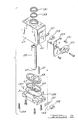
- Figure 3 is an exploded perspective view showing the preferred embodiment pin part locator
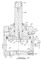
- Figure 4 is a cross sectional view, taken along line 4-4 of Figure 6, showing the preferred embodiment pin part locator
- Figure 5 is a cross sectional view, taken along line 5-5 of Figure 4, showing the preferred embodiment pin part locator disposed in a retracted position;
- Figure 6 is a cross sectional view, like that of Figure 5, showing the preferred embodiment pin part locator disposed in an advanced position;
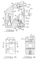
- Figure 7 is a fragmentary cross sectional view, taken along line 7-7 of Figure 4, showing the preferred embodiment pin part locator disposed in a retracted position;
- Figure 8 is a side elevational view showing a body employed with the preferred embodiment pin part locator
- Figure 9 is a cross sectional view, taken along line 9-9 of Figure 8, showing the body of the preferred embodiment pin part locator;
- Figure 10 is a side elevational view showing an end cap employed with the preferred embodiment pin part locator
- Figure 11 is a cross sectional view, taken along line 11-11 of Figure 10, showing the end cap of the preferred embodiment pin part locator;
- Figure 12 is a perspective view showing an off-center pin employed with the preferred embodiment pin part locator
- Figure 13 is a side elevational view showing the off-center pin of the preferred embodiment pin part locator.
- Figure 14 is a perspective view showing a seal employed with the preferred embodiment pin part locator.
- Pin part locator 21 includes a housing 23, a piston rod 25 and a part locator pin 27.
- Housing 23 further consists of a body 29 and an end cap 31.
- Body 29 is attached to a bracket 33 secured to a work table, manufacturing plant floor or robot. Multiple bolts secure bracket 33 to holes 35 and dowels serve to orient and prevent rotation of bracket 33 relative to holes 37.
- the rectangular body configuration allows for mounting of pin part locator 21 along any of the external body surfaces such as 39, 41, 43, 45 or the like.
- Piston rod 25 can be retracted and extended in order to protrude through a pair of openings 41 in multiple sheet metal panels or workpieces 43 and 45.
- Locator pin 27 is secured to a distal end of the piston rod by way of roll pins 47 or the like.
- body 29 includes an internal fluid chamber 51, a longitudinally elongated bore 53 and fluid ports 55 and 57.
- a piston 59 is movably located within fluid chamber 51 and piston rod 25 is movably positioned in bore 53.
- Piston 59 has a pair of opposed and generally flat faces 61 and 63 which are acted upon by the fluid pressure flowing from either port 55 or port 57.
- Piston 59 further has an oval peripheral shape which is sealed against the oval shaped internal wall of body 29 defining fluid chamber 51.
- a pair of V-shaped seals 65 are employed.
- a cap screw 67 centrally fastens piston 59 to piston rod 25. Furthermore, a circular-cylindrically shaped finger 69 is machined as an integral part of piston rod 25. Finger 69 protrudes from a proximal end of piston rod 25 and engages in a corresponding circular hole 71 of piston 59. Finger 69 is transversely offset from a longitudinal centerline 73 of piston 59 and piston rod 25. Thus, finger 69 and fastener 67 act to significantly deter rotation between piston rod 25 and piston 59. Additionally, the oval shape of piston 59 and the internal body wall defining fluid chamber 51 serve to significantly deter rotation between piston 59 and body 29.
- Off-center pin 81 is also attached to piston 59. This can best be observed in Figures 4, 7, 12 and 13. Off-center pin 81 has a threaded central segment 83 bordered by a pair of generally cylindrical segments 85 and 87. Frusto-conical leading end segments 89 and 91 are also provided. A pair of opposed wrench receiving flats 93 are employed on one of the cylindrical segments 87. Threaded segment 83 is secured within an internally threaded passage of piston 59. A Locktite brand adhesive is then used to further secure off-center pin 81 to piston 59. Cylindrical segments 85 and 87 project from the opposing faces of piston 59 and are oriented with an elongated centerline generally parallel to longitudinal piston centerline 73, but transversely offset therefrom.
- Segment 87 is receivable within an elongated hole 101 of body 29 when piston 59 is located in its advanced position, as shown in Figure 6.
- This engagement of off-center pin 81 with hole 101 serves the multiple functions of ensuring the accurate positioning of the workpiece locator relative to the body while also actuating a proximity switch sensor 103.
- retracted positioning of piston 59 causes off-center pin 81 to enter an opposite hole 105 in end cap 31. This also serves to actuate a second proximity switch sensor 105.
- FIGS. 7-11 illustrate the switch pocket configurations.
- a switch pocket 111 is machined within body 29 in an elongated direction generally perpendicular to piston centerline 73.
- Switch pocket 111 has a generally rectangular shape with rounded edges.
- a rounded opening 113 is also drilled through and past switch pocket 111 to intersect hole 101. This allows communication between switch pocket 111 and fluid chamber 51.
- Proximity switch 103 entirely fits within pocket 111 such that it is completely disposed below the adjacent nominal exterior surface of body 29.
- a molded rubber proximity head seal 121 with a generally oval peripheral shape, is located in an undercut area of switch pocket 111.
- proximity switch 103 is sealed within switch pocket 111 to prevent fluid from flowing therepast.
- Proximity switch can preferably be obtained from the Turck Inc.
- a similar switch pocket 123 and seal 125 arrangement is provided on end plate 31 for retaining proximity switch 105 and for interfacing with the corresponding segment of off-center pin 81.
- a dc or ac status controller switch block 127 which can also be obtained from Turck Inc., is bolted to a generally flat, cold rolled sheet metal plate 129 which, in turn, is fastened to the corresponding external surface of body 29 by screws 131.
- Status controller switch block 127 contains display lights and the appropriate input/output electrical connectors.
- a depressed channel 141 is machined in body 29 and end cap 31. This can be observed in Figures 3 and 10. These channels provide for passage of wires 143 to connect proximity switches 103 and 105 with status controller switch 127 (see Figure 7).
- Plate 129 also serves to completely cover and protect proximity switches 103 and 105 as well as wires 143 in channels 141.
- a wiper ring 151 and cup seal 153 act in combination with body 29 to provide an enlarged multiple point seat to accurately contact against and position piston rod 25.
- An O-ring 155 also is used to seal end cap 31 to body 29.
- a pair of roll pins 157 and four screws 159 secure end cap 31 to body 29.
- Off-center pin 81 is made of 4150 heat treated steel, piston rod 25 is machined from 6150 chrome-plated steel, while piston 59, end cap 31 and body 29 are all machined from 6061-T651 aluminum stock.
- the body is further hard coated to provide a hard and durable bearing, so as to eliminate the need for additional inserted bearings.
- the pin part locator of the present invention achieves enhanced precision of the piston rod and attached workpiece interface, relative to the desired centerline and housing by way of the offset finger, off-center pin and oval shaped piston.
- the internal mounting of the proximity switches further enhances compactness of the pin part locator thereby achieving easy packaging and mounting on a busy assembly line and also close spacing of the actuator portion of the locator, such as the piston, relative to the workpiece interfacing portion.
- the compact design may be machined to interface with other existing pin part locators by simply increasing the body size to suit the mounting area needed.
- the compact design can offer a flange mount, front face mount, side mount and center key mount.
- the stroke may vary by changing only the rod length, the body length and switch cover; all other components remain standard.
- the workpiece interface may be a gripper arm or cam actuated clamp coupled to the piston rod.
- the body may alternately have a cylindrical shape. While pneumatic fluid is preferred, hydraulic fluid can be employed. Additionally, other piston location sensors can be used in place of proximity switches. It is also envisioned that the finger may project from the piston for engaging in an aperture located in the piston rod. While various materials, shapes and manufacturing processes have been disclosed, it will be appreciated that others can be also employed. It is intended by the following claims to cover these and any other departures from the disclosed embodiments which fall within the true spirit of this invention.
Landscapes
- Engineering & Computer Science (AREA)
- Physics & Mathematics (AREA)
- Fluid Mechanics (AREA)
- Mechanical Engineering (AREA)
- General Engineering & Computer Science (AREA)
- Actuator (AREA)
- Fluid-Damping Devices (AREA)
Applications Claiming Priority (2)
| Application Number | Priority Date | Filing Date | Title |
|---|---|---|---|
| US521273 | 2000-03-08 | ||
| US09/521,273 US6502880B1 (en) | 2000-03-08 | 2000-03-08 | Pin part locator |
Publications (2)
| Publication Number | Publication Date |
|---|---|
| EP1132628A2 true EP1132628A2 (fr) | 2001-09-12 |
| EP1132628A3 EP1132628A3 (fr) | 2003-12-10 |
Family
ID=24076085
Family Applications (1)
| Application Number | Title | Priority Date | Filing Date |
|---|---|---|---|
| EP01302143A Withdrawn EP1132628A3 (fr) | 2000-03-08 | 2001-03-08 | Dispositif de positionnement de pièces grâce à une broche de centrage |
Country Status (2)
| Country | Link |
|---|---|
| US (1) | US6502880B1 (fr) |
| EP (1) | EP1132628A3 (fr) |
Cited By (3)
| Publication number | Priority date | Publication date | Assignee | Title |
|---|---|---|---|---|
| EP1462210A3 (fr) * | 2003-03-28 | 2007-05-30 | UNIVER S.p.A. | Dispositif de centrage avec élément de raclage |
| FR2895038A1 (fr) * | 2005-12-21 | 2007-06-22 | Univ Paris Curie | Systeme hydraulique. |
| IT202300009690A1 (it) | 2023-05-15 | 2024-11-15 | Pneumax S P A | Unita’ di centraggio con gruppo antirotazione |
Families Citing this family (17)
| Publication number | Priority date | Publication date | Assignee | Title |
|---|---|---|---|---|
| ATE311962T1 (de) * | 2000-03-15 | 2005-12-15 | Schunk Gmbh & Co Kg | Parallelgreifer |
| US6931980B1 (en) * | 2003-03-21 | 2005-08-23 | Zaytran, Inc. | Pneumatic device with cushioning mechanism |
| US7490532B2 (en) * | 2003-06-02 | 2009-02-17 | Norgren Automotive, Inc. | Rotatably adjustable apparatus for locating a workpiece |
| US20050035516A1 (en) * | 2003-08-14 | 2005-02-17 | Sawdon Edwin G. | Sealed pin locator clamp |
| US6902159B2 (en) * | 2003-08-21 | 2005-06-07 | Btm Corporation | Sealed pin locating and clamping apparatus |
| US7029000B2 (en) * | 2004-09-07 | 2006-04-18 | Btm Corporation | Sealed locking pin locator clamp |
| US7370856B2 (en) * | 2005-10-04 | 2008-05-13 | Btm Corporation | Rotating head pin clamp |
| US20080035113A1 (en) * | 2006-08-08 | 2008-02-14 | Thomas Friedrich | Rotary motor and a method for its manufacture |
| JP4929495B2 (ja) * | 2006-12-06 | 2012-05-09 | Smc株式会社 | ダンパ固定構造 |
| JP4737454B2 (ja) * | 2006-12-06 | 2011-08-03 | Smc株式会社 | 流体圧シリンダに用いられる止め輪 |
| JP4737453B2 (ja) * | 2006-12-06 | 2011-08-03 | Smc株式会社 | 流体圧シリンダ |
| US8459626B2 (en) | 2010-05-28 | 2013-06-11 | Btm Corporation | Pin clamp |
| CN102371587B (zh) * | 2010-08-09 | 2014-03-05 | 深圳富泰宏精密工业有限公司 | 定位夹取装置 |
| US20130111728A1 (en) * | 2011-11-09 | 2013-05-09 | Ford Global Technologies, Llc | Component fastening location system |
| US9156510B2 (en) | 2012-10-17 | 2015-10-13 | Btm Company Llc | Clamp mounting system |
| JP6410342B2 (ja) * | 2014-06-04 | 2018-10-24 | パスカルエンジニアリング株式会社 | 流体圧シリンダ及びクランプ装置 |
| DE102015218063A1 (de) * | 2015-09-21 | 2017-03-23 | Schunk Gmbh & Co. Kg Spann- Und Greiftechnik | Automationskomponente oder Spannvorrichtung mit einem Kolben |
Family Cites Families (31)
| Publication number | Priority date | Publication date | Assignee | Title |
|---|---|---|---|---|
| US2349253A (en) * | 1943-01-30 | 1944-05-23 | James M Edmund | Packing arrangement |
| FR1150962A (fr) * | 1956-05-24 | 1958-01-22 | Guillot Pelletier Fils & Jouff | Dispositif d'amortissement de fin de course pour vérin pneumatique |
| US3414693A (en) * | 1966-04-29 | 1968-12-03 | Tomkins Johnson Co | Cylinder head limit switch assembly |
| DK121336B (da) * | 1969-12-03 | 1971-10-04 | Islef & Hagen As | Arbejdscylinder med positionsgiver. |
| US3661053A (en) * | 1970-12-04 | 1972-05-09 | Parker Hannifin Corp | Reversing switch actuator for fluid motor |
| US3759146A (en) * | 1972-04-07 | 1973-09-18 | Timesavers Inc | Belt tensioner for wide belt sanding machines |
| DE2353168A1 (de) * | 1973-10-24 | 1975-04-30 | Gulde Regelarmaturen Kg | Pneumatischer antrieb |
| DE2519251A1 (de) * | 1975-04-30 | 1976-11-11 | Reinhold Pilzecker | Arbeitsgeraet, bestehend aus kolbenstange und zylinder |
| GB1471796A (en) * | 1975-05-30 | 1977-04-27 | Wack | Actuator fur electric welding |
| US4119017A (en) * | 1977-03-23 | 1978-10-10 | Phd, Inc. | Non-rotatable fluid power cylinder |
| US4206455A (en) * | 1978-06-09 | 1980-06-03 | Midland-Ross Corporation | Piston overtravel indicator |
| US4432130A (en) * | 1981-07-20 | 1984-02-21 | Lear Siegler, Inc. | Six station broaching machine |
| US4555979A (en) * | 1984-08-06 | 1985-12-03 | Robert Cetnarowski | Fluid-powered multiple pistonrod lift unit |
| DE8505017U1 (de) * | 1985-02-22 | 1985-05-15 | Festo KG, 7300 Esslingen | Hydraulischer oder pneumatischer arbeitszylinder |
| CA1289346C (fr) | 1986-02-27 | 1991-09-24 | Takeo Yoshiji | Systeme d'installation de pieces sur un element en cours de travail |
| DE3637068A1 (de) * | 1986-04-08 | 1987-12-23 | Samson Ag | Pneumatische antriebsvorrichtung fuer stellgeraete oder dergleichen |
| US4756229A (en) * | 1986-09-25 | 1988-07-12 | United Technologies Corporation | Digital motor feedback for a position actuator |
| CH674058A5 (fr) * | 1986-10-22 | 1990-04-30 | Festo Kg | |
| US5118088A (en) * | 1990-04-30 | 1992-06-02 | Btm Corporation | Power clamp |
| US5171001A (en) | 1987-05-27 | 1992-12-15 | Btm Corporation | Sealed power clamp |
| DE3870876D1 (de) * | 1988-08-18 | 1992-06-11 | Festo Kg | Linear-antriebseinrichtung. |
| JPH0341208U (fr) * | 1989-08-31 | 1991-04-19 | ||
| US5201838A (en) * | 1989-09-05 | 1993-04-13 | Philippe Roudaut | Position indicator for a piston controlled robot part |
| US5190334A (en) | 1991-03-11 | 1993-03-02 | Btm Corporation | Powered clamp with parallel jaws |
| DE4122481C2 (de) * | 1991-07-06 | 1995-08-31 | Kuhnke Gmbh Kg H | Kolben-Zylinder-Anordnung |
| US5165670A (en) | 1991-10-16 | 1992-11-24 | Btm Corporation | Retracting power clamp |
| US5308132A (en) * | 1992-10-05 | 1994-05-03 | Motorola, Inc. | Circuit assembly device for programmably controlling placement force and method thereto |
| DE19616441C1 (de) | 1996-04-25 | 1997-06-26 | Tuenkers Maschinenbau Gmbh | Kniehebelspannvorrichtung für den Karosseriebau |
| US5871250A (en) | 1997-03-31 | 1999-02-16 | Btm Corporation | Sealed straight line gripper |
| JP3150078B2 (ja) * | 1997-05-30 | 2001-03-26 | エスエムシー株式会社 | 溝カバー付き流体圧シリンダ |
| US6186567B1 (en) * | 1998-07-02 | 2001-02-13 | John Blick | Automatic clamping and placement holder |
-
2000
- 2000-03-08 US US09/521,273 patent/US6502880B1/en not_active Expired - Fee Related
-
2001
- 2001-03-08 EP EP01302143A patent/EP1132628A3/fr not_active Withdrawn
Cited By (6)
| Publication number | Priority date | Publication date | Assignee | Title |
|---|---|---|---|---|
| EP1462210A3 (fr) * | 2003-03-28 | 2007-05-30 | UNIVER S.p.A. | Dispositif de centrage avec élément de raclage |
| FR2895038A1 (fr) * | 2005-12-21 | 2007-06-22 | Univ Paris Curie | Systeme hydraulique. |
| WO2007074282A3 (fr) * | 2005-12-21 | 2007-08-16 | Univ Paris Curie | Presse hydraulique |
| US8127661B2 (en) | 2005-12-21 | 2012-03-06 | Universite Pierre Et Marie Curie | Hydraulic system |
| IT202300009690A1 (it) | 2023-05-15 | 2024-11-15 | Pneumax S P A | Unita’ di centraggio con gruppo antirotazione |
| DE112024001640T5 (de) | 2023-05-15 | 2026-03-12 | Pneumax S.P.A. | Zentriereinheit mit anti-rotationsgruppe |
Also Published As
| Publication number | Publication date |
|---|---|
| EP1132628A3 (fr) | 2003-12-10 |
| US6502880B1 (en) | 2003-01-07 |
Similar Documents
| Publication | Publication Date | Title |
|---|---|---|
| US6502880B1 (en) | Pin part locator | |
| US6908077B2 (en) | Clamp with swinging and linear motion | |
| US6059277A (en) | Retracting power clamp | |
| US6378855B1 (en) | Locking pin clamp | |
| US5871250A (en) | Sealed straight line gripper | |
| US6612557B2 (en) | Adjustable stroke clamp | |
| US20110291341A1 (en) | Pin clamp | |
| EP0771614B1 (fr) | Dispositif de serrage motorisé | |
| US6722842B1 (en) | End arm manipulator | |
| US6902159B2 (en) | Sealed pin locating and clamping apparatus | |
| US5215295A (en) | Enclosed rotatable head power clamp | |
| US6877730B2 (en) | Powered clamp | |
| US6322118B2 (en) | Jaw tips and jaw tip assemblies for parts grippers | |
| US7370856B2 (en) | Rotating head pin clamp | |
| KR890004048B1 (ko) | 슬라이드 실린더 | |
| US20050035516A1 (en) | Sealed pin locator clamp | |
| US4752094A (en) | Robot gripper or hand device | |
| EP0595168B1 (fr) | Pince de robot équipée d'un outil de mesure | |
| US7021687B2 (en) | Clamp assembly | |
| EP1636499B1 (fr) | Appareil pour positionner une piece a usiner par une course a reglage lineaire | |
| EP1031733A2 (fr) | Aménagement pour la fixation d'un vérin sur une base | |
| US11446726B2 (en) | Metal fastening die assembly | |
| EP0904901A1 (fr) | Dispositif de cible de positionement ajustable | |
| US7490532B2 (en) | Rotatably adjustable apparatus for locating a workpiece | |
| JP2574028Y2 (ja) | 着座及び把持確認装置 |
Legal Events
| Date | Code | Title | Description |
|---|---|---|---|
| PUAI | Public reference made under article 153(3) epc to a published international application that has entered the european phase |
Free format text: ORIGINAL CODE: 0009012 |
|
| AK | Designated contracting states |
Kind code of ref document: A2 Designated state(s): AT BE CH CY DE DK ES FI FR GB GR IE IT LI LU MC NL PT SE TR |
|
| AX | Request for extension of the european patent |
Free format text: AL;LT;LV;MK;RO;SI |
|
| PUAL | Search report despatched |
Free format text: ORIGINAL CODE: 0009013 |
|
| AK | Designated contracting states |
Kind code of ref document: A3 Designated state(s): AT BE CH CY DE DK ES FI FR GB GR IE IT LI LU MC NL PT SE TR |
|
| AX | Request for extension of the european patent |
Extension state: AL LT LV MK RO SI |
|
| RIC1 | Information provided on ipc code assigned before grant |
Ipc: 7F 15B 15/28 B Ipc: 7F 15B 15/08 A |
|
| AKX | Designation fees paid | ||
| REG | Reference to a national code |
Ref country code: DE Ref legal event code: 8566 |
|
| STAA | Information on the status of an ep patent application or granted ep patent |
Free format text: STATUS: THE APPLICATION IS DEEMED TO BE WITHDRAWN |
|
| 18D | Application deemed to be withdrawn |
Effective date: 20040612 |