EP1132629A2 - Zylinder und Positionsgeber - Google Patents
Zylinder und Positionsgeber Download PDFInfo
- Publication number
- EP1132629A2 EP1132629A2 EP01101767A EP01101767A EP1132629A2 EP 1132629 A2 EP1132629 A2 EP 1132629A2 EP 01101767 A EP01101767 A EP 01101767A EP 01101767 A EP01101767 A EP 01101767A EP 1132629 A2 EP1132629 A2 EP 1132629A2
- Authority
- EP
- European Patent Office
- Prior art keywords
- casing
- cylinder
- position detecting
- detecting sensor
- piston
- Prior art date
- Legal status (The legal status is an assumption and is not a legal conclusion. Google has not performed a legal analysis and makes no representation as to the accuracy of the status listed.)
- Granted
Links
Images











Classifications
-
- F—MECHANICAL ENGINEERING; LIGHTING; HEATING; WEAPONS; BLASTING
- F16—ENGINEERING ELEMENTS AND UNITS; GENERAL MEASURES FOR PRODUCING AND MAINTAINING EFFECTIVE FUNCTIONING OF MACHINES OR INSTALLATIONS; THERMAL INSULATION IN GENERAL
- F16J—PISTONS; CYLINDERS; SEALINGS
- F16J10/00—Engine or like cylinders; Features of hollow, e.g. cylindrical, bodies in general
-
- F—MECHANICAL ENGINEERING; LIGHTING; HEATING; WEAPONS; BLASTING
- F15—FLUID-PRESSURE ACTUATORS; HYDRAULICS OR PNEUMATICS IN GENERAL
- F15B—SYSTEMS ACTING BY MEANS OF FLUIDS IN GENERAL; FLUID-PRESSURE ACTUATORS, e.g. SERVOMOTORS; DETAILS OF FLUID-PRESSURE SYSTEMS, NOT OTHERWISE PROVIDED FOR
- F15B15/00—Fluid-actuated devices for displacing a member from one position to another; Gearing associated therewith
- F15B15/08—Characterised by the construction of the motor unit
- F15B15/14—Characterised by the construction of the motor unit of the straight-cylinder type
- F15B15/1423—Component parts; Constructional details
- F15B15/1438—Cylinder to end cap assemblies
-
- F—MECHANICAL ENGINEERING; LIGHTING; HEATING; WEAPONS; BLASTING
- F15—FLUID-PRESSURE ACTUATORS; HYDRAULICS OR PNEUMATICS IN GENERAL
- F15B—SYSTEMS ACTING BY MEANS OF FLUIDS IN GENERAL; FLUID-PRESSURE ACTUATORS, e.g. SERVOMOTORS; DETAILS OF FLUID-PRESSURE SYSTEMS, NOT OTHERWISE PROVIDED FOR
- F15B15/00—Fluid-actuated devices for displacing a member from one position to another; Gearing associated therewith
- F15B15/08—Characterised by the construction of the motor unit
- F15B15/14—Characterised by the construction of the motor unit of the straight-cylinder type
- F15B15/1423—Component parts; Constructional details
- F15B15/1428—Cylinders
-
- F—MECHANICAL ENGINEERING; LIGHTING; HEATING; WEAPONS; BLASTING
- F15—FLUID-PRESSURE ACTUATORS; HYDRAULICS OR PNEUMATICS IN GENERAL
- F15B—SYSTEMS ACTING BY MEANS OF FLUIDS IN GENERAL; FLUID-PRESSURE ACTUATORS, e.g. SERVOMOTORS; DETAILS OF FLUID-PRESSURE SYSTEMS, NOT OTHERWISE PROVIDED FOR
- F15B15/00—Fluid-actuated devices for displacing a member from one position to another; Gearing associated therewith
- F15B15/20—Other details, e.g. assembly with regulating devices
- F15B15/28—Means for indicating the position, e.g. end of stroke
- F15B15/2807—Position switches, i.e. means for sensing of discrete positions only, e.g. limit switches
-
- F—MECHANICAL ENGINEERING; LIGHTING; HEATING; WEAPONS; BLASTING
- F15—FLUID-PRESSURE ACTUATORS; HYDRAULICS OR PNEUMATICS IN GENERAL
- F15B—SYSTEMS ACTING BY MEANS OF FLUIDS IN GENERAL; FLUID-PRESSURE ACTUATORS, e.g. SERVOMOTORS; DETAILS OF FLUID-PRESSURE SYSTEMS, NOT OTHERWISE PROVIDED FOR
- F15B15/00—Fluid-actuated devices for displacing a member from one position to another; Gearing associated therewith
- F15B15/20—Other details, e.g. assembly with regulating devices
- F15B15/28—Means for indicating the position, e.g. end of stroke
- F15B15/2892—Means for indicating the position, e.g. end of stroke characterised by the attachment means
-
- F—MECHANICAL ENGINEERING; LIGHTING; HEATING; WEAPONS; BLASTING
- F16—ENGINEERING ELEMENTS AND UNITS; GENERAL MEASURES FOR PRODUCING AND MAINTAINING EFFECTIVE FUNCTIONING OF MACHINES OR INSTALLATIONS; THERMAL INSULATION IN GENERAL
- F16J—PISTONS; CYLINDERS; SEALINGS
- F16J10/00—Engine or like cylinders; Features of hollow, e.g. cylindrical, bodies in general
- F16J10/02—Cylinders designed to receive moving pistons or plungers
Definitions
- the present invention relates to a cylinder and a position detecting sensor, which makes it possible to prevent a liquid from being trapped on an outer surface of the cylinder thereby to avoid a sanitary problem.
- a hydraulic cylinder has heretofore been used as drive means for transferring and positioning workpieces or for driving various industrial machines.
- the hydraulic cylinder is provided with a cylinder tube and accessories including a switch attached to the cylinder tube, so as to meet various needs of a user, for example, so as to reduce the size and carry out various functions such as option setting. As a result, the hydraulic cylinder has a complicated contour.
- the complicated structure of the cylinder is liable to trap a liquid in the irregular surface such as a groove in the cylinder tube or a ridge or a rail for mounting a switch, after a rinsing or sterilizing operation with water or the like essential for the food processing machine.
- the residence of the liquid or the like in the irregular surface will result in multiplication of various germs.
- a switch which is attached to the hydraulic cylinder for detecting the position of a reciprocating piston has the same sanitary problem.
- the conventional switch (or the position detecting sensor) is desirably set at an arbitrary position on its stroke, for the usability of the hydraulic cylinder.
- the size of the switch has been reduced according as the size reduction of the hydraulic cylinder.
- the hydraulic cylinder body can be easily grooved thanks to the development in technique for molding an extruding member or the like.
- One method adopted for mounting the switch position adjusting mechanism is to mount the switch on the rail or groove formed on the hydraulic cylinder body by means of screws for enabling the size reduction and simple position adjustment.
- Another conventional method is to fix the switch on the hydraulic cylinder body by winding a band directly around the outer periphery of a cylinder tube.
- some switches attached to the cylinder tube are equipped with a detecting position adjusting mechanism capable of displacing the position of the piston to be detected.
- the conventional switch has a larger switch body since the detecting position adjusting mechanism is provided. Therefore, in the conventional switch, it is difficult to reduce its size and weight.
- a general object of the invention is to provide a cylinder comprising a cylinder tube having the outer periphery formed of outwardly (convexly) curved surfaces expect upright surfaces and having chamfered portions so as to prevent a liquid from being trapped on the outer surface thereby to avoid sanitary problems.
- a main object of the invention is to provide a position detecting sensor comprising a body having the outer periphery formed of curved portions curved convexly outward, and chamfered portions so as to prevent a liquid from being trapped on the outer surface thereby to avoid sanitary problems.
- Another object of the invention is to provide a position detecting sensor which makes it possible to provide a detection position adjusting mechanism without enlarging a sensor body so as to reduce the size and weight thereof.
- Still another object of the invention is to provide a cylinder which can reliably block invasion of a liquid or the like from the outside through a joint portion between a cylinder tube and a cover member.
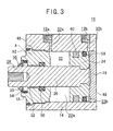
- the cylinder designated by reference numeral 10, comprises a substantially cylindrical cylinder tube 14 having a pair of pressurized fluid inlet/outlet ports 12a and 12b spaced at a predetermined distance, a head cover 16 fixed on one end of the cylinder tube 14, and a rod cover 18 fitted in a threaded hole on the other end of the cylinder tube 14.
- this cylinder tube 14 there are four mounting holes 20a to 20d extending in the axial direction.
- the cylinder 10 can be conveniently mounted on a wall surface or the like either by fastening unillustrated screw members in threaded portions of mounting holes 20a to 20d or by fastening unillustrated bolts in the mounting holes 20a to 20d.
- the cylinder 10 further includes a piston 24 displaceable along a cylinder chamber 22 defined in the cylinder tube 14 by the head cover 16 and the rod cover 18, a piston rod 26 attached to the piston 24 at its one end and exposed to the outside at its other end, and a scraper 30 mounted in the annular recess of the rod cover 18.
- the scraper 30 has a bore 28 fore receiving the outer circumferential surface of the piston rod 26.
- the pair of pressurized fluid inlet/outlet ports 12a and 12b communicate with the cylinder chamber 22 via passages 32a and 32b, respectively.
- the outer circumferential surfaces of the cylinder tube 14 include an upper surface 34 having the pair of pressurized fluid inlet/outlet ports 12a and 12b, a pair of slope surfaces 36a and 36b sloping down at a predetermined angle from the upper surface 34, a pair of opposite side surfaces 38a and 38b extending from the slope surfaces 36a and 36b, and a bottom surface 40 extending from the pair of side surfaces 38a and 38b.
- first chamfered portions 42 each having a predetermined radius of curvature.
- second chambered portions 44 each having a predetermined radius of curvature.
- third chamfered portions 46 each having a predetermined radius of curvature.
- each of the upper surface 34, the pair of slope surfaces 36a and 36b, the pair of side surfaces 38a and 38b and the bottom surface 40, which compose the outer periphery of the cylinder tube 14, comprises an outwardly (convexly) curved surface having a predetermined radius of curvature.
- the cylinder tube 14 Since all the outer circumferential surfaces of the cylinder tube 14 are formed of outwardly (convexly) curved surfaces and the first to third chamfered portions 42, 44 and 46, and the other side surfaces of the cylinder tube 14 are formed of upright surfaces (substantially vertical surfaces) 48, the cylinder tube 14 is contoured to allow the liquid on the outer surfaces of the cylinder tube 14 to naturally fall down in drops.
- the head cover 16 is caulked in the hole of the cylinder tube 14 so that it may function as a metal seal to keep the cylinder chamber 22 gas-tight and to prevent the invasion of the liquid or the like from the outside.
- a rod packing 50 is fitted through an annular groove.
- the rod packing 50 seals the outer circumferential surface of the piston rod 26 to keep the cylinder chamber 22 gas-tight and liquid-tight.
- a cylindrical bushing 52 is mounted in an annular recess formed in the inner circumferential surface of the rod cover 18, and a scraper 30 having a metallic member 54 embedded in a rubbery material is mounted in an annular recess formed in an end portion of the rod cover 18.
- An annular chamber 56 is formed between the scraper 30 and the rod cover 18. The annular chamber 56 functions as an oil sump to trap the lubricant on the outer circumferential surface of the piston rod 26.
- a piston packing 58 is fitted through an annular groove.
- the piston packing 58 is held in sliding contact with the inner wall surface of the cylinder chamber 22 to divide the cylinder chamber 22 into cylinder chambers 22a and 22b.
- a ring magnet 60 is mounted in the outer circumferential surface of the piston 24 in the outer circumferential surface of the piston 24 in the outer circumferential surface of the piston 24, a ring magnet 60 is mounted in the outer circumferential surface of the piston 24, a ring magnet 60 is mounted in the outer circumferential surface of the piston 24, a ring magnet 60 is mounted. The ring magnet 60 is disposed near the piston packing 58.
- annular sealing member 62 is disposed at an axial end of a joint between the cylinder tube 14 and the rod cover 18.
- the annular sealing member 62 is formed of a flexible material such as rubber. As shown in FIG. 4, the sealing member 62 is mounted such that it is partially clamped in a narrow spacing between an annular ridge 64 formed on the rod cover 18 and the inner circumferential surface 66 of the cylinder tube 14.
- the annular sealing member 62 formed to have a substantially uniform thickness in the circumferential direction is provided in advance with a squeeze which is clamped between the annular ridge 64 formed on the outer circumferential surface of the rod cover 18 and the inner circumferential surface 66 of the cylinder tube 14. Therefore, it is possible to prevent the liquid or the like from entering the joint between the cylinder tube 14 and the rod cover 18 from the outside thanks to the reliable sealing function of a clamped portion 68 of the sealing member 62. Accordingly, the entry of the liquid into the cylinder tube 14 is prevented.
- a pair of threaded holes 70 for mounting a position detecting sensor 100 are formed.
- FIGS. 6 to 11 the position detecting sensor 100 according to a first embodiment of the invention is shown in FIGS. 6 to 11.
- the position detecting sensor 100 includes a casing 102 made of a material such as an aluminum alloy, stainless steel or a synthetic resin and formed into a generally elliptical shape, and a resin member 106 made of a resin material such as an epoxy resin and fitted in a recess 104 of the casing 102 (see FIGS. 9 and 10).
- a substrate is buried.
- the substrate 110 is arranged with a detecting element 108.
- the substrate 110 is electrically connected to an end of a lead wire 112 which is exposed to the outside of the casing 102.
- the detecting element 108 is a non-contact type element such as a Hall element or a magnetic-resistance element.
- a pair of mounting holes 114a and 114b are formed.
- the mounting holes 114a and 114b extend at a predetermined spacing.
- screw members 116 having hexagonal heads are inserted.
- packings 118 for blocking the invasion of the liquid or the like into the mounting holes 114a and 114b are interposed.
- a gasket 120 is mounted on the bottom surface of the casing 102.
- the gasket 120 is made of a generally elliptical ring member extending along the peripheral edge of the casing 102. With this gasket 120, it is possible to prevent the entry of the liquid or the like into the clearance between the mounting surface of the cylinder 10 and the bottom surface of the casing 102.
- This casing 102 comprises an outwardly (convexly) curved upper surface 122 having a predetermined radius of curvature (e.g., R of about 200 mm), an elliptical side surface 124 extending from the upper surface 122, and a chamfered portion 126 having a predetermined radius of curvature (e.g., R of 3.5 mm) formed at the boundary portion between the upper surface 122 and the side surface 124.
- a predetermined radius of curvature e.g., R of about 200 mm
- a chamfered portion 126 having a predetermined radius of curvature (e.g., R of 3.5 mm) formed at the boundary portion between the upper surface 122 and the side surface 124.
- a bottom surface 128 of the casing 102 is curved to have a predetermined radius of curvature (e.g., R of about 200 mm) corresponding to the side surface 38b of the cylinder 10.
- the gasket 120 is attached to the bottom surface 128 of the casing 102.
- the bottom surface 128 of the casing 102 functions as a surface to be mounted on the side surface of the cylinder 10.
- the cylinder 10 and the position detecting sensor 100 according to the embodiment of the invention are basically constructed as described hereinabove, and their actions and effects will be described below.
- the screw members 116 are inserted into the mounting holes 114a and 114b of the position detecting sensor 100, and an end of the screw members 116 are screwed into the threaded holes 70 of the cylinder 10, so that the position detecting sensor 100 is mounted on the side surface 38b of the cylinder 10 (see FIG. 11).
- a pressurized fluid e.g., air
- a pressurized fluid e.g., air
- the pressurized fluid thus supplied into the pressurized fluid inlet/outlet port 12a is introduced via the passage 32a into the cylinder chamber 22a to push the piston 24 toward the cylinder chamber 22b.
- the magnetic field of the magnet 60 mounted on the piston 24 is detected by the detecting element 108 of the position detecting sensor 100, so that the position detecting sensor 100 outputs a detection signal to an external device such as an unillustrated controller through the lead wire 112 connected to the substrate 110.
- the cylinder 10 and the position detecting sensor 100 attached to the cylinder 10 according to the embodiment are assembled with an unillustrated food processing machine or the like for performing washing operations.
- the entire outer periphery of the cylinder tube 14 is formed of the outwardly (convexly) curved surfaces and the first to third chamfered portions 42, 44 and 46.
- the casing 102 of the position detecting sensor 100 is formed of the curved upper surface 122 having the predetermined radius of curvature, the elliptical side surface 124 extending from the upper surface 122, and the chamfered portion 126 having the predetermined radius of curvature formed at the boundary portion between the upper surface 122 and the side surface 124.
- the liquid on the outer peripheries of the cylinder tube 14 and the position detecting sensor 100 easily falls down in drops. Accordingly, it is possible to prevent the liquid from being trapped in the outer peripheries of the cylinder tube 14 and the position detecting sensor 100.
- the cylinder 10 and the position detecting sensor 100 according to the embodiment are contoured such that the liquid is hardly trapped in their outer surfaces but naturally falls in drops. Accordingly, it is possible to avoid sanitary problems such as breeding of various germs.
- the annular sealing member 62 is advantageously utilized.
- the annular sealing member 62 has the squeeze clamped between the annular ridge 64 formed on the outer circumferential surface of the rod cover 18 and the inner circumferential surface 66 of the cylinder tube 14.
- an O-ring 76 having a circular cross section is fitted in a joint portion between a cylinder tube 72 and a rod cover 74.
- the liquid or the like invades through the joint portion between the cylinder tube 72 and the rod cover 74 up to the portion where the O-ring is fitted. As a result, unwanted germs are bred by the liquid or the like.
- the O-ring 76 fitted in the cylinder 78 according to the comparison example of FIG. 5 has only the function to block the air in the cylinder chamber from leaking to the outside, and the liquid having flown through the joint portion between the cylinder tube 72 and the rod cover 74 is allowed to invade into the portion where the O-ring 76 is fitted thereby to facilitate the breeding of the various germs.
- the sealing is reliably effected by the clamped portion 68 of the sealing member 62. Therefore, the invasion of the liquid or the like, as might otherwise occur from the outside into the cylinder tube 14 through the joint portion between the cylinder tube 14 and the rod cover 18, can be reliably blocked. As a result, the various germs can be prevented from being bred by the liquid or the like, thereby making it possible to avoid the sanitary problems.
- the resin member 106 is formed by embedding the substrate 110 having the detecting element 108 in the resin material or the like.
- the resin member 106 is formed integrally with the casing 102 in the recess 104.
- the screw members 116 By inserting the screw members 116 into the mounting holes 114a and 114b formed in the casing 102, the detecting element 108, the substrate 110, the casing 102 and so on can be integrally fitted to the cylinder 10.
- no clearance for allowing the invasion of the liquid or the like is formed in the casing 102 so that no respiratory action occurs due to the change of temperature. Therefore, it is possible to prevent the breeding of fungi or bacteria, as might otherwise be caused by the moisture or the like in the casing 102.
- the position detecting sensor 100 is advantageous in that its size and weight can be reduced and in that the surface area of the casing 102 can be decreased to suppress the total amount of the liquid which resides on the casing 102.
- the threaded holes 70 formed in the side surface 38b of the cylinder 10 may be closed with closure means such as unillustrated bolts having seal washers.
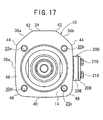
- FIGS. 12 to 17 a position detecting sensor 200 according to a second embodiment is shown in FIGS. 12 to 17.
- the same components as those of the position detecting sensor 100 shown in FIG. 6 are designated by the common reference numerals, and the detailed description thereof will be omitted.
- the position detecting sensor 200 comprises a casing 206 of a rectangular cross section having a pair of generally parallel slots 202a and 202b and a pair of mounting holes 204a and 204b, a cover member 208 to be fitted over the casing 206, and hexagonal bolts 210 for fixing the cover member 208 on the casing 206. Between the cover member 208 and the casing 206, a gasket 212 for blocking the invasion of the liquid or the like into the inside is interposed.
- a substrate 216 is positioned in a closed chamber 214 defined by the casing 206 and the cover member 208.
- An unillustrated detecting element is mounted on the substrate 216.
- the aforementioned lead wire 112 is electrically connected with the substrate 216.
- the position detecting sensor 200 can be mounted on the cylinder 10 (see FIG. 17) by inserting mounting screws 218 individually into the slots 202a and 202b of the casing 206 and by fastening the mounting screws 218 into the threaded holes 70 formed in one side of the cylinder 10.
- the function to lock the position detecting sensor 200 can be achieved by using the pair of mounting screws 218.
- the upper surface 220 of the cover member 208 and the bottom surface 222 of the casing 206 are convexly curve to have a predetermined radius of curvature (e.g., R of about 200 mm), as shown in FIGS. 14 and 15.
- the peripheral portions 224 formed in a generally rectangular shape to extend from the upper surface of the cover member 208 are chamfered.
- the four corner portions of the cover member 208 and the four corner portions of the casing 206 are chamfered.
- the position of the position detecting sensor 200 can be adjusted by removing the cover member 208 and displacing the casing 206 in the axial direction along the slots 202a and 202b engaging with the mounting screws 218.
- the position detecting sensor 200 can be easily mounted by forming the pair of threaded holes in the mounting surface or the side surface of the cylinder and by fastening the pair of mounting screws 218 in the pair of threaded holes.
- the mounting surface on the cylinder side can be formed in a simple shape while retaining the position adjusting function.
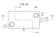
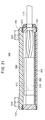
- FIGS. 18 to 21 a position detecting sensor 300 according to a third embodiment is shown in FIGS. 18 to 21.
- the same components as those of the position detecting sensor 200 according to the second embodiment, as shown in FIG. 12, are designated by the common reference numerals, and their detailed description will be omitted.
- the position detecting sensor 300 comprises a casing 304 of a rectangular section having a rail 302 arranged to extend at the central portion in an axial direction, and a cover member 306 to be fitted over the casing 304.
- a rail 302 arranged to extend at the central portion in an axial direction
- a cover member 306 to be fitted over the casing 304.
- an axial recess 308 is formed in the axial direction, in which a cylindrical sensor portion 310 is retained in a predetermined position through a screw member 312.
- the sensor portion 310 is provided with an unillustrated detecting element which is molded of a resin material or the like.
- the casing 206 is made movable along the slots.
- the position detecting sensor 300 according to the third embodiment is characterized in that the casing 304 is fixed on the cylinder 10 by the mounting screws 218 and in that the position to be detected can be adjusted by displacing the sensor portion 310 along the recess of the rail 302.
- the sensor portion 310 is shared to provide advantages that a compatibility is established to correspond to various cylinders 10 of different shapes and standards, and that the sensor portion can be easily replaced by a new one for maintenance.
- the upper surface 220 of the cover member 306 and the bottom surface 222 of the casing 304 are convexly curved outward to have a predetermined radius of curvature (e.g., R of about 200 mm), in a similar manner to the second embodiment.
- the peripheral portions, as formed in a generally rectangular shape to extend from the upper surface of the cover member 306, are chamfered at a portion 224, and the cover member 306 and the casing 304 are likewise chamfered at the four corner portions.
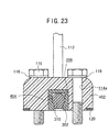
- FIGS. 22 to 24 a position detecting sensor 400 according to a fourth embodiment is shown in FIGS. 22 to 24.
- the position detecting sensor 400 according to the fourth embodiment is characterized, as shown in FIGS. 23 and 24, in that a groove portion 404 which extends in the axial direction is formed in the bottom surface of an integral casing 402, and in that the rail 302 and the sensor portion 310 are fitted in the groove portion 404.
- the casing is divided into the casing 304 and the cover member 306, and the hexagonal bolts 210 are provided for fitting the cover member 306 on the casing 304 and the mounting screws 218 for mounting the position detecting sensor 300 itself in the threaded holes of the cylinder 10.
- the position detecting sensor 400 according to the fourth embodiment is different in that the integral casing 402 is formed to have a generally elliptical section similar to that of the position detecting sensor 100 according to the first embodiment, and in that the rail 302 and the sensor portion 310, as used in the position detecting sensor 300 according to the third embodiment, are integrally provided in the groove portion 404 which is formed in the bottom surface of the casing 402.
- the sensor portion 310 can be displaced along the recess 308 of the rail 302.
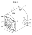
- FIGS. 25 to 31 a position detecting sensor 500 according to a fifth embodiment of the invention is shown in FIGS. 25 to 31.
- the magnet 60 fitted on the outer circumference of the piston 24 is magnetized (or radially magnetized) such that the magnet 60 has the magnetic poles in the radial directions of the piston 24 that an S-pole (or N-pole) may be established on the inner circumferential surface of the ring body whereas an N-pole (or S-pole) may be established on the outer circumferential surface of the ring body (see FIGS. 29 and 31).
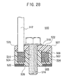
- This position detecting sensor 500 comprises, as shown in FIG. 28, a casing 502 formed of a material such as an aluminum alloy, stainless steel or a synthetic resin into a generally disc shape, a resin member 506 made of a resin material such as an epoxy resin and fitted in an annular recess 504 of the casing 502, and a generally disc-shaped cover member 507 fitted on the upper surface of the casing 502 to close the recess 504.
- an unillustrated substrate is buried.
- the substrate has a detecting element 508 arranged thereon and is electrically connected to one end portion of a lead wire 512 exposed to the outside of the casing 502.
- the detecting element 508 is suitably exemplified by one of the non-contact type such as the Hall element or the magnetic-resistance element.
- a mounting hole 514 is extended therethrough, into which a screw member 516 having a hexagonal head is inserted.
- the screw member 516 By loosening the screw member 516 from the side surface of the cylinder 10, the casing 502 and the cover member 507 is circumferentially rotatable on the axis of the screw member 516.
- a packing 518 is sandwiched for blocking the invasion of the liquid or the like into the mounting hole 514.
- a gasket 520 made of a circular ring member is fitted for blocking the invasion of the liquid or the like into the clearance between the mounting surface of the cylinder 10 and the bottom surface of the casing 502.
- the position detecting sensor 500 comprises, as shown in FIG. 28, an upper surface 522 given a predetermined radius of curvature (e.g., R of about 200 mm) and curved convexly outward, a circumferential side surface 524 extending from the upper surface 522, and a chamfered portion 526 formed at the boundary between the upper surface 522 and the side surface 524 and given a predetermined radius of curvature (e.g., R of 1.0 mm).
- a predetermined radius of curvature e.g., R of about 200 mm
- a chamfered portion 526 formed at the boundary between the upper surface 522 and the side surface 524 and given a predetermined radius of curvature (e.g., R of 1.0 mm).
- the upper surface 522 may be suitably formed of a spherical surface having a predetermined radius of curvature, substituting the aforementioned convexly curved surface.
- the position detecting sensor 500 according to the fifth embodiment is basically constructed as described hereinbefore, and its actions and effects will be described in the following.
- the position detecting sensor 500 is fitted in the side surface 38b of the cylinder 10 (as should be referred to FIG. 25) by inserting the screw member 516 into the mounting hole 514 of the position detecting sensor 500 and by fastening one end portion of the screw member 516 into the unillustrated threaded hole of the cylinder 10.
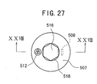
- the position detecting sensor 500 is arranged such that the detecting element 508 is positioned on a radially output extension B through the (not shown) center of the magnet 60, and the rotary position of the detecting element 508 at this time is set to 0 degree.
- the position detecting sensor 500 is turned on its center O (or on the axis of the screw member 516) in a predetermined direction to adjust the detecting position of the detecting element 508 to a predetermined position.
- the maximum adjustment of the position detecting sensor 500 can be set to a double distance of a radius C from the center O of the position detecting sensor 500 to the detecting element 508 by turning the position detecting sensor 500 circumferentially by about 180 degrees from the rotary position of 0 degrees to the rotary position of 180 degrees.
- the pressurized fluid (such as air) is fed from the unillustrated pressurized fluid supply source to the one pressurized fluid inlet/outlet port 12a.
- the pressurized fluid thus fed to the one pressurized fluid inlet/outlet port 12a is introduced via the passage 32a into the one cylinder chamber 22a to push the piston 24 toward the other cylinder chamber 22b.
- the magnetic field of the magnet 60, fitted on the piston 24, is detected by the detecting element 508 of the position detecting sensor 500 so that the position detecting sensor 500 outputs a detection signal to an external device such as an unillustrated controller through the lead wire 512 connected with the substrate.
- the piston 24 is displaced to return to an initial position by switching the feed of the pressurized fluid from the one pressurized fluid inlet/outlet port 12a to the other pressurized fluid inlet/outlet port 12b under the switching action of an unillustrated directional control valve.
- the piston 24, as fitted in the cylinder tube 14, can be reciprocated along the cylinder chamber 22.
- the detecting element 508 can rotate circumferentially on the center O of the position detecting sensor 500 so that the casing 502 need not be enlarged according to the slide amount of the detecting element 508. The size and weight can be reduced even when a detecting position adjusting mechanism is provided.
- an effect is obtained that the magnetic field to be generated from the magnet 60 can be reliably detected even when the rotary angle of the detecting element 508 changes, by magnetizing the magnetism of the magnet 60 in the radial directions of the piston 24 (i.e., in a direction generally perpendicular to the axis of the piston rod 26), as shown in FIG. 31, and by setting the easily sensing direction of the detecting element 508 in the radial directions, as shown in FIG. 31.
- FIG. 32 a comparison example is shown in which the magnetic poles of a magnet 600 are magnetized along the axial direction of the piston rod 26 so that a detecting element 602 can be displaced generally in parallel (i.e., in the direction of arrows D) with the axis of the piston rod 26.
- This comparison example is troubled in that when the magnetic force is excessively strong (or when the detecting sensitivity of the detecting element 602 is excessively high), the detecting element 602 detects the peak values of a multiplicity of individual magnetic forces so that it malfunctions to be turned ON several times.
- the position detecting sensor 500 according to the fifth embodiment is advantageous in that it is enabled to detect the peak of the magnetic force practically as one peak while being not influenced by the strength of the magnetic force or the detection sensitivity of the detecting element 508, by disposing the detecting element 508 rotatably in the circumferential direction on the center O of the position detecting sensor 500 and by magnetizing the magnetic poles of the magnet 60 in the radial directions to generate the magnetic field along the radial directions, as shown in FIG. 31.
- the position detecting sensor 500 according to the fifth embodiment can widen the range for setting the magnetic force and the detection sensitivity.
- the magnetic force of the magnet 600 is detected by the position detecting sensor 500 according to the fifth embodiment
- this detection of the magnetic force may be difficult depending upon the rotary position of the position detecting sensor 500.
- the magnetic force can be detected when the detecting element 508 is at the rotary positions of 0 degrees or 180 degrees, but is hardly detected when the detecting element 508 is at the rotary position of about 90 degrees.
- the substrate having the detecting element 508 is molded of the resin material or the like to form the resin member 506, which is integrally covered with the casing 502 and the cover member 507.
- the detecting element 508, the unillustrated substrate, the cover member 507, the casing 502 and so on can be integrally fitted on the cylinder 10 by the screw member 516 to be inserted into the mounting hole 514 formed in the casing 502 and the cover member 507.
- the position detecting sensor 500 according to the fifth embodiment is advantageous in that the surface areas of the casing 502 and the cover member 507 can be decreased to suppress the total residence sum of the liquid.
- the screw hole, as formed in the side surface 38b of the cylinder 10, may be closed by closing means such as a bolt having an unillustrated sealing washer.
- the invention has been described on the cases in which the position detecting sensors 100, 200, 300, 400 and 500 according to the first to fifth embodiments are attached to the cylinder 10.
- the invention should not be limited thereto, but the position detecting sensors can naturally be applied to various hydraulic devices or electric actuators such as the unillustrated linear actuator.
Landscapes
- Engineering & Computer Science (AREA)
- General Engineering & Computer Science (AREA)
- Mechanical Engineering (AREA)
- Physics & Mathematics (AREA)
- Fluid Mechanics (AREA)
- Chemical & Material Sciences (AREA)
- Combustion & Propulsion (AREA)
- Actuator (AREA)
- Optical Measuring Cells (AREA)
Priority Applications (1)
| Application Number | Priority Date | Filing Date | Title |
|---|---|---|---|
| EP05012069A EP1607637B8 (de) | 2000-03-01 | 2001-01-26 | Zylinder |
Applications Claiming Priority (4)
| Application Number | Priority Date | Filing Date | Title |
|---|---|---|---|
| JP2000056440 | 2000-03-01 | ||
| JP2000056437A JP3644865B2 (ja) | 2000-03-01 | 2000-03-01 | シリンダ |
| JP2000056440A JP4392570B2 (ja) | 2000-03-01 | 2000-03-01 | 位置検出センサ |
| JP2000056437 | 2000-03-01 |
Related Child Applications (1)
| Application Number | Title | Priority Date | Filing Date |
|---|---|---|---|
| EP05012069A Division EP1607637B8 (de) | 2000-03-01 | 2001-01-26 | Zylinder |
Publications (4)
| Publication Number | Publication Date |
|---|---|
| EP1132629A2 true EP1132629A2 (de) | 2001-09-12 |
| EP1132629A3 EP1132629A3 (de) | 2004-07-21 |
| EP1132629B1 EP1132629B1 (de) | 2006-05-31 |
| EP1132629B8 EP1132629B8 (de) | 2006-08-02 |
Family
ID=26586564
Family Applications (2)
| Application Number | Title | Priority Date | Filing Date |
|---|---|---|---|
| EP05012069A Expired - Lifetime EP1607637B8 (de) | 2000-03-01 | 2001-01-26 | Zylinder |
| EP01101767A Expired - Lifetime EP1132629B8 (de) | 2000-03-01 | 2001-01-26 | Zylinder |
Family Applications Before (1)
| Application Number | Title | Priority Date | Filing Date |
|---|---|---|---|
| EP05012069A Expired - Lifetime EP1607637B8 (de) | 2000-03-01 | 2001-01-26 | Zylinder |
Country Status (6)
| Country | Link |
|---|---|
| US (1) | US6520065B2 (de) |
| EP (2) | EP1607637B8 (de) |
| KR (1) | KR100426794B1 (de) |
| CN (1) | CN1201103C (de) |
| DE (2) | DE60120009T2 (de) |
| TW (1) | TW459107B (de) |
Cited By (2)
| Publication number | Priority date | Publication date | Assignee | Title |
|---|---|---|---|---|
| DE10242266A1 (de) * | 2002-09-12 | 2004-03-25 | Continental Teves Ag & Co. Ohg | In einen Hauptzylinder integrierter Signalgeber Magneto-Widerstand |
| US7021192B2 (en) | 2003-03-07 | 2006-04-04 | Smc Kabushiki Kaisha | Cylinder apparatus |
Families Citing this family (22)
| Publication number | Priority date | Publication date | Assignee | Title |
|---|---|---|---|---|
| US20040052664A1 (en) * | 2001-01-05 | 2004-03-18 | Atsuji Saito | High-pressure fuel feed pump |
| EP1895170B1 (de) * | 2005-06-21 | 2016-03-09 | ASA Electronics Industry Co., Ltd. | Zylindersteuerungseinheit |
| JP2007040316A (ja) * | 2005-07-29 | 2007-02-15 | Smc Corp | 環状磁石およびそれを用いた流体圧シリンダ |
| KR200448808Y1 (ko) * | 2007-12-18 | 2010-05-24 | 파인텍 씨오., 엘티디. | 변환기용 보호 케이싱 |
| JP4529093B2 (ja) * | 2007-12-19 | 2010-08-25 | Smc株式会社 | 流体圧シリンダのピストン位置検出装置 |
| US20110011257A1 (en) * | 2009-07-16 | 2011-01-20 | Parker Hannifin Corporation | Electro-hydraulic actuator having end cap with split bushing |
| DE112010003599B4 (de) * | 2009-09-09 | 2024-01-25 | Smc Corp. | Luftzylinder |
| KR101378045B1 (ko) | 2009-09-11 | 2014-03-27 | 에스엠시 가부시키가이샤 | 에어 실린더 |
| JP5417588B2 (ja) * | 2009-11-13 | 2014-02-19 | Smc株式会社 | アクチュエータ |
| JP4941849B2 (ja) * | 2009-11-30 | 2012-05-30 | Smc株式会社 | 位置検出装置付き流体圧シリンダ |
| CN101893087A (zh) * | 2010-07-14 | 2010-11-24 | 大连工业大学 | 叠片组合式矩形油缸 |
| ES2684688T3 (es) | 2012-03-01 | 2018-10-04 | Special Springs S.R.L. | Actuador de cilindro de gas con dispositivo de seguridad de sobrerrecorrido |
| JP6028994B2 (ja) * | 2012-06-18 | 2016-11-24 | Smc株式会社 | 流体圧シリンダ |
| CN102943785B (zh) * | 2012-11-27 | 2015-11-11 | 湖南特力液压有限公司 | 活塞缸及其安装方法 |
| US9821881B2 (en) * | 2013-10-01 | 2017-11-21 | Shimano Inc. | Bicycle hydraulic operating device |
| JP6614490B2 (ja) * | 2015-12-01 | 2019-12-04 | Smc株式会社 | 位置検出センサ |
| JP6614489B2 (ja) * | 2015-12-01 | 2019-12-04 | Smc株式会社 | 位置検出センサ |
| DE102017108855C5 (de) * | 2017-04-26 | 2023-09-07 | Asm Automation Sensorik Messtechnik Gmbh | Sensor-Einheit sowie Arbeitszylinder-Einheit mit einer Sensor-Einheit |
| CN111341606B (zh) * | 2018-12-18 | 2021-12-31 | 天津平高智能电气有限公司 | 一种断路器及其操动机构 |
| CN112066937B (zh) * | 2020-09-04 | 2022-08-09 | 长治市鑫磁科技有限公司 | 一种钕铁硼磁圈倒角检测机构 |
| US11261886B1 (en) * | 2021-06-14 | 2022-03-01 | King Yuan Fu Packaging Co., Ltd. | Pneumatic cylinder and mechanical apparatus using the same |
| CN115199613B (zh) * | 2022-09-16 | 2022-12-02 | 江阴市洪腾机械有限公司 | 液压缸安全监测装置 |
Family Cites Families (16)
| Publication number | Priority date | Publication date | Assignee | Title |
|---|---|---|---|---|
| US2533531A (en) * | 1945-07-24 | 1950-12-12 | William T Stephens | Cylinder assembly |
| FR2239605A1 (en) * | 1973-07-31 | 1975-02-28 | Thenaud Rene | Method of assembling hydraulic or pneumatic jacks - involves deforming cylinder over head and base with sealing rings |
| DE3546865C2 (de) * | 1985-03-01 | 1997-05-28 | Festo Kg | Kolben-Zylinder-Anordnung |
| JPS634470U (de) * | 1986-06-27 | 1988-01-12 | ||
| JPH0410413Y2 (de) * | 1986-10-15 | 1992-03-16 | ||
| JPS63122902A (ja) * | 1986-11-13 | 1988-05-26 | Ckd Controls Ltd | 移動体の位置確認装置 |
| DE3801076A1 (de) * | 1988-01-17 | 1989-07-27 | Friedrich Freimuth | Befestigungs- und dichtungsring |
| US4924758A (en) * | 1988-08-01 | 1990-05-15 | Yuda Lawrence F | Compact fluid operated apparatus and method |
| JPH03125904A (ja) * | 1989-10-11 | 1991-05-29 | Matsuura Denshi Device:Kk | 位置警報・調節装置 |
| SE463684B (sv) * | 1989-12-22 | 1991-01-07 | Mecman Ab | Haallaranordning foer kolvlaegesavkaennare |
| JP2524400Y2 (ja) * | 1990-05-08 | 1997-01-29 | シーケーディ 株式会社 | ピストン位置検出器の取り付け構造 |
| DE29501243U1 (de) * | 1995-01-27 | 1995-04-20 | Festo Kg, 73734 Esslingen | Arbeitszylinder |
| US5680808A (en) * | 1996-05-09 | 1997-10-28 | Ingersoll-Rand Company | Fluid cylinder and method of assembly |
| DE29701155U1 (de) * | 1997-01-24 | 1997-03-13 | Festo Kg, 73734 Esslingen | Fluidbetätigter Arbeitszylinder |
| DE29816156U1 (de) * | 1998-09-09 | 1998-11-26 | Festo AG & Co, 73734 Esslingen | Linearantrieb |
| DE29910970U1 (de) * | 1999-06-23 | 1999-09-02 | Festo AG & Co, 73734 Esslingen | Fluidbetätigter Arbeitszylinder |
-
2001
- 2001-01-26 EP EP05012069A patent/EP1607637B8/de not_active Expired - Lifetime
- 2001-01-26 DE DE60120009T patent/DE60120009T2/de not_active Expired - Lifetime
- 2001-01-26 DE DE60133147T patent/DE60133147T2/de not_active Expired - Lifetime
- 2001-01-26 EP EP01101767A patent/EP1132629B8/de not_active Expired - Lifetime
- 2001-02-05 TW TW090102386A patent/TW459107B/zh not_active IP Right Cessation
- 2001-02-15 KR KR10-2001-0007540A patent/KR100426794B1/ko not_active Expired - Lifetime
- 2001-02-28 CN CNB011089342A patent/CN1201103C/zh not_active Expired - Lifetime
- 2001-03-01 US US09/795,348 patent/US6520065B2/en not_active Expired - Lifetime
Cited By (2)
| Publication number | Priority date | Publication date | Assignee | Title |
|---|---|---|---|---|
| DE10242266A1 (de) * | 2002-09-12 | 2004-03-25 | Continental Teves Ag & Co. Ohg | In einen Hauptzylinder integrierter Signalgeber Magneto-Widerstand |
| US7021192B2 (en) | 2003-03-07 | 2006-04-04 | Smc Kabushiki Kaisha | Cylinder apparatus |
Also Published As
| Publication number | Publication date |
|---|---|
| EP1132629B1 (de) | 2006-05-31 |
| TW459107B (en) | 2001-10-11 |
| CN1311405A (zh) | 2001-09-05 |
| DE60120009T2 (de) | 2007-01-11 |
| CN1201103C (zh) | 2005-05-11 |
| EP1132629B8 (de) | 2006-08-02 |
| EP1607637B8 (de) | 2008-06-18 |
| KR100426794B1 (ko) | 2004-04-14 |
| DE60120009D1 (de) | 2006-07-06 |
| DE60133147D1 (de) | 2008-04-17 |
| US6520065B2 (en) | 2003-02-18 |
| EP1607637A1 (de) | 2005-12-21 |
| EP1607637B1 (de) | 2008-03-05 |
| KR20010087187A (ko) | 2001-09-15 |
| DE60133147T2 (de) | 2009-02-19 |
| US20010018862A1 (en) | 2001-09-06 |
| EP1132629A3 (de) | 2004-07-21 |
Similar Documents
| Publication | Publication Date | Title |
|---|---|---|
| EP1132629B1 (de) | Zylinder und Positionsgeber | |
| US6571681B2 (en) | Attachment structure for position-detecting sensor | |
| EP1227250A2 (de) | Verbindungsstruktur eines Wegnehmers | |
| EP2327963A2 (de) | Flüssigkeitsdruckzylinder mit Positionsdetektor | |
| EP1069320B1 (de) | Vorgesteuertes Wegeventil mit Positionsermittlung | |
| US5926018A (en) | Proximity switch | |
| SE465683B (sv) | Kolvcylinderaggregat | |
| EP2614278A2 (de) | Ventil mit druckausgleich und einem membranen-enddichtungselement | |
| US5613421A (en) | Rodless cylinder | |
| US6637316B2 (en) | Pressure fluid cylinder with optional anti-rotation feature | |
| JPH07233802A (ja) | シリンダ | |
| JP4392570B2 (ja) | 位置検出センサ | |
| JP3644865B2 (ja) | シリンダ | |
| JP2001113428A (ja) | クランプシリンダ | |
| JP2001107914A (ja) | クランプシリンダ | |
| JPH102304A (ja) | 流体圧シリンダ | |
| JPH0532722Y2 (de) | ||
| JPH10331810A (ja) | 流体圧シリンダ装置 | |
| KR20090003543U (ko) | 실린더 위치검출수단을 구비한 유압실린더 | |
| JPH07332311A (ja) | ロッドレスシリンダー | |
| KR20090003542U (ko) | 실린더 위치검출수단을 구비한 유압실린더 |
Legal Events
| Date | Code | Title | Description |
|---|---|---|---|
| PUAI | Public reference made under article 153(3) epc to a published international application that has entered the european phase |
Free format text: ORIGINAL CODE: 0009012 |
|
| AK | Designated contracting states |
Kind code of ref document: A2 Designated state(s): AT BE CH CY DE DK ES FI FR GB GR IE IT LI LU MC NL PT SE TR |
|
| AX | Request for extension of the european patent |
Free format text: AL;LT;LV;MK;RO;SI |
|
| PUAL | Search report despatched |
Free format text: ORIGINAL CODE: 0009013 |
|
| AK | Designated contracting states |
Kind code of ref document: A3 Designated state(s): AT BE CH CY DE DK ES FI FR GB GR IE IT LI LU MC NL PT SE TR |
|
| AX | Request for extension of the european patent |
Extension state: AL LT LV MK RO SI |
|
| 17P | Request for examination filed |
Effective date: 20041020 |
|
| 17Q | First examination report despatched |
Effective date: 20041202 |
|
| AKX | Designation fees paid |
Designated state(s): DE SE |
|
| GRAP | Despatch of communication of intention to grant a patent |
Free format text: ORIGINAL CODE: EPIDOSNIGR1 |
|
| GRAS | Grant fee paid |
Free format text: ORIGINAL CODE: EPIDOSNIGR3 |
|
| GRAA | (expected) grant |
Free format text: ORIGINAL CODE: 0009210 |
|
| AK | Designated contracting states |
Kind code of ref document: B1 Designated state(s): DE SE |
|
| REF | Corresponds to: |
Ref document number: 60120009 Country of ref document: DE Date of ref document: 20060706 Kind code of ref document: P |
|
| RTI2 | Title (correction) |
Free format text: CYLINDER |
|
| REG | Reference to a national code |
Ref country code: SE Ref legal event code: TRGR |
|
| PLBE | No opposition filed within time limit |
Free format text: ORIGINAL CODE: 0009261 |
|
| STAA | Information on the status of an ep patent application or granted ep patent |
Free format text: STATUS: NO OPPOSITION FILED WITHIN TIME LIMIT |
|
| 26N | No opposition filed |
Effective date: 20070301 |
|
| PGFP | Annual fee paid to national office [announced via postgrant information from national office to epo] |
Ref country code: DE Payment date: 20200121 Year of fee payment: 20 Ref country code: SE Payment date: 20200121 Year of fee payment: 20 |
|
| REG | Reference to a national code |
Ref country code: DE Ref legal event code: R071 Ref document number: 60120009 Country of ref document: DE |
|
| REG | Reference to a national code |
Ref country code: SE Ref legal event code: EUG |