EP1132632A2 - Galet avec roulement à billes - Google Patents
Galet avec roulement à billes Download PDFInfo
- Publication number
- EP1132632A2 EP1132632A2 EP01100816A EP01100816A EP1132632A2 EP 1132632 A2 EP1132632 A2 EP 1132632A2 EP 01100816 A EP01100816 A EP 01100816A EP 01100816 A EP01100816 A EP 01100816A EP 1132632 A2 EP1132632 A2 EP 1132632A2
- Authority
- EP
- European Patent Office
- Prior art keywords
- hole
- ring
- closure element
- roller
- balls
- Prior art date
- Legal status (The legal status is an assumption and is not a legal conclusion. Google has not performed a legal analysis and makes no representation as to the accuracy of the status listed.)
- Withdrawn
Links
Images


Classifications
-
- F—MECHANICAL ENGINEERING; LIGHTING; HEATING; WEAPONS; BLASTING
- F16—ENGINEERING ELEMENTS AND UNITS; GENERAL MEASURES FOR PRODUCING AND MAINTAINING EFFECTIVE FUNCTIONING OF MACHINES OR INSTALLATIONS; THERMAL INSULATION IN GENERAL
- F16C—SHAFTS; FLEXIBLE SHAFTS; ELEMENTS OR CRANKSHAFT MECHANISMS; ROTARY BODIES OTHER THAN GEARING ELEMENTS; BEARINGS
- F16C13/00—Rolls, drums, discs, or the like; Bearings or mountings therefor
- F16C13/006—Guiding rollers, wheels or the like, formed by or on the outer element of a single bearing or bearing unit, e.g. two adjacent bearings, whose ratio of length to diameter is generally less than one
-
- F—MECHANICAL ENGINEERING; LIGHTING; HEATING; WEAPONS; BLASTING
- F16—ENGINEERING ELEMENTS AND UNITS; GENERAL MEASURES FOR PRODUCING AND MAINTAINING EFFECTIVE FUNCTIONING OF MACHINES OR INSTALLATIONS; THERMAL INSULATION IN GENERAL
- F16C—SHAFTS; FLEXIBLE SHAFTS; ELEMENTS OR CRANKSHAFT MECHANISMS; ROTARY BODIES OTHER THAN GEARING ELEMENTS; BEARINGS
- F16C43/00—Assembling bearings
- F16C43/04—Assembling rolling-contact bearings
- F16C43/06—Placing rolling bodies in cages or bearings
-
- F—MECHANICAL ENGINEERING; LIGHTING; HEATING; WEAPONS; BLASTING
- F16—ENGINEERING ELEMENTS AND UNITS; GENERAL MEASURES FOR PRODUCING AND MAINTAINING EFFECTIVE FUNCTIONING OF MACHINES OR INSTALLATIONS; THERMAL INSULATION IN GENERAL
- F16C—SHAFTS; FLEXIBLE SHAFTS; ELEMENTS OR CRANKSHAFT MECHANISMS; ROTARY BODIES OTHER THAN GEARING ELEMENTS; BEARINGS
- F16C2240/00—Specified values or numerical ranges of parameters; Relations between them
- F16C2240/40—Linear dimensions, e.g. length, radius, thickness, gap
- F16C2240/70—Diameters; Radii
- F16C2240/80—Pitch circle diameters [PCD]
- F16C2240/82—Degree of filling, i.e. sum of diameters of rolling elements in relation to PCD
- F16C2240/84—Degree of filling, i.e. sum of diameters of rolling elements in relation to PCD with full complement of balls or rollers, i.e. sum of clearances less than diameter of one rolling element
-
- F—MECHANICAL ENGINEERING; LIGHTING; HEATING; WEAPONS; BLASTING
- F16—ENGINEERING ELEMENTS AND UNITS; GENERAL MEASURES FOR PRODUCING AND MAINTAINING EFFECTIVE FUNCTIONING OF MACHINES OR INSTALLATIONS; THERMAL INSULATION IN GENERAL
- F16C—SHAFTS; FLEXIBLE SHAFTS; ELEMENTS OR CRANKSHAFT MECHANISMS; ROTARY BODIES OTHER THAN GEARING ELEMENTS; BEARINGS
- F16C33/00—Parts of bearings; Special methods for making bearings or parts thereof
- F16C33/30—Parts of ball or roller bearings
- F16C33/58—Raceways; Race rings
Definitions
- the present invention relates to a rolling-contact bearing and a ball roller for lift trucks in accordance with the precharacterising part of the independent claims, and a method for their connection to a support element.
- a ball roller means a particular radial type of rolling-contact ball bearing, in which the inner ring is fixed and secured to a support pin, whereas the outer ring is free to rotate.
- the outer ring has a strengthened structure to "rotate” on a flat or curved surface and withstand radial loads in the manner in which a wheel supports them.
- the outer ring acting as a "wheel”, rotates on balls.
- Rollers of the present definition cover a range of standard dimensions not exceeding 130 mm. in outer diameter, and are approved for use in the lift truck sector.
- the known filling method considerably influences the production time and cost of those radial ball bearings which adopt it, and is generally usable for bearings of greater dimensions than those of the ball rollers usually used in the vertical lifting guides of lift trucks.
- An object of the present invention is to provide a rolling-contact ball bearing or a roller in which the aforesaid drawbacks are overcome and, in particular, in which the operations necessary for loading the rolling bodies are simplified and accelerated, and which is able to withstand greater loads than conventional rollers.
- a roller according to the invention comprises an outer ring 1, and an inner ring 2 coaxial to the first, the opposing surfaces of the two rings each comprising an annular seat 1A, 2A functioning as a rolling track delimiting a toric annular space 4 in which the rolling bodies 3, which in the represented example are of ball type, roll.
- the rolling bodies 3 completely fill the space 4 between the two tracks and are inserted between the two tracks through a radial hole 5 ( Figure 4) in the inner ring 4, when the inner and outer rings are disposed one inside the other.
- the hole 5 is closed by an element 6.
- the space 8 ( Figure 2) between one ring and the other, lateral to the space 4, is advantageously closed by a circular gasket 7.
- the rings 1, 2 and the rolling bodies are substantially of conventional type and will therefore not be described in detail.
- the closure element 6 has a substantially cylindrical body and presents at that end 6A in contact with the balls 3 a recessed shape having a curvature equal to that of the seat or track 2A, so that when the closure element 6 has been inserted into the hole 5, that end 6A is adequately flush with the track 2A.
- the other end 6B of the closure element 6 has instead a cylindrical curvature greater than that of the inner wall 2B ( Figure 5) of the ring 2. That end 6B can also be flat.
- the closure element is dimensioned such that when its end 6A is flush with the track 2A of the inner ring 2, the other end 6B is flush with the cylindrical inner surface delimiting the cylindrical aperture 11 in the ring 2, and into it there can be inserted without interference the support element 10 ( Figures 9, 10), to which the inner ring 2 is secured. Because of its particular form, the closure element 6 is inserted into the hole 5 without being forced therein or being secured by pins or other members for securing it to the ring 2, and is retained in the hole by the action of the balls 3, which completely fill the space 4, and of the support element 10 secured to the inner ring 2.
- the closure element 6 is advantageously formed by moulding a plastic material, for example a polyamide or acetal resin or a suitable composite material, or from another material with similar characteristics, such as brass or aluminium.
- a plastic material for example a polyamide or acetal resin or a suitable composite material, or from another material with similar characteristics, such as brass or aluminium.
- the roller of the invention is rigidly secured to the support element 10, for example a pin engaging the inner ring 2, such that the radial loads F, F1, F2 acting on the roller are not transmitted onto the closure element 6, said loads being substantially supported by that part of the rings 1 and 2 not comprising the hole 5 and by those balls 3 not in contact with the closure element 6.
- a groove 12 is provided in the aperture 11 delimited by the inner ring 2.
- the roller of the invention can withstand even axial loads without any difficulty, because under axial load the balls 3 are without load at the moment in which they come into contact with said element 6, it being the other balls of the roller which support the axial load.
- the groove 12 provided in the inner ring 2 can also facilitate the positioning of this ring on the pin.
- this groove visible from the outside even when the pin 10 is inserted in the ring 2, clearly indicates where the closure element 6 is positioned.
- Figures 7, 8 show a first modification to the already described roller; this modification is substantially equal to the preceding solution but comprises two rolling tracks and consequently two holes for loading the balls and two closure elements (all those components in common which the preceding embodiment are indicated by the same numerals).
- rollers of Figures 1-10 can also be used as a radial rolling-contact bearing by taking account of the load arising during operation.
- the ball insertion hole can be provided either in the inner ring, as shown in Figures 1-10, or in the outer ring, as shown in Figures 11, 11A, 11B.
- the outer ring comprises a radial hole 5' closed by a plug 6' of the already described type.
- the plug is free to rotate so that it can correctly orientate itself during passage of the balls.
- the plug cannot however move axially.
- that end 6A which comes into contact with the rolling bodies has a recessed shape equal or similar to that of the rolling track 1A' of the holed ring whereas the other end 6B' of the closure element 6' has a convex curvature of radius less than the radius of that wall 1B' of the holed ring 1' in contact with the seat of the housing 21.
- the closure element 6' is dimensioned such that when it has been inserted in the hole 5' the ends (6A' and 6B') are flush with the rolling track 1A' and the wall 1B', so that the track 1A' is free of substantial discontinuities.
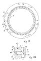
- FIGS 12, 12A show a rolling contact bearing in which the outer ring 14 is to be rigidly secured to a support element (not shown), for example by bolts engaging in threaded holes 15, and the inner ring 16 rotates on balls 17 which completely fill the space between the two rings.
- the outer ring comprises a radial hole 18 closed by a plug 19 of the already described type.
- the plug is free to rotate so that it can correctly orientate itself during passage of the balls.
- the plug cannot however move axially, and for this purpose there is provided in the outer ring a lateral through hole into which a pin 20 is inserted.
- the pin 20 also indicates the position of the plug 19 and enables the outer element 1 to be rigidly secured to the support element.
- the means for securing the fixed ring of the roller to the relative support element could be different from those described but conventional for the expert of the art.
- the ring presenting the ball insertion hole could comprise a reference element, visible from the outside even when the relative support element is associated with said ring.
- This reference element can for example be a notch provided along the outer faces of the ring, to indicate the exact position of said hole and said closure element.
- the ring presenting the hole into which the closure plug is inserted could also be rotatable; according to the invention, it is in fact necessary for the plug to be able to rotate within the hole in which it is housed and be locked to prevent axial movements which could cause it to escape from the ring into which it is inserted. Consequently, with reference for example to the bearing of Figures 11, 11A, 11B, the outer ring 1' could also rotate.
Landscapes
- Engineering & Computer Science (AREA)
- General Engineering & Computer Science (AREA)
- Mechanical Engineering (AREA)
- Rolling Contact Bearings (AREA)
- Mounting Of Bearings Or Others (AREA)
- Fuel-Injection Apparatus (AREA)
- Pinball Game Machines (AREA)
- Pulleys (AREA)
Applications Claiming Priority (2)
| Application Number | Priority Date | Filing Date | Title |
|---|---|---|---|
| IT2000MI000488A IT1317584B1 (it) | 2000-03-10 | 2000-03-10 | Rotella a sfere |
| ITMI200488 | 2000-03-10 |
Publications (2)
| Publication Number | Publication Date |
|---|---|
| EP1132632A2 true EP1132632A2 (fr) | 2001-09-12 |
| EP1132632A3 EP1132632A3 (fr) | 2003-01-02 |
Family
ID=11444413
Family Applications (1)
| Application Number | Title | Priority Date | Filing Date |
|---|---|---|---|
| EP01100816A Withdrawn EP1132632A3 (fr) | 2000-03-10 | 2001-01-15 | Galet avec roulement à billes |
Country Status (2)
| Country | Link |
|---|---|
| EP (1) | EP1132632A3 (fr) |
| IT (1) | IT1317584B1 (fr) |
Cited By (7)
| Publication number | Priority date | Publication date | Assignee | Title |
|---|---|---|---|---|
| WO2004104436A1 (fr) * | 2003-04-30 | 2004-12-02 | Volvo Construction Equipment Holding Sweden Ab | Element annulaire et dispositif d'entrainement comprenant ledit element |
| CN1299018C (zh) * | 2004-08-26 | 2007-02-07 | 常熟长城轴承有限公司 | 轴承 |
| EP3001058A1 (fr) * | 2014-09-29 | 2016-03-30 | Aktiebolaget SKF | Ensemble de bouchon, palier à roulement comprenant un tel ensemble et machine comprenant un tel palier |
| US10428874B2 (en) | 2014-12-19 | 2019-10-01 | Saint-Gobain Performance Plastics Pampus Gmbh | Sliding component and method of forming the same |
| CN115539504A (zh) * | 2022-09-16 | 2022-12-30 | 人本股份有限公司 | 一种圆柱滚子轴承 |
| WO2023140748A1 (fr) * | 2022-01-19 | 2023-07-27 | Gosiewski Damian | Dispositif de tamisage et de ségrégation de matières premières solides |
| CN116838716A (zh) * | 2023-05-06 | 2023-10-03 | 临清森信轴承制造有限公司 | 一种装卸方便使用灵活的滚动轴承 |
Family Cites Families (8)
| Publication number | Priority date | Publication date | Assignee | Title |
|---|---|---|---|---|
| GB197861A (en) * | 1922-07-04 | 1923-05-24 | George Trish | Improvements in ball bearings |
| US2624644A (en) * | 1947-07-31 | 1953-01-06 | Crane Co | Valve actuating mechanism |
| FR2222897A5 (fr) * | 1973-03-20 | 1974-10-18 | Rks | |
| FR2502714A1 (fr) * | 1981-03-25 | 1982-10-01 | Glaenzer Spicer Sa | Roulement a billes et son procede d'assemblage, et appareil de rectification d'un tel roulement |
| JP2511112B2 (ja) * | 1988-07-12 | 1996-06-26 | 日本トムソン株式会社 | 蓋付き旋回輪軸受の潤滑装置 |
| IT1227656B (it) * | 1988-12-01 | 1991-04-23 | Omet S R L L | Cuscinetto volvente |
| US5218764A (en) * | 1989-07-05 | 1993-06-15 | Nippon Thompson Co., Ltd. | Method of manufacturing a rotary bearing assembly having an insertion hole |
| GB2318840A (en) * | 1996-10-29 | 1998-05-06 | Torrington Co | Ball bearing |
-
2000
- 2000-03-10 IT IT2000MI000488A patent/IT1317584B1/it active
-
2001
- 2001-01-15 EP EP01100816A patent/EP1132632A3/fr not_active Withdrawn
Cited By (8)
| Publication number | Priority date | Publication date | Assignee | Title |
|---|---|---|---|---|
| WO2004104436A1 (fr) * | 2003-04-30 | 2004-12-02 | Volvo Construction Equipment Holding Sweden Ab | Element annulaire et dispositif d'entrainement comprenant ledit element |
| US7156769B2 (en) | 2003-04-30 | 2007-01-02 | Volvo Construction Equipment Holding Sweden Ab | Annular member and drive device comprising the annular member |
| CN1299018C (zh) * | 2004-08-26 | 2007-02-07 | 常熟长城轴承有限公司 | 轴承 |
| EP3001058A1 (fr) * | 2014-09-29 | 2016-03-30 | Aktiebolaget SKF | Ensemble de bouchon, palier à roulement comprenant un tel ensemble et machine comprenant un tel palier |
| US10428874B2 (en) | 2014-12-19 | 2019-10-01 | Saint-Gobain Performance Plastics Pampus Gmbh | Sliding component and method of forming the same |
| WO2023140748A1 (fr) * | 2022-01-19 | 2023-07-27 | Gosiewski Damian | Dispositif de tamisage et de ségrégation de matières premières solides |
| CN115539504A (zh) * | 2022-09-16 | 2022-12-30 | 人本股份有限公司 | 一种圆柱滚子轴承 |
| CN116838716A (zh) * | 2023-05-06 | 2023-10-03 | 临清森信轴承制造有限公司 | 一种装卸方便使用灵活的滚动轴承 |
Also Published As
| Publication number | Publication date |
|---|---|
| IT1317584B1 (it) | 2003-07-15 |
| ITMI20000488A1 (it) | 2001-09-10 |
| EP1132632A3 (fr) | 2003-01-02 |
Similar Documents
| Publication | Publication Date | Title |
|---|---|---|
| US7273141B2 (en) | One-way clutch integrated with a rolling bearing, and method of producing the same | |
| US4472006A (en) | Roller bearing with an improved cage | |
| US4475777A (en) | Split-ring roller bearing | |
| CN100532874C (zh) | 径向滚动轴承、特别是单列深沟球轴承 | |
| US4411479A (en) | Double row angular contact ball bearing with one-piece outer ring and one-piece inner ring | |
| EP1132632A2 (fr) | Galet avec roulement à billes | |
| US5102242A (en) | Roller bearing for supporting shafts with limited axial movement | |
| EP1875093B1 (fr) | Roulement etanche | |
| EP3779245B1 (fr) | Dispositif d'étanchéité | |
| JP2002013540A (ja) | 複列旋回軸受 | |
| US4138169A (en) | Two row rolling bearing assembly having single piece inner ring and two piece outer ring | |
| JPH0557449B2 (fr) | ||
| US5885009A (en) | Cage for cylindrical rolling elements | |
| CN106499734A (zh) | 用于滚动轴承单元的密封装置 | |
| US5237748A (en) | Method of making a bearing assembly | |
| GB2319309A (en) | Radial rolling bearing | |
| JPS60231015A (ja) | 自動調心ころがり軸受のシール装置 | |
| US3924908A (en) | Roller with inserted ball bearings | |
| US5913350A (en) | Door lock for a motor vehicle door formed integrally with the door hinge | |
| CN114198399A (zh) | 用于滚动轴承、尤其是大直径滚动轴承的保持架分段 | |
| GB2084666A (en) | Improvements in cylindrical roller bearings | |
| US4623268A (en) | Ball bearing | |
| US4236766A (en) | Roller having supporting body between outer tread body and inner bearing | |
| US3999817A (en) | Separator ring for retaining rollers in a thrust bearing | |
| JP3928922B2 (ja) | 玉軸受 |
Legal Events
| Date | Code | Title | Description |
|---|---|---|---|
| PUAI | Public reference made under article 153(3) epc to a published international application that has entered the european phase |
Free format text: ORIGINAL CODE: 0009012 |
|
| AK | Designated contracting states |
Kind code of ref document: A2 Designated state(s): AT BE CH CY DE DK ES FI FR GB GR IE IT LI LU MC NL PT SE TR |
|
| AX | Request for extension of the european patent |
Free format text: AL;LT;LV;MK;RO;SI |
|
| PUAL | Search report despatched |
Free format text: ORIGINAL CODE: 0009013 |
|
| AK | Designated contracting states |
Kind code of ref document: A3 Designated state(s): AT BE CH CY DE DK ES FI FR GB GR IE IT LI LU MC NL PT SE TR |
|
| AX | Request for extension of the european patent |
Free format text: AL;LT;LV;MK;RO;SI |
|
| RIC1 | Information provided on ipc code assigned before grant |
Free format text: 7F 16C 13/00 A, 7F 16C 33/58 B, 7F 16C 43/06 B, 7F 16C 33/64 B, 7F 16C 19/04 B |
|
| AKX | Designation fees paid | ||
| REG | Reference to a national code |
Ref country code: DE Ref legal event code: 8566 |
|
| STAA | Information on the status of an ep patent application or granted ep patent |
Free format text: STATUS: THE APPLICATION IS DEEMED TO BE WITHDRAWN |
|
| 18D | Application deemed to be withdrawn |
Effective date: 20030703 |