EP1132675A1 - Dichte Rohrverbindung mit geringer Einschränkung und Faltenbalg - Google Patents
Dichte Rohrverbindung mit geringer Einschränkung und Faltenbalg Download PDFInfo
- Publication number
- EP1132675A1 EP1132675A1 EP01104946A EP01104946A EP1132675A1 EP 1132675 A1 EP1132675 A1 EP 1132675A1 EP 01104946 A EP01104946 A EP 01104946A EP 01104946 A EP01104946 A EP 01104946A EP 1132675 A1 EP1132675 A1 EP 1132675A1
- Authority
- EP
- European Patent Office
- Prior art keywords
- tube
- hose
- male
- female
- bellows
- Prior art date
- Legal status (The legal status is an assumption and is not a legal conclusion. Google has not performed a legal analysis and makes no representation as to the accuracy of the status listed.)
- Withdrawn
Links
- 239000013536 elastomeric material Substances 0.000 claims 1
- 238000002485 combustion reaction Methods 0.000 abstract description 5
- 238000004519 manufacturing process Methods 0.000 description 2
- 238000012986 modification Methods 0.000 description 2
- 230000004048 modification Effects 0.000 description 2
- 239000000853 adhesive Substances 0.000 description 1
- 230000001070 adhesive effect Effects 0.000 description 1
- 238000000034 method Methods 0.000 description 1
- 238000004023 plastic welding Methods 0.000 description 1
- 238000003466 welding Methods 0.000 description 1
Images
Classifications
-
- F—MECHANICAL ENGINEERING; LIGHTING; HEATING; WEAPONS; BLASTING
- F16—ENGINEERING ELEMENTS AND UNITS; GENERAL MEASURES FOR PRODUCING AND MAINTAINING EFFECTIVE FUNCTIONING OF MACHINES OR INSTALLATIONS; THERMAL INSULATION IN GENERAL
- F16L—PIPES; JOINTS OR FITTINGS FOR PIPES; SUPPORTS FOR PIPES, CABLES OR PROTECTIVE TUBING; MEANS FOR THERMAL INSULATION IN GENERAL
- F16L27/00—Adjustable joints; Joints allowing movement
- F16L27/10—Adjustable joints; Joints allowing movement comprising a flexible connection only
- F16L27/107—Adjustable joints; Joints allowing movement comprising a flexible connection only the ends of the pipe being interconnected by a flexible sleeve
- F16L27/11—Adjustable joints; Joints allowing movement comprising a flexible connection only the ends of the pipe being interconnected by a flexible sleeve the sleeve having the form of a bellows with multiple corrugations
-
- F—MECHANICAL ENGINEERING; LIGHTING; HEATING; WEAPONS; BLASTING
- F16—ENGINEERING ELEMENTS AND UNITS; GENERAL MEASURES FOR PRODUCING AND MAINTAINING EFFECTIVE FUNCTIONING OF MACHINES OR INSTALLATIONS; THERMAL INSULATION IN GENERAL
- F16L—PIPES; JOINTS OR FITTINGS FOR PIPES; SUPPORTS FOR PIPES, CABLES OR PROTECTIVE TUBING; MEANS FOR THERMAL INSULATION IN GENERAL
- F16L31/00—Arrangements for connecting hoses to one another or to flexible sleeves
Definitions
- the present invention relates generally to a low restriction hose and seal assembly which allows for changes in duct length of a hose connecting an air cleaner to an engine.
- An air cleaner brings air into an internal combustion engine at the required temperature and velocity.
- a hose is commonly employed to connect the air cleaner to the engine. During operation, the engine may move up to one inch due to vibrations.
- the hose commonly includes a plurality of bellows which accommodate the movement of the engine. If the engine moves during operation, the bellows on the hose contract and expand, allowing for expansion of the hose and accommodating for engine movement.
- the present invention relates generally to a low restriction hose and seal assembly which allows for changes in duct length of a hose connecting an air cleaner to an engine.
- a hose assembly connects an air cleaner to an internal combustion engine.
- a male hose inserted within a female hose is slidably connected by an elastomeric seal with a plurality of bellows.
- the elastomeric seal is bonded around the circumference of the exterior surfaces of the female hose and the exterior surface of the male hose at bonding points.
- the bellows are between 3 and 5 millimeters in height.
- the seal is bonded around the circumference of the exterior surfaces by welding or adhesive.
- the male hose When the hose assembly is in the compressed state, the male hose is positioned within the female hose such that the internal end of the male hose substantially contacts a tapered end of the female hose.
- the movement of the engine and vibrations cause the female hose and the male hose to separate.
- the bellows of the flexible elastomeric seal separate, allowing for the expansion of the seal. This allows for the expansion of the hose to accommodate for engine movement.
- the present invention provides a low restriction hose and seal assembly which allows for changes in duct length of a hose connecting an air cleaner to an engine.
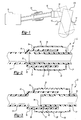
- Figure 1 illustrates an air intake and an engine.
- Figure 2 illustrates the low restriction hose and seal assembly of the present invention in the compressed state.
- Figure 3 illustrates the low restriction hose and seal assembly of the present invention in the extended state.
- FIG. 1 illustrates an air cleaner 10 attached to an internal combustion engine 100 connected by a hose assembly 22.
- the hose assembly 22 is connected to a throttle body 16, which is secured to an intake manifold 14 that attaches to the engine 10.
- the engine 100 will roll on mounts 12, requiring the hose assembly 22 to accommodate a change in hose length.
- the internal combustion engine 100 may move up to one inch or more due to vibrations and load.
- the air cleaner 10 is connected to the engine, the hose assembly 22 must be able to accommodate for movement of the engine.
- the polymeric hose assembly 22 as illustrated in Figures 2 and 3 includes a male hose 26 inserted within a female hose 24.
- the hoses 24, 26 are attached by a thin, flexible, elastomeric seal 28.
- the seal 28 is bonded around the circumference of the exterior surface 30 of the female hose 24 and around the circumference of the exterior surface 32 of the male hose 26 at bonding points 34.
- the seal 28 is bonded around the circumference of the exterior surfaces 30, 32 by appropriate plastic welding techniques.
- the seal 28 includes a plurality of bellows 36.
- the bellows 36 are between 3 and 5 millimeters in height, but are not limited to this height.
- the bellows 36 are formed in the seal 28 substantially between the bonding points 34.
- the hose assembly 22 in the compressed state is illustrated in Figure 2.
- an internal end 38 of the male hose 26 substantially contacts a tapered end 40 of the female hose 24.
- the male hose 26 is positioned within the female hose 24 such that the external surface 32 of the male hose 26 substantially contacts the internal surface 42 of the female hose 24.
- the elastomeric seal 28 contains bellows 36 which allow for expansion of the seal 28, the female hose 24 and the male hose 26 of the hose 22 can slidingly separate to accommodate for engine movement.
- the hose assembly 22 of the present invention can also be installed in an intake manifold 14 to act as the runners. By varying the runner length on an intake manifold 14, there are additional acoustic and flow tuning possibilities.
Landscapes
- Engineering & Computer Science (AREA)
- General Engineering & Computer Science (AREA)
- Mechanical Engineering (AREA)
- Rigid Pipes And Flexible Pipes (AREA)
- Joints Allowing Movement (AREA)
Applications Claiming Priority (2)
| Application Number | Priority Date | Filing Date | Title |
|---|---|---|---|
| US18773100P | 2000-03-08 | 2000-03-08 | |
| US187731P | 2000-03-08 |
Publications (1)
| Publication Number | Publication Date |
|---|---|
| EP1132675A1 true EP1132675A1 (de) | 2001-09-12 |
Family
ID=22690228
Family Applications (1)
| Application Number | Title | Priority Date | Filing Date |
|---|---|---|---|
| EP01104946A Withdrawn EP1132675A1 (de) | 2000-03-08 | 2001-02-28 | Dichte Rohrverbindung mit geringer Einschränkung und Faltenbalg |
Country Status (2)
| Country | Link |
|---|---|
| US (1) | US6390138B2 (de) |
| EP (1) | EP1132675A1 (de) |
Cited By (1)
| Publication number | Priority date | Publication date | Assignee | Title |
|---|---|---|---|---|
| GB2478513A (en) * | 2009-12-16 | 2011-09-14 | Eaton Fluid Power Gmbh | An expansion joint having relatively movable inner tubes and a flexible outer sleeve |
Families Citing this family (2)
| Publication number | Priority date | Publication date | Assignee | Title |
|---|---|---|---|---|
| JP3944183B2 (ja) * | 2004-04-01 | 2007-07-11 | 本田技研工業株式会社 | 車両の排気系支持構造 |
| WO2005109060A1 (en) * | 2004-05-11 | 2005-11-17 | Emtelle Uk Limited | Network of tubes for optical fibres |
Citations (6)
| Publication number | Priority date | Publication date | Assignee | Title |
|---|---|---|---|---|
| US4283078A (en) * | 1980-05-01 | 1981-08-11 | Ross Victor H | Flexible joint protector |
| US4350372A (en) * | 1980-01-21 | 1982-09-21 | Logsdon Duane D | Expansion coupling for large diameter plastic pipes |
| US5370427A (en) * | 1994-01-10 | 1994-12-06 | General Electric Company | Expansion joint for fluid piping with rotation prevention member |
| FR2745626A1 (fr) * | 1996-03-01 | 1997-09-05 | Peugeot | Dispositif de guidage d'un gaz s'ecoulant dans un conduit courbe a soufflet |
| EP0807749A2 (de) * | 1996-05-13 | 1997-11-19 | Scambia Industrial Developments Aktiengesellschaft | Abgasanlage für ein Kraftfahrzeug sowie Kraftfahrzeug |
| FR2755493A1 (fr) * | 1996-11-05 | 1998-05-07 | Inst Francais Du Petrole | Dispositif de raccordement etanche d'un boitier fixe coiffant l'extremite d'un element tubulaire sur lui-meme |
Family Cites Families (12)
| Publication number | Priority date | Publication date | Assignee | Title |
|---|---|---|---|---|
| US3369829A (en) * | 1965-10-15 | 1968-02-20 | William C.N. Hopkins | Flexible connector for fluid conduit systems |
| US3388931A (en) | 1967-03-31 | 1968-06-18 | Foster Wheeler Corp | Tube plate seal |
| DE3911114A1 (de) * | 1989-04-06 | 1990-10-18 | Iwk Regler Kompensatoren | Vorrichtung zur entkoppelung zweier rohrteile |
| DK0765451T3 (da) | 1994-06-17 | 2001-01-29 | Shaw Ind Ltd | Over hinanden liggende beklædninger med forøget stabilitet |
| US5480194A (en) * | 1994-11-21 | 1996-01-02 | Boa Ag | Metal expansion joint vibration absorber apparatus for pipe systems |
| DE19514020A1 (de) | 1995-04-13 | 1996-10-17 | Daimler Benz Ag | Abgassammelrohr, insbesondere für eine Brennkraftmaschine in einem Kraftfahrzeug, und Verfahren zu dessen Herstellung |
| US5542715A (en) * | 1995-05-17 | 1996-08-06 | Boa Ag | Metal expansion joint and vibration absorber apparatus for pipe systems |
| NL1001961C2 (nl) | 1995-12-21 | 1997-06-24 | Nederland Ptt | Werkwijze voor het installeren van een buizenstelsel met aftakkingen voor telecommunicatiekabels, alsmede een aftakelement voor toepassing bij die werkwijze. |
| US5784881A (en) * | 1996-01-11 | 1998-07-28 | Hitachi Metals, Ltd. | Multi-part exhaust manifold assembly with welded connections |
| FR2745926B1 (fr) | 1996-03-06 | 1998-05-15 | Le Tessier Didier | Methode de gestion et de controle du suivi de l'execution de taches liees a l'activite d'une societe de services intervenant sur differents sites |
| US6216745B1 (en) * | 1998-10-28 | 2001-04-17 | Mve, Inc. | Vacuum insulated pipe |
| US6109661A (en) * | 1999-04-16 | 2000-08-29 | Senior Engineering Investments Ag | Flexible coupler apparatus |
-
2001
- 2001-02-20 US US09/788,826 patent/US6390138B2/en not_active Expired - Fee Related
- 2001-02-28 EP EP01104946A patent/EP1132675A1/de not_active Withdrawn
Patent Citations (6)
| Publication number | Priority date | Publication date | Assignee | Title |
|---|---|---|---|---|
| US4350372A (en) * | 1980-01-21 | 1982-09-21 | Logsdon Duane D | Expansion coupling for large diameter plastic pipes |
| US4283078A (en) * | 1980-05-01 | 1981-08-11 | Ross Victor H | Flexible joint protector |
| US5370427A (en) * | 1994-01-10 | 1994-12-06 | General Electric Company | Expansion joint for fluid piping with rotation prevention member |
| FR2745626A1 (fr) * | 1996-03-01 | 1997-09-05 | Peugeot | Dispositif de guidage d'un gaz s'ecoulant dans un conduit courbe a soufflet |
| EP0807749A2 (de) * | 1996-05-13 | 1997-11-19 | Scambia Industrial Developments Aktiengesellschaft | Abgasanlage für ein Kraftfahrzeug sowie Kraftfahrzeug |
| FR2755493A1 (fr) * | 1996-11-05 | 1998-05-07 | Inst Francais Du Petrole | Dispositif de raccordement etanche d'un boitier fixe coiffant l'extremite d'un element tubulaire sur lui-meme |
Cited By (1)
| Publication number | Priority date | Publication date | Assignee | Title |
|---|---|---|---|---|
| GB2478513A (en) * | 2009-12-16 | 2011-09-14 | Eaton Fluid Power Gmbh | An expansion joint having relatively movable inner tubes and a flexible outer sleeve |
Also Published As
| Publication number | Publication date |
|---|---|
| US20010032679A1 (en) | 2001-10-25 |
| US6390138B2 (en) | 2002-05-21 |
Similar Documents
| Publication | Publication Date | Title |
|---|---|---|
| US7665484B2 (en) | Fluid coupling | |
| US7398798B2 (en) | Flexible sleeve liner for a convolute duct | |
| EP1195545B1 (de) | Faltenbalg mit spiralförmiger Struktur | |
| JP2001521122A (ja) | 可変剛性ベローズ | |
| US20070113912A1 (en) | Tube for guiding gas or liquid | |
| US10006417B2 (en) | Adaptive air intake sealing joint | |
| US5918572A (en) | Structure for suction pipe of an engine | |
| US6390138B2 (en) | Low restriction hose and seal assembly | |
| EP1218633B1 (de) | Unterdruckdichtung für einen luftansauganlageresonator | |
| CN101275522A (zh) | 发动机进气管连接件 | |
| US6234543B1 (en) | Device and method for coupling a rigid pipe to a flexible hose | |
| JP2002021657A (ja) | 内燃機関の吸気ダクト及びその製造方法 | |
| JP4236799B2 (ja) | 燃料供給配管 | |
| CN217927659U (zh) | 易拆卸空调管路连接压板 | |
| CN212202299U (zh) | 一种商用车的新型发动机进气管结构 | |
| CN218479867U (zh) | 一种汽车空气滤清器进气管连接结构 | |
| JP6938243B2 (ja) | 配管接続構造 | |
| JP3198870B2 (ja) | レゾネータ及び分岐管の接続構造 | |
| JP3181313B2 (ja) | 可撓伸縮管継手 | |
| CN212389425U (zh) | 一种中冷器出气管 | |
| EP1598587B1 (de) | Leitungsverbindungselement und Leitungsverbindungsstruktur mit diesem Leitungsverbindungselement | |
| CN208441948U (zh) | 一种机动车的空气管总成 | |
| KR960009114Y1 (ko) | 내연기관용 오일 파이프 구조 | |
| JP2816451B2 (ja) | 車両用エンジンの吸気装置 | |
| JPH0330639Y2 (de) |
Legal Events
| Date | Code | Title | Description |
|---|---|---|---|
| PUAI | Public reference made under article 153(3) epc to a published international application that has entered the european phase |
Free format text: ORIGINAL CODE: 0009012 |
|
| AK | Designated contracting states |
Kind code of ref document: A1 Designated state(s): DE FR GB Kind code of ref document: A1 Designated state(s): AT BE CH CY DE DK ES FI FR GB GR IE IT LI LU MC NL PT SE TR |
|
| AX | Request for extension of the european patent |
Free format text: AL;LT;LV;MK;RO;SI |
|
| 17P | Request for examination filed |
Effective date: 20020225 |
|
| AKX | Designation fees paid |
Free format text: DE FR GB |
|
| STAA | Information on the status of an ep patent application or granted ep patent |
Free format text: STATUS: THE APPLICATION IS DEEMED TO BE WITHDRAWN |
|
| 18D | Application deemed to be withdrawn |
Effective date: 20040302 |