EP1132733B1 - Procédé de modulation et dispositif pour l'analyse thermique d'un matériau - Google Patents
Procédé de modulation et dispositif pour l'analyse thermique d'un matériau Download PDFInfo
- Publication number
- EP1132733B1 EP1132733B1 EP00102396A EP00102396A EP1132733B1 EP 1132733 B1 EP1132733 B1 EP 1132733B1 EP 00102396 A EP00102396 A EP 00102396A EP 00102396 A EP00102396 A EP 00102396A EP 1132733 B1 EP1132733 B1 EP 1132733B1
- Authority
- EP
- European Patent Office
- Prior art keywords
- heat source
- temperature
- heat
- heat flow
- sample
- Prior art date
- Legal status (The legal status is an assumption and is not a legal conclusion. Google has not performed a legal analysis and makes no representation as to the accuracy of the status listed.)
- Expired - Lifetime
Links
- 238000000034 method Methods 0.000 title claims abstract description 29
- 239000000463 material Substances 0.000 title claims abstract description 15
- 238000010438 heat treatment Methods 0.000 claims abstract description 40
- 239000000758 substrate Substances 0.000 claims description 12
- 230000000737 periodic effect Effects 0.000 claims description 7
- 239000012925 reference material Substances 0.000 claims description 6
- 238000001914 filtration Methods 0.000 claims description 2
- 239000000523 sample Substances 0.000 description 54
- 238000004804 winding Methods 0.000 description 6
- 238000011156 evaluation Methods 0.000 description 4
- 238000002474 experimental method Methods 0.000 description 4
- 238000012986 modification Methods 0.000 description 4
- 230000004048 modification Effects 0.000 description 4
- 238000004458 analytical method Methods 0.000 description 3
- 238000010586 diagram Methods 0.000 description 2
- 230000000694 effects Effects 0.000 description 2
- BASFCYQUMIYNBI-UHFFFAOYSA-N platinum Chemical compound [Pt] BASFCYQUMIYNBI-UHFFFAOYSA-N 0.000 description 2
- 238000007707 calorimetry Methods 0.000 description 1
- 238000007796 conventional method Methods 0.000 description 1
- 239000002826 coolant Substances 0.000 description 1
- 238000001816 cooling Methods 0.000 description 1
- 230000001419 dependent effect Effects 0.000 description 1
- 239000003989 dielectric material Substances 0.000 description 1
- 238000000113 differential scanning calorimetry Methods 0.000 description 1
- 230000005284 excitation Effects 0.000 description 1
- 238000009413 insulation Methods 0.000 description 1
- 238000005259 measurement Methods 0.000 description 1
- 229910052697 platinum Inorganic materials 0.000 description 1
- 238000012545 processing Methods 0.000 description 1
- 230000001681 protective effect Effects 0.000 description 1
- 229910052709 silver Inorganic materials 0.000 description 1
- 239000004332 silver Substances 0.000 description 1
- 238000002076 thermal analysis method Methods 0.000 description 1
- 238000012546 transfer Methods 0.000 description 1
- 230000007704 transition Effects 0.000 description 1
Images


Classifications
-
- G—PHYSICS
- G01—MEASURING; TESTING
- G01N—INVESTIGATING OR ANALYSING MATERIALS BY DETERMINING THEIR CHEMICAL OR PHYSICAL PROPERTIES
- G01N25/00—Investigating or analyzing materials by the use of thermal means
- G01N25/20—Investigating or analyzing materials by the use of thermal means by investigating the development of heat, i.e. calorimetry, e.g. by measuring specific heat, by measuring thermal conductivity
- G01N25/48—Investigating or analyzing materials by the use of thermal means by investigating the development of heat, i.e. calorimetry, e.g. by measuring specific heat, by measuring thermal conductivity on solution, sorption, or a chemical reaction not involving combustion or catalytic oxidation
- G01N25/4846—Investigating or analyzing materials by the use of thermal means by investigating the development of heat, i.e. calorimetry, e.g. by measuring specific heat, by measuring thermal conductivity on solution, sorption, or a chemical reaction not involving combustion or catalytic oxidation for a motionless, e.g. solid sample
- G01N25/4866—Investigating or analyzing materials by the use of thermal means by investigating the development of heat, i.e. calorimetry, e.g. by measuring specific heat, by measuring thermal conductivity on solution, sorption, or a chemical reaction not involving combustion or catalytic oxidation for a motionless, e.g. solid sample by using a differential method
-
- G—PHYSICS
- G01—MEASURING; TESTING
- G01N—INVESTIGATING OR ANALYSING MATERIALS BY DETERMINING THEIR CHEMICAL OR PHYSICAL PROPERTIES
- G01N25/00—Investigating or analyzing materials by the use of thermal means
- G01N25/20—Investigating or analyzing materials by the use of thermal means by investigating the development of heat, i.e. calorimetry, e.g. by measuring specific heat, by measuring thermal conductivity
- G01N25/48—Investigating or analyzing materials by the use of thermal means by investigating the development of heat, i.e. calorimetry, e.g. by measuring specific heat, by measuring thermal conductivity on solution, sorption, or a chemical reaction not involving combustion or catalytic oxidation
- G01N25/4806—Details not adapted to a particular type of sample
- G01N25/4826—Details not adapted to a particular type of sample concerning the heating or cooling arrangements
- G01N25/4833—Details not adapted to a particular type of sample concerning the heating or cooling arrangements specially adapted for temperature scanning
Definitions
- the present invention relates to a method for thermally analyzing a material, comprising the steps of establishing a heat flow path between a sample of said material and a heat source to thereby cause a flow of heat between said sample and said heat source, controlling the heating power of said heat source as a function of time, measuring a signal representative of said heat flow between said sample and said heat source and a signal representative of a temperature associated with said heat flow, and evaluating a functional relation between said measured heat flow and temperature signals; and to an apparatus adapted for carrying out said method.
- a sample of the material is heated by the heat source, and the flow of heat between the heat source and the sample is evaluated to thereby derive structural and compositional information about the material, in particular heat capacity, phase transitions, onset temperatures, etc.
- differential methods e. g. differential scanning calorimetry (DSC)
- a reference material is arranged in the heat flow symmetrically with respect to the sample to be analyzed, and the analysis is performed on the basis of the differential heat flow between the sample and reference materials.
- EP 0 559 362 A1 discloses a differential method wherein the temperature of the heat source is controlled in accordance with a predetermined temperature program so as to cause said heat source temperature to vary in correspondence with a linear rise of temperature superposed by a periodic temperature modulation having a predetermined modulation amplitude and frequency.
- a deconvolution technique is used to derive from the differential heat flow signal two separate signal components caused by the linearly changing component and the modulation component of the heat source temperature, respectively.
- WO95/33199 and WO95/33200 similarly disclose differential methods wherein a temperature of the heat source is driven through a predetermined temperature program, said temperature program comprising two linearly changing parts of the same time duration in the first case and a linearly changing part superposed with a periodically changing part having a predetermined amplitude and frequency in the second case.
- the differential heat flow signal and a phase difference between the differential heat flow signal and the programmed temperature of the heat source are evaluated to separately derive a real and an imaginary signal portion.
- the thermal excitation of the sample is thus due to a linear rise in temperature combined with a temperature modulation of a selected amplitude and frequency. Since the resulting heat flow signal is dependent on the sample to be analyzed, and is therefore unknown, a problem arises how to select the temperature modulation. If the selected modulation amplitude is too small for the specific sample, the heat flow signal is too small, and the results are inaccurate. In contrast, if the selected temperature modulation amplitude is too big, the transfer of heat flow with the sample is too large thereby destroying the thermal event to be analyzed. This leads to time-consuming trial-and-error experiments until the appropriate temperature modulation amplitude is found.
- the heating power of the heat source is controlled on the basis of a first control input for causing the heat source to assume a predetermined temperature as a function of time and a second control input for stochastically modifying the heating condition of the heat source caused by said first control input.
- this object is attained in accordance with the invention as defined in claim 1, according to which said step of controlling said heating power is based on a first control input for causing said heat source to assume a predetermined temperature as a function of time and a second control input for modulating the heating power of said heat source caused by said first control input in accordance with a selected periodic power modulation.
- the user directly selects a modulation of the heating power of the heat source required for the experiment instead of selecting a temperature modulation for the heat source. This enables the user to directly determine the optimum heating power requirements for his individual experiment.
- heating heating or cooling
- heat source will e. g. be a source of cooling agent thermally coupled to the sample.
- the first control input for causing the heat source to assume a predetermined temperature as a function of time generally includes any temperature-versus-time function which varies with time considerably slower than the periodic power modulation caused by the second control input does.
- a particularly interesting specific case includes to vary the temperature of the heat source by the first control input in accordance with a linear temperature program which means a selected constant heating rate. Selecting the heating rate to be zero also includes the isothermic case where the temperature of the heat source is controlled to be constant at a selected temperature value by the first control input.
- the second control input is to set a predetermined amplitude of said power modulation. In this case, while both of the amplitude and frequency of the power modulation are fixed, the resulting temperature modulation of the heat source does no longer have a constant amplitude.
- the second control input is to determine said power modulation so as to result in a predetermined amplitude of said measured heat flow. This selects a constant amplitude of the measured heat flow while again the measured temperature amplitude is generally not constant.
- the result is a first control loop which causes the average temperature to follow the unmodulated temperature-versus-time function commanded by the first control input.
- the method When it is desired to control the amplitude of the resulting measured heat flow, it is useful for the method to further comprise the steps of demodulating said measured heat flow signal to thereby derive an amplitude of said heat flow caused by said power modulation, and using a signal representative of a difference between said demodulated amplitude and said second control input as a heating power control signal for said heat source. This corresponds to a second control loop causing the amplitude of the measured heat flow to assume an amplitude value commanded by the second control input.
- the method according to the invention may be embodied so as to further comprise the steps of providing a supplementary heat source in addition to said heat source, controlling said heat source in accordance with said first control input, and controlling said supplementary heat source in accordance with said second control input.
- the heat source provides for the predetermined temperature-versus-time function while the supplementary heat source provides for the selected power modulation.
- the signal representative of heat flow is a differential signal corresponding to a difference of heat flows between said sample and said heat source and a reference material and said heat source.
- a differential signal corresponding to a difference of heat flows between said sample and said heat source and a reference material and said heat source.
- the supplementary heat source may be associated with said sample only. This means that only the sample is exposed to the effect of the power modulation while the reference material is only subject to the effect of the temperature-versus-time function commanded by the first control input.
- the method according to the present invention comprises the steps of deriving an average component of at least one of said measured heat flow and a heating rate derived from said measured temperature associated with said heat flow over a selected interval of time, deriving a dynamical component of at least one of said heat flow and heating rate as a difference between said measured heat flow or derived heating rate, respectively, and said respective derived average component, deriving an average temperature of said measured temperature associated with said heat flow over said selected interval of time, and representing at least one of said dynamical components as a function of said derived average temperature.
- the dynamical component obtained by this type of evaluation is related to the power modulation of the heat source commanded by the second control input while the average component is related to the temperature-versus-time function commanded by the first control input.
- each of the heat source temperature or reference temperature could be used as a temperature associated with the heat flow, it is preferred that a temperature of said sample material is measured and is used as said signal representative of a temperature associated with said heat flow in the step of evaluating a functional relation between said measured heat flow and temperature signals.
- the step for measuring the signal representative of the heat flow between the sample and the heat source and/or the reference and the heat source may advantageously be performed by measuring a temperature difference between at least two locations spaced at a distance along the respective heat flow path.
- an apparatus as defined in claim 11 for thermally analyzing a material is comprising a heat source, a substrate having a sample holder thermally coupled to said heat source to thereby establish a heat flow path for a flow of heat between said heat source and a sample in said sample holder, a controller for controlling the heating power of said heat source as a function of time, means for measuring a signal representative of said heat flow between said sample in said sample position and said heat source, means for measuring a signal representative of a temperature associated with said heat flow, and means for evaluating a functional relation between said measured heat flow and temperature signals, wherein said controller comprises means for setting a first control signal representing a selected temperature program of said heat source as a function of time and means for setting a second control signal for modulating said heating power caused by said first control signal, in accordance with a selected periodic power modulation.
- the means for setting the second control signal may operate in various ways for selecting the parameters of the power modulation. It may e. g. be adapted to set a selected amplitude and a selected modulation frequency for the power modulation caused by the controller. Alternatively, it may be adapted to set a desired amplitude of the measured heat flow, and the controller in response thereto causes the power modulation to be performed so as to result in the set heat flow amplitude.
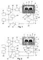
- Fig. 1 schematically illustrates a heat source 1 having an essentially hollow cylindrical oven block 2 made of silver.
- the upper face of oven block 2 is formed as a removable lid 3 for opening and closing block 2 to permit access to the interior 4 thereof.
- a winding of heating wire 5 is wound onto the exterior cylindrical surface of oven block 2 to provide for resistive heating.
- a flat resistive heater could be applied to the lower face of oven block 2 opposite to lid 3 or any other suitable portion of oven block 2.
- a disc-shaped substrate 6 is arranged in the interior of oven block 2 in thermal contact therewith.
- Substrate 6 has two circular areas thereof formed as a sample holder and a reference holder, respectively, adapted to support a sample pan 7 and a reference pan 8, respectively.
- Each of the circular areas of the sample and reference holders are formed with a thermocouple arrangement for detecting the temperatures T S and T R of the sample and reference pans 7, 8, respectively.
- the electrical signals representing the sample and reference temperatures T S and T R are fed to the outside of heat source 1 by means of signal lines 9 and 10, respectively.
- a platinum thermometer 11 arranged at the bottom portion of oven block 2 detects a temperature T F of oven block 2, and a corresponding electrical signal is fed to the outside by signal line 12. Electrical heating power is supplied to heater winding 5 of heat source 1 by a power amplifier 13.
- the signal on signal line 12 representing the measured temperature T F of heat source 1 is applied to the input of a filter 14 which produces a signal representative of an average temperature T Fav at an output thereof.
- This average temperature signal is applied to one input of a subtractor 15 via signal line 16.
- the other input terminal of subtractor 15 is connected to the output of a temperature programmer 17.
- Temperature programmer 17 outputs a first control signal which represents a temperature-versus-time function for heat source 1.
- the output signal of subtractor 15 being representative of the difference between the first control signal from temperature programmer 17 and the average temperature signal T Fav on signal line 16 is applied to a control input of a temperature controller 18 which generates a corresponding control signal for power amplifier 13.
- control loop formed by signal line 12, filter 14, signal line 16, temperature programmer 17, subtractor 15, temperature controller 18 and power amplifier 13 drives the heater winding 5 so that the average temperature T Fav of heat source 1 follows the temperature-versus-time function commanded by temperature programmer 17.
- the heat flow between a sample in sample pan 7 and the heat source 1 is proportional to a difference between the sample temperature T S and the heat source temperature T F
- the differential heat flow HF is proportional to the difference between sample and reference temperatures T S and T R , respectively.
- signal lines 9 and 10 carrying the sample and reference temperature signals T S and T R are connected to the input side of a subtractor 19 which produces a corresponding difference signal on the output side thereof.
- This difference signal is applied to a heat flow calculation unit 20, and the calculated heat flow HF and the measured sample temperature T S are fed to an evaluation unit (not shown) on signal lines 21 and 22, respectively, for further processing which includes the evaluation of a functional relation between heat flow HF and temperature T S .
- An alternative exemplary way of obtaining the heat flow HF is described herein below with reference to Fig. 7.
- a power modulation programmer 23 outputs a second control signal representing a periodic power modulation, e. g. in terms of a modulation amplitude and frequency of heating power applied to heat source 1.
- This second control signal is applied to a control input of a power modulation generator 24 to thereby command power modulation generator 24 to produce an output signal for controlling power amplifier 13 in accordance with the selected modulation.
- the modulation control signal from power modulation generator 24 is superposed on the temperature control signal from temperature controller 18 by means of an adder 25 having the input terminals thereof fed with the power modulation and temperature control signals and having the summing output thereof connected to the control input of power amplifier 13.
- the superposed control signal from power modulation generator 24 therefore results in a corresponding power modulation of the average heating power commanded by temperature controller 18.
- the embodiment schematically illustrated in Fig. 2 is a modification of the embodiment of Fig. 1, and identical reference numerals are used for the same parts of Figs 1 and 2.
- the embodiment of Fig. 2 is different from Fig. 1 by the additional provision of a heat flow demodulator 26 receiving the measured heat flow HF from heat flow calculation unit 20 and outputting a signal which represents a demodulated heat flow amplitude A HF of the measured heat flow HF.
- the controller further comprises a subtractor 27 having the signal representing the demodulated heat flow amplitude A HF and the second control signal from power modulation programmer 23 applied to the input terminals thereof and delivering a corresponding difference signal to power modulation generator 24.
- heat flow calculation unit 20 heat flow demodulator 26, subtractor 27, power modulation generator 24, adder 25 and power amplifier 13 form a second control loop in addition to the first control loop in Fig. 1.
- This second control loop causes a power modulation of heat source 1 so as to have the amplitude of the measured heat flow HF to assume the amplitude value set by power modulation programmer 23.
- Fig. 1 is similar to Fig. 2, and reference is in so far made to the above description of Fig. 1.
- Fig. 3 is different from Fig. 1 in that a separate heater 28 is formed with substrate 6 to extend over both of the sample and reference pan locations 7, 8.
- the separate heater 28 is energized by a separate power amplifier 29 via supply lines 30, 31.
- the separate power amplifier 29 is controlled by the control signal from power modulation generator 24 while the power amplifier 13 energizing heating winding 5 is controlled by the control signal from temperature controller 18.
- the power modulation is transferred to the sample and reference through the separate heater 28.
- Fig. 3 is similar to Fig. 1, and reference is in so far made to the above description of Fig. 1.
- Fig. 4 is a modification of the embodiment of Fig. 2, and identical reference numerals are used for the same parts of Figs 2 and 4.
- Fig. 4 is different from Fig. 2 in that a separate heater 28 is formed with substrate 6 to extend over both of the sample and reference pan locations 7, 8.
- the separate heater 28 is energized by a separate power amplifier 29 via supply lines 30, 31.
- the separate power amplifier 29 is controlled by the control signal from power modulation generator 24 while the power amplifier 13 energizing heating winding 5 is controlled by the control signal from temperature controller 18.
- the power modulation is transferred to the sample and reference through the separate heater 28.
- Fig. 4 is similar to Fig. 2, and reference is in so far made to the above description of Fig. 2.
- Figs 5 and 6 are modifications of the embodiments of Figs 3 and 4, respectively, and identical reference numerals are used for the same parts.
- the difference in Figs 5 and 6 as compared to corresponding Figs 3 and 4, respectively, is in the fact that separate heater 28 is only arranged for the sample location 7 and does not extend to the reference location 8 while the signals representing sample temperature T S and reference temperature T R on signal lines 9 and 10, respectively, are separately applied to heat flow calculation unit 20' and are separately applied to the evaluation unit (not shown) on signal lines 22, 22'.
- Figs 5 and 6 are similar to Figs 3 and 4, respectively, and reference is in so far made to the above description thereof.
- These signals may be evaluated so as to separate between the dynamical and average components to thereby establish separate relations between the dynamical and average components of heat flow HF and at least one of the temperature signal components to thereby collect an optimum amount of information on the physical parameters of the sample.
- the upper side of substrate 6 has two layers of strips 40, 41 of thermocouple ink printed thereon in a pattern so as to form a thermocouple composed of a plurality of series-connected thermosensitive junctions 42, 43 circularly arranged at a sample position S and a reference position R.
- the thermosensitive junctions 42, 43 are formed between overlapping portions of the lower and upper layers of strips 40, 41 of thermocouple ink. This produces two sets of thermosensitive junctions 42, 43 located on two concentric circles of different radius for each of said sample and reference positions.
- the thermosensitive junctions 42 and 43 of the two circles are circumferentially spaced under the same angular distance but mutually staggered at half of this angular distance.
- thermosensitive junction 43 on the outer circle is connected with two thermosensitive junctions 42 on the inner circle by a lower layer strip 40 of thermocouple ink and an upper layer strip 41, respectively, the circumferential offset between these connected junctions being one half of the angular distance between the thermosensitive junctions of each circle.
- connection pads 44, 45 are located diametrically opposite an imaginary connecting line between the centers of said sample and reference positions S, R.
- Fig. 7 further shows for each of said sample and reference positions S, R two diametrically opposite strips 46, 47 in the form of portions of a circle concentrically arranged with the inner and outer circular loci of thermosensitive junctions 42, 43 and radially outside the locus of thermosensitive junctions 43. These two strips 46, 47 act as positional aids to concentrically position a sample pan and reference pan, respectively.
- thermocouple ink The pattern of strips 40, 41 of thermocouple ink, connection pads 44, 45 including their interconnections and strips 46 and 47 is embedded into a dielectric material providing for electric insulation and is covered by a protective overglaze.
- thermosensitive junctions 43 and 42 the flow path of heat extends across the radial outer circle of thermosensitive junctions 43 and the inner circle of thermosensitive junctions 42.
- This flow of heat causes a temperature difference to occur between the radially outer and inner thermosensitive junctions 43 and 42, respectively, and the thermocouple formed of the series connection of these thermosensitive junctions 42 and 43 generates an electrical output signal in proportion to said temperature difference.
- a signal portion associated with the heat flow to reference position R is subtracted from the heat flow to sample position S thereby forming a differential heat flow signal.
Landscapes
- Chemical & Material Sciences (AREA)
- Engineering & Computer Science (AREA)
- Chemical Kinetics & Catalysis (AREA)
- Combustion & Propulsion (AREA)
- Physics & Mathematics (AREA)
- Health & Medical Sciences (AREA)
- Life Sciences & Earth Sciences (AREA)
- Analytical Chemistry (AREA)
- Biochemistry (AREA)
- General Health & Medical Sciences (AREA)
- General Physics & Mathematics (AREA)
- Immunology (AREA)
- Pathology (AREA)
- Investigating Or Analyzing Materials Using Thermal Means (AREA)
- Measuring Temperature Or Quantity Of Heat (AREA)
Claims (20)
- Procédé pour l'analyse thermique d'un matériau, comprenant les étapes qui consistent :à établir un trajet de flux de chaleur entre un échantillon dudit matériau et une source de chaleur pour provoquer ainsi un flux de chaleur entre ledit échantillon et ladite source de chaleur ;à commander la puissance de chauffage de ladite source de chaleur en fonction du temps ;à mesurer un signal représentatif dudit flux de chaleur entre ledit échantillon et ladite source de chaleur et un signal représentatif d'une température associée audit flux de chaleur ; età évaluer une relation fonctionnelle entre ledit flux de chaleur mesuré et les signaux de température ; dans lequelladite étape de commande de ladite puissance de chauffage est basée sur une première entrée de commande pour amener ladite source de chaleur à prendre une température prédéterminée en fonction du temps et sur une seconde entrée de commande pour moduler la puissance de chauffage de ladite source de chaleur engendrée par ladite première entrée de commande conformément à une modulation de puissance périodique sélectionnée.
- Procédé selon la revendication 1, dans lequel ladite seconde entrée de commande est destinée à établir une amplitude prédéterminée de ladite modulation de puissance.
- Procédé selon la revendication 1, dans lequel ladite seconde entrée de commande est destinée à déterminer ladite modulation de puissance afin d'aboutir à une amplitude prédéterminée dudit flux de chaleur mesuré.
- Procédé selon l'une quelconque des revendications 1 à 3, comprenant en outre les étapes qui consistent :à mesurer une température de ladite source de chaleur ;à filtrer ladite température mesurée pour obtenir ainsi une température moyenne correspondant à la puissance de chauffage non modulée de ladite source de chaleur ; età utiliser un signal représentatif d'une différence entre ladite température moyenne et ladite première entrée de commande en tant que signal de commande de puissance de chauffage pour ladite source de chaleur.
- Procédé selon l'une des revendications 3 ou 4, comprenant en outre les étapes qui consistent :à démoduler ledit signal de flux de chaleur mesuré pour obtenir ainsi une amplitude dudit flux de chaleur engendré par ladite modulation de puissance ; età utiliser un signal représentatif d'une différence entre ladite amplitude démodulée et ladite seconde entrée de commande en tant que signal de commande de puissance de chauffage pour ladite source de chaleur.
- Procédé selon l'une quelconque des revendications 1 à 5, comprenant en outre les étapes qui consistent :à utiliser une source de chaleur complémentaire en plus de ladite source de chaleur ;à commander ladite source de chaleur conformément à ladite première entrée de commande ; età commander ladite source de chaleur complémentaire conformément à ladite seconde entrée de commande.
- Procédé selon l'une quelconque des revendications 1 à 6, dans lequel ledit signal représentatif d'un flux de chaleur est un signal différentiel correspondant à une différence de flux de chaleur entre ledit échantillon et ladite source de chaleur et à un matériau de référence et à ladite source de chaleur.
- Procédé selon les revendications 6 et 7, dans lequel ladite source de chaleur supplémentaire est associée uniquement audit échantillon.
- Procédé selon l'une quelconque des revendications 1 à 8, dans lequel ladite étape d'évaluation d'une relation fonctionnelle entre ledit flux de chaleur mesuré et les signaux de température comprend les étapes qui consistent :à obtenir une composante moyenne d'au moins l'un dudit flux de chaleur mesuré et d'une vitesse de chauffage dérivée de ladite température mesurée associée audit flux de chaleur sur un intervalle de temps sélectionné ;à obtenir une composante dynamique d'au moins l'un dudit flux de chaleur et de la vitesse de chauffage sous la forme d'une différence entre ledit flux de chaleur mesuré ou la vitesse de chauffage obtenue, respectivement, et ladite composante moyenne obtenue respective ;à obtenir une température moyenne de ladite température mesurée associée audit flux de chaleur sur ledit intervalle de temps sélectionné ; età représenter ladite composante dynamique sous la forme d'une fonction de ladite température moyenne obtenue.
- Procédé selon l'une quelconque des revendications 1 à 9, dans lequel ladite étape de mesure d'un signal représentatif dudit flux de chaleur comprend l'étape consistant à mesurer une différence de température entre au moins deux emplacements espacés d'une certaine distance le long dudit trajet du flux de chaleur.
- Appareil pour l'analyse thermique d'un matériau, comportant :ladite unité de commande comporte un moyen (17) destiné à établir un premier signal de commande représentant un programme de température sélectionné de ladite source de chaleur (1) en fonction du temps et un moyen (23) destiné à établir un second signal de commande pour moduler ladite puissance de chauffage engendrée par ledit premier signal de commande, conformément à une modulation de puissance périodique sélectionnée.une source de chaleur (1) ;un substrat (6) ayant un porte-échantillon couplé thermiquement à ladite source de chaleur (1, 2) pour établir ainsi un trajet de flux de chaleur pour un flux de chaleur entre ladite source de chaleur (1) et un échantillon dans ledit porte-échantillon ;une unité de commande destinée à commander la puissance de chauffage de ladite source de chaleur (1) en fonction du temps ;un moyen (9) destiné à mesurer un signal représentatif dudit flux de chaleur (HF) entre ledit échantillon dans ladite position d'échantillon et ladite source de chaleur ;un moyen (11, 12) destiné à mesurer un signal représentatif d'une température associée audit flux de chaleur (HF) ;et un moyen destiné à évaluer une relation fonctionnelle entre ledit flux de chaleur mesuré et les signaux de température ; dans lequel
- Appareil selon la revendication 11, dans lequel ladite unité de commande comporteun filtre (14) à une entrée duquel est appliqué un signal représentatif d'une température mesurée (Tf) de ladite source de chaleur (1) et qui produit à sa sortie un signal représentatif d'une température moyenne (TFav) de ladite source de chaleur (1) ; etun soustracteur (15) à une entrée duquel est appliqué ledit premier signal de commande et à l'autre entrée duquel est appliqué ledit signal de température moyenne (TFav), et qui produit à sa sortie un signal de commande de température pour ladite source de chaleur (1).
- Appareil selon l'une des revendications 11 ou 12, dans lequel ladite unité de commande comporteun démodulateur (26) de flux de chaleur destiné à dériver une amplitude de modulation (AHF) dudit flux de chaleur mesuré (HF) ; etun soustracteur (27) à une entrée duquel est appliqué ledit second signal de commande et à l'autre entrée duquel est appliquée ladite amplitude de modulation dérivée (AHF), et qui produit à sa sortie un signal de commande de modulation pour ladite source de chaleur (1).
- Appareil selon l'une quelconque des revendications 11 à 13, dans lequel ladite source de chaleur (1) comporte un premier élément chauffant (5) commandé conformément audit premier signal de commande et un second élément chauffant (28) commandé conformément audit second signal de commande.
- Appareil selon l'une quelconque des revendications 11 à 14, dans lequelledit substrat (6) comporte un support de référence couplé thermiquement à ladite source de chaleur (1) pour établir ainsi un trajet de flux de chaleur pour un flux de chaleur entre ladite source de chaleur (1) et une référence dans ledit porte-référence ;et comportant en outreun moyen (19) destiné à mesurer une différence de température entre ledit porte-échantillon et ledit porte-référence.
- Appareil selon les revendications 14 et 15, dans lequel ladite seconde source de chaleur (28) est associée uniquement audit porte-échantillon.
- Appareil selon l'une quelconque des revendications 11 à 16, dans lequel ledit moyen destiné à mesurer un signal représentatif dudit flux de chaleur comprend un moyen destiné à mesurer une différence de température entre au moins deux emplacements espacés d'une certaine distance le long dudit trajet du flux de chaleur.
- Appareil selon la revendication 17, dans lequel ledit moyen destiné à mesurer ladite différence de température est formé par un thermocouple ayant au moins deux jonctions thermosensibles (42, 43) positionnées le long dudit trajet du flux de chaleur, l'une desdites jonctions étant plus proche dudit porte-échantillon que l'autre.
- Appareil selon la revendication 18, dans lequel ledit thermocouple comporte deux ensembles de jonctions thermosensibles (42, 43) connectées alternativement en série, agencées sur deux cercles concentriques centrés sur ledit porte-échantillon.
- Calorimètre selon l'une quelconque des revendications 11 à 19, dans lequel ledit porte-échantillon est conçu pour recevoir en contact thermique un bac (7) à échantillon, ledit bac (7) à échantillon étant formé de façon à recevoir en lui ledit échantillon.
Priority Applications (5)
| Application Number | Priority Date | Filing Date | Title |
|---|---|---|---|
| DE60024774T DE60024774T2 (de) | 2000-02-03 | 2000-02-03 | Modulationsverfahren und Vorrichtung für die Thermoanalyse eines Materials |
| EP00102396A EP1132733B1 (fr) | 2000-02-03 | 2000-02-03 | Procédé de modulation et dispositif pour l'analyse thermique d'un matériau |
| AT00102396T ATE313073T1 (de) | 2000-02-03 | 2000-02-03 | Modulationsverfahren und vorrichtung für die thermoanalyse eines materials |
| JP2001016067A JP2001249093A (ja) | 2000-02-03 | 2001-01-24 | 物質を熱的に分析するための変調方法及び装置 |
| US09/773,783 US6583391B2 (en) | 2000-02-03 | 2001-01-31 | Modulation method and apparatus for thermally analyzing a material |
Applications Claiming Priority (1)
| Application Number | Priority Date | Filing Date | Title |
|---|---|---|---|
| EP00102396A EP1132733B1 (fr) | 2000-02-03 | 2000-02-03 | Procédé de modulation et dispositif pour l'analyse thermique d'un matériau |
Publications (2)
| Publication Number | Publication Date |
|---|---|
| EP1132733A1 EP1132733A1 (fr) | 2001-09-12 |
| EP1132733B1 true EP1132733B1 (fr) | 2005-12-14 |
Family
ID=8167776
Family Applications (1)
| Application Number | Title | Priority Date | Filing Date |
|---|---|---|---|
| EP00102396A Expired - Lifetime EP1132733B1 (fr) | 2000-02-03 | 2000-02-03 | Procédé de modulation et dispositif pour l'analyse thermique d'un matériau |
Country Status (5)
| Country | Link |
|---|---|
| US (1) | US6583391B2 (fr) |
| EP (1) | EP1132733B1 (fr) |
| JP (1) | JP2001249093A (fr) |
| AT (1) | ATE313073T1 (fr) |
| DE (1) | DE60024774T2 (fr) |
Families Citing this family (17)
| Publication number | Priority date | Publication date | Assignee | Title |
|---|---|---|---|---|
| ITVE20020012A1 (it) * | 2002-03-13 | 2003-09-15 | Alper Srl | Emanatore elettrico di deodorante o di insetticida. |
| ATE521886T1 (de) * | 2002-06-10 | 2011-09-15 | Mettler Toledo Ag | Verfahren und vorrichtung für die thermische analyse eines materials |
| KR100814414B1 (ko) * | 2003-09-01 | 2008-03-18 | 학교법인 포항공과대학교 | 발열량 측정장치 및 방법 |
| ATE371862T1 (de) | 2003-10-28 | 2007-09-15 | Mettler Toledo Ag | Thermoanalytischer sensor und verfahren zu dessen herstellung |
| JP4116526B2 (ja) * | 2003-11-18 | 2008-07-09 | エスアイアイ・ナノテクノロジー株式会社 | 第二のヒーターを備えた示差走査熱量計 |
| FR2886730B1 (fr) * | 2005-06-02 | 2007-07-27 | Inst Francais Du Petrole | Methode d'analyse de la cinetique de formation d'hydrates de gaz dans des fluides |
| US7470057B2 (en) * | 2006-08-24 | 2008-12-30 | Waters Investments Limited | Differential scanning calorimeter sensor and method |
| ATE501433T1 (de) * | 2008-06-13 | 2011-03-15 | Mettler Toledo Ag | Wärmeanalyseinstrument mit dynamischer leistungskompensation |
| FR2938652B1 (fr) * | 2008-11-14 | 2011-11-25 | Commissariat Energie Atomique | Four d'essai de materiaux et procede de caracterisation utilisant ce four |
| US8147133B2 (en) * | 2009-05-26 | 2012-04-03 | The United States Of America As Represented By The Secretary Of The Navy | Top loaded twin cell calorimeter system with removable reference |
| JP5526230B2 (ja) * | 2009-07-14 | 2014-06-18 | コーニンクレッカ フィリップス エヌ ヴェ | 接触検出装置及びその動作方法 |
| DE102012005414B4 (de) | 2011-03-14 | 2018-08-23 | Technische Universität Ilmenau | Verfahren zur automatischen Detektion einer Phasenumwandlung mit Energieumsatz |
| CN102534567B (zh) * | 2012-03-21 | 2014-01-15 | 中微半导体设备(上海)有限公司 | 控制化学气相沉积腔室内的基底加热的装置及方法 |
| DE102013102088B3 (de) * | 2013-03-04 | 2014-07-17 | Netzsch-Gerätebau GmbH | Verfahren und Vorrichtung zur Materialanalyse |
| EP2976610B1 (fr) | 2013-03-22 | 2018-08-15 | Waters Technologies Corporation | Capteur pour analyseur calorimétrique différentiel à thermopile |
| US9389194B2 (en) * | 2013-09-13 | 2016-07-12 | Netzsch-Geraetebau Gmbh | System and method for analysis in modulated thermogravimetry |
| EP2921833B1 (fr) * | 2014-03-18 | 2016-12-28 | Mettler-Toledo GmbH | Capteur thermo-analytique et procédé destiné à sa fabrication |
Citations (1)
| Publication number | Priority date | Publication date | Assignee | Title |
|---|---|---|---|---|
| EP1091208A1 (fr) * | 1999-09-27 | 2001-04-11 | Mettler-Toledo GmbH | Procédé et dispositif d'analyse thermique d'un matériau |
Family Cites Families (9)
| Publication number | Priority date | Publication date | Assignee | Title |
|---|---|---|---|---|
| US5224775C2 (en) * | 1992-03-02 | 2002-04-23 | Ta Instr Inc | Method and apparatus for modulated differential analysis |
| US5624187A (en) * | 1992-03-02 | 1997-04-29 | Ta Instruments, Inc. | Method and apparatus for gas flow modulated differential scanning calorimetry |
| US5474385A (en) * | 1992-03-02 | 1995-12-12 | Ta Instruments, Inc. | Method and apparatus for parsed dynamic differential analysis |
| US5288147A (en) * | 1992-11-09 | 1994-02-22 | Ta Instruments, Inc. | Thermopile differential thermal analysis sensor |
| JP2909950B2 (ja) * | 1993-09-24 | 1999-06-23 | セイコーインスツルメンツ株式会社 | 熱分析装置 |
| US5549387A (en) | 1994-06-01 | 1996-08-27 | The Perkin-Elmer Corporation | Apparatus and method for differential analysis using real and imaginary signal components |
| EP0803061B1 (fr) | 1994-06-01 | 2004-05-06 | Perkin-Elmer Corporation | Appareil et procede d'analyse diffentielle utilisant les composants de signaux imaginaires et reels |
| US5672289A (en) * | 1996-01-11 | 1997-09-30 | The Perkin-Elmer Corporation | Heater control circuit |
| JP3137605B2 (ja) * | 1998-07-14 | 2001-02-26 | セイコーインスツルメンツ株式会社 | 熱流束型示差走査熱量計 |
-
2000
- 2000-02-03 DE DE60024774T patent/DE60024774T2/de not_active Expired - Lifetime
- 2000-02-03 EP EP00102396A patent/EP1132733B1/fr not_active Expired - Lifetime
- 2000-02-03 AT AT00102396T patent/ATE313073T1/de not_active IP Right Cessation
-
2001
- 2001-01-24 JP JP2001016067A patent/JP2001249093A/ja active Pending
- 2001-01-31 US US09/773,783 patent/US6583391B2/en not_active Expired - Lifetime
Patent Citations (1)
| Publication number | Priority date | Publication date | Assignee | Title |
|---|---|---|---|---|
| EP1091208A1 (fr) * | 1999-09-27 | 2001-04-11 | Mettler-Toledo GmbH | Procédé et dispositif d'analyse thermique d'un matériau |
Also Published As
| Publication number | Publication date |
|---|---|
| JP2001249093A (ja) | 2001-09-14 |
| EP1132733A1 (fr) | 2001-09-12 |
| DE60024774T2 (de) | 2006-09-07 |
| DE60024774D1 (de) | 2006-01-19 |
| US20010019049A1 (en) | 2001-09-06 |
| ATE313073T1 (de) | 2005-12-15 |
| US6583391B2 (en) | 2003-06-24 |
Similar Documents
| Publication | Publication Date | Title |
|---|---|---|
| EP1132733B1 (fr) | Procédé de modulation et dispositif pour l'analyse thermique d'un matériau | |
| US6318890B1 (en) | Single cell calorimeter | |
| EP0498063B1 (fr) | Circuit pour chauffer et capter la température avec une résistance unique | |
| KR100292221B1 (ko) | 복수의식품재료를균일하게가열하기위한방법및가열조리장치 | |
| US4447710A (en) | Electric cookers incorporating radiant heaters | |
| EP1091208B1 (fr) | Procédé et dispositif d'analyse thermique d'un matériau | |
| US5227610A (en) | Process and device for indicating an anomalous thermal stress condition in a heating surface made from glass ceramic or a comparable material | |
| WO2002047821A1 (fr) | Plaque de microtitrage a dispositif de chauffage integre | |
| US6530686B1 (en) | Differential scanning calorimeter having low drift and high response characteristics | |
| EP1371973B1 (fr) | Procédé et dispositif d'analyse thermique d'un matériau | |
| US5225766A (en) | High impedance current source | |
| US20190223258A1 (en) | Method for operating a heating element | |
| US3747396A (en) | Linearizing circuit for a ramp generator in a differential scanning calorimeter | |
| GB2103910A (en) | Improvements in electric cookers incorporating radiant heaters | |
| WO1995016230A1 (fr) | Dispositif de commande de temperature de fonctionnement dans une zone de cuisson | |
| JPH05223763A (ja) | 熱電対を用いた熱分析装置 | |
| EP4343295A1 (fr) | Ensemble capteur pour calorimètre à balayage différentiel | |
| US7316505B2 (en) | Method of defining the emission coefficient of a surface to be heated | |
| EP4548711A1 (fr) | Dispositif de cuisson par induction et son procédé de commande | |
| WO2024005761A1 (fr) | Dispositif de cuisson par induction et son procédé de commande | |
| JPS6381253A (ja) | 試料単独方式の熱流束型示差走査熱量計 | |
| GB2332072A (en) | Controlling heating element usable for flow or thermal conductivity measurement | |
| SU1168912A1 (ru) | Способ программного регулировани температуры и устройство дл его осуществлени | |
| JPH0136115Y2 (fr) | ||
| JPH0627060A (ja) | 熱測定装置 |
Legal Events
| Date | Code | Title | Description |
|---|---|---|---|
| PUAI | Public reference made under article 153(3) epc to a published international application that has entered the european phase |
Free format text: ORIGINAL CODE: 0009012 |
|
| 17P | Request for examination filed |
Effective date: 20010115 |
|
| AK | Designated contracting states |
Kind code of ref document: A1 Designated state(s): AT BE CH CY DE DK ES FI FR GB GR IE IT LI LU MC NL PT SE |
|
| AX | Request for extension of the european patent |
Free format text: AL;LT;LV;MK;RO;SI |
|
| AKX | Designation fees paid |
Free format text: AT BE CH CY DE DK ES FI FR GB GR IE IT LI LU MC NL PT SE |
|
| GRAP | Despatch of communication of intention to grant a patent |
Free format text: ORIGINAL CODE: EPIDOSNIGR1 |
|
| GRAS | Grant fee paid |
Free format text: ORIGINAL CODE: EPIDOSNIGR3 |
|
| GRAA | (expected) grant |
Free format text: ORIGINAL CODE: 0009210 |
|
| AK | Designated contracting states |
Kind code of ref document: B1 Designated state(s): AT BE CH CY DE DK ES FI FR GB GR IE IT LI LU MC NL PT SE |
|
| PG25 | Lapsed in a contracting state [announced via postgrant information from national office to epo] |
Ref country code: IT Free format text: LAPSE BECAUSE OF FAILURE TO SUBMIT A TRANSLATION OF THE DESCRIPTION OR TO PAY THE FEE WITHIN THE PRESCRIBED TIME-LIMIT;WARNING: LAPSES OF ITALIAN PATENTS WITH EFFECTIVE DATE BEFORE 2007 MAY HAVE OCCURRED AT ANY TIME BEFORE 2007. THE CORRECT EFFECTIVE DATE MAY BE DIFFERENT FROM THE ONE RECORDED. Effective date: 20051214 Ref country code: FI Free format text: LAPSE BECAUSE OF FAILURE TO SUBMIT A TRANSLATION OF THE DESCRIPTION OR TO PAY THE FEE WITHIN THE PRESCRIBED TIME-LIMIT Effective date: 20051214 Ref country code: NL Free format text: LAPSE BECAUSE OF FAILURE TO SUBMIT A TRANSLATION OF THE DESCRIPTION OR TO PAY THE FEE WITHIN THE PRESCRIBED TIME-LIMIT Effective date: 20051214 Ref country code: BE Free format text: LAPSE BECAUSE OF FAILURE TO SUBMIT A TRANSLATION OF THE DESCRIPTION OR TO PAY THE FEE WITHIN THE PRESCRIBED TIME-LIMIT Effective date: 20051214 Ref country code: AT Free format text: LAPSE BECAUSE OF FAILURE TO SUBMIT A TRANSLATION OF THE DESCRIPTION OR TO PAY THE FEE WITHIN THE PRESCRIBED TIME-LIMIT Effective date: 20051214 |
|
| REG | Reference to a national code |
Ref country code: GB Ref legal event code: FG4D |
|
| REG | Reference to a national code |
Ref country code: CH Ref legal event code: EP |
|
| REG | Reference to a national code |
Ref country code: IE Ref legal event code: FG4D |
|
| REF | Corresponds to: |
Ref document number: 60024774 Country of ref document: DE Date of ref document: 20060119 Kind code of ref document: P |
|
| PG25 | Lapsed in a contracting state [announced via postgrant information from national office to epo] |
Ref country code: IE Free format text: LAPSE BECAUSE OF NON-PAYMENT OF DUE FEES Effective date: 20060203 |
|
| PG25 | Lapsed in a contracting state [announced via postgrant information from national office to epo] |
Ref country code: LU Free format text: LAPSE BECAUSE OF NON-PAYMENT OF DUE FEES Effective date: 20060228 Ref country code: MC Free format text: LAPSE BECAUSE OF NON-PAYMENT OF DUE FEES Effective date: 20060228 |
|
| PG25 | Lapsed in a contracting state [announced via postgrant information from national office to epo] |
Ref country code: SE Free format text: LAPSE BECAUSE OF FAILURE TO SUBMIT A TRANSLATION OF THE DESCRIPTION OR TO PAY THE FEE WITHIN THE PRESCRIBED TIME-LIMIT Effective date: 20060314 Ref country code: GR Free format text: LAPSE BECAUSE OF FAILURE TO SUBMIT A TRANSLATION OF THE DESCRIPTION OR TO PAY THE FEE WITHIN THE PRESCRIBED TIME-LIMIT Effective date: 20060314 Ref country code: DK Free format text: LAPSE BECAUSE OF FAILURE TO SUBMIT A TRANSLATION OF THE DESCRIPTION OR TO PAY THE FEE WITHIN THE PRESCRIBED TIME-LIMIT Effective date: 20060314 |
|
| PG25 | Lapsed in a contracting state [announced via postgrant information from national office to epo] |
Ref country code: ES Free format text: LAPSE BECAUSE OF FAILURE TO SUBMIT A TRANSLATION OF THE DESCRIPTION OR TO PAY THE FEE WITHIN THE PRESCRIBED TIME-LIMIT Effective date: 20060325 |
|
| PG25 | Lapsed in a contracting state [announced via postgrant information from national office to epo] |
Ref country code: PT Free format text: LAPSE BECAUSE OF FAILURE TO SUBMIT A TRANSLATION OF THE DESCRIPTION OR TO PAY THE FEE WITHIN THE PRESCRIBED TIME-LIMIT Effective date: 20060515 |
|
| NLV1 | Nl: lapsed or annulled due to failure to fulfill the requirements of art. 29p and 29m of the patents act | ||
| ET | Fr: translation filed | ||
| REG | Reference to a national code |
Ref country code: CH Ref legal event code: PFA Owner name: METTLER-TOLEDO AG Free format text: METTLER-TOLEDO GMBH#IM LANGACHER#8606 GREIFENSEE (CH) -TRANSFER TO- METTLER-TOLEDO AG#IM LANGACHER#8606 GREIFENSEE (CH) |
|
| PLBE | No opposition filed within time limit |
Free format text: ORIGINAL CODE: 0009261 |
|
| STAA | Information on the status of an ep patent application or granted ep patent |
Free format text: STATUS: NO OPPOSITION FILED WITHIN TIME LIMIT |
|
| 26N | No opposition filed |
Effective date: 20060915 |
|
| PGFP | Annual fee paid to national office [announced via postgrant information from national office to epo] |
Ref country code: CH Payment date: 20070214 Year of fee payment: 8 |
|
| PGFP | Annual fee paid to national office [announced via postgrant information from national office to epo] |
Ref country code: GB Payment date: 20070216 Year of fee payment: 8 |
|
| REG | Reference to a national code |
Ref country code: FR Ref legal event code: CJ Ref country code: FR Ref legal event code: CD |
|
| REG | Reference to a national code |
Ref country code: CH Ref legal event code: PL |
|
| GBPC | Gb: european patent ceased through non-payment of renewal fee |
Effective date: 20080203 |
|
| PG25 | Lapsed in a contracting state [announced via postgrant information from national office to epo] |
Ref country code: CH Free format text: LAPSE BECAUSE OF NON-PAYMENT OF DUE FEES Effective date: 20080229 Ref country code: LI Free format text: LAPSE BECAUSE OF NON-PAYMENT OF DUE FEES Effective date: 20080229 |
|
| PG25 | Lapsed in a contracting state [announced via postgrant information from national office to epo] |
Ref country code: CY Free format text: LAPSE BECAUSE OF FAILURE TO SUBMIT A TRANSLATION OF THE DESCRIPTION OR TO PAY THE FEE WITHIN THE PRESCRIBED TIME-LIMIT Effective date: 20051214 |
|
| PG25 | Lapsed in a contracting state [announced via postgrant information from national office to epo] |
Ref country code: GB Free format text: LAPSE BECAUSE OF NON-PAYMENT OF DUE FEES Effective date: 20080203 |
|
| REG | Reference to a national code |
Ref country code: FR Ref legal event code: PLFP Year of fee payment: 16 |
|
| PGFP | Annual fee paid to national office [announced via postgrant information from national office to epo] |
Ref country code: DE Payment date: 20150227 Year of fee payment: 16 |
|
| PGFP | Annual fee paid to national office [announced via postgrant information from national office to epo] |
Ref country code: FR Payment date: 20150126 Year of fee payment: 16 |
|
| REG | Reference to a national code |
Ref country code: DE Ref legal event code: R119 Ref document number: 60024774 Country of ref document: DE |
|
| REG | Reference to a national code |
Ref country code: FR Ref legal event code: ST Effective date: 20161028 |
|
| PG25 | Lapsed in a contracting state [announced via postgrant information from national office to epo] |
Ref country code: FR Free format text: LAPSE BECAUSE OF NON-PAYMENT OF DUE FEES Effective date: 20160229 Ref country code: DE Free format text: LAPSE BECAUSE OF NON-PAYMENT OF DUE FEES Effective date: 20160901 |