EP1132756A2 - Gamma-caméras avec corrections pour la radiation transmise - Google Patents
Gamma-caméras avec corrections pour la radiation transmise Download PDFInfo
- Publication number
- EP1132756A2 EP1132756A2 EP01302241A EP01302241A EP1132756A2 EP 1132756 A2 EP1132756 A2 EP 1132756A2 EP 01302241 A EP01302241 A EP 01302241A EP 01302241 A EP01302241 A EP 01302241A EP 1132756 A2 EP1132756 A2 EP 1132756A2
- Authority
- EP
- European Patent Office
- Prior art keywords
- radiation
- transmission
- radiation source
- emission
- gantry
- Prior art date
- Legal status (The legal status is an assumption and is not a legal conclusion. Google has not performed a legal analysis and makes no representation as to the accuracy of the status listed.)
- Withdrawn
Links
Images



Classifications
-
- G—PHYSICS
- G01—MEASURING; TESTING
- G01T—MEASUREMENT OF NUCLEAR OR X-RADIATION
- G01T1/00—Measuring X-radiation, gamma radiation, corpuscular radiation, or cosmic radiation
- G01T1/16—Measuring radiation intensity
- G01T1/161—Applications in the field of nuclear medicine, e.g. in vivo counting
- G01T1/164—Scintigraphy
- G01T1/1641—Static instruments for imaging the distribution of radioactivity in one or two dimensions using one or several scintillating elements; Radio-isotope cameras
- G01T1/1648—Ancillary equipment for scintillation cameras, e.g. reference markers, devices for removing motion artifacts, calibration devices
Definitions
- the present invention relates to the field of nuclear medicine and diagnostic imaging. It finds particular application in conjunction with gamma cameras and will be described with particular reference thereto. It is to be appreciated that the present invention is applicable to single photon emission computed tomography (SPECT), positron emission tomography (PET), whole body nuclear scans, and/or other like applications.
- SPECT single photon emission computed tomography
- PET positron emission tomography
- whole body nuclear scans and/or other like applications.
- Diagnostic nuclear imaging is used to study a radionuclide distribution in a subject.
- one or more radiopharmaceuticals or radioisotopes are injected into a subject.
- the radiopharmaceuticals are commonly injected into the subject's blood stream for imaging the circulatory system or for imaging specific organs which absorb the injected radiopharmaceuticals.
- Gamma or scintillation camera detector heads typically including collimators, are placed adjacent to a surface of the subject to monitor and record emitted radiation. For three-dimensional reconstruction, the detector heads are rotated or indexed around the subject to monitor the emitted radiation from a plurality of directions.
- SPECT emission radiation is detected by each collimated detector.
- PET data collection is limited to emission radiation that is detected concurrently by a pair of oppositely disposed heads. The monitored radiation data from the multiplicity of directions is reconstructed into a three dimensional image representation of the radiopharmaceutical distribution within the subject.
- One of the problems with these imaging techniques is that photon absorption and scatter by portions of the subject or subject support between the emitting radionuclide and the detector heads distort the resultant image.
- One solution for compensating for photon attenuation is to assume uniform photon attenuation throughout the subject. That is, the subject is assumed to be completely homogeneous in terms of radiation attenuation with no distinction made for bone, soft tissue, lung, etc. This enables attenuation estimates to be made based on the surface contour of the subject.
- human subjects do not cause uniform radiation attenuation, especially in the chest.
- a direct transmission radiation attenuation measurement is made using transmission computed tomography techniques. More specifically, radiation is projected from a radiation source through the subject. Attenuated radiation rays are received by the detector at the opposite side. The source and detectors are rotated to collect transmission data concurrently or sequentially with the emission data through a multiplicity of angles. This transmission data is reconstructed into an image representation using conventional tomography algorithms. Regional radiation attenuation properties of the subject and the support, which are derived from the transmission computed tomography image, are used to correct or compensate for radiation attenuation in the emission data.
- SPECT and PET measurements are typically made at incrementally stepped locations.
- One difficulty resides in optimizing the sampling of both the SPECT or PET emission data and the transmission data so as to reduce overall scan time.
- nuclear camera detector heads are stepped to a plurality of positions around the patient, e.g. 60 positions. At each position, emission and/or transmission radiation data is collected.
- the total time to perform a transmission scan is composed of the time to actually acquire data at each angular orientation and the time to mechanically rotate the gantry from one angular orientation to another and stabilize it at the new orientation.
- these two components are of a similar order of magnitude, e.g. 4-5 seconds for data collection at each angular orientation and approximately 2-4 seconds for gantry rotation to each angular orientation and stabilization.
- a wait time for stabilization of only 2-4 seconds per step adds 4-8 minutes to a 120 step scan.
- a method of diagnostic imaging using a nuclear medicine gamma camera includes placing a subject in a subject receiving aperture and injecting the subject with a radiopharmaceutical. At least one radiation source and a plurality of radiation detectors are positioned about the subject receiving aperture such that the radiation source is across the subject receiving aperture from a corresponding radiation detector. Radiation from the radiation source is transmitted toward the corresponding radiation detector which is positioned across the subject receiving aperture. The at least one radiation source is rastered across the field of view. The at least one radiation source and radiation detectors are rotated together about the subject receiving aperture. Radiation transmitted by the radiation source is detected using one of the plurality of radiation detectors and reconstructed into an attenuation volume image representation. Radiation emitted by the injected radiopharmaceutical is detected using the plurality of radiation detectors and reconstructed into an image representation.
- a nuclear medicine gamma camera for diagnostic imaging includes a rotating gantry which defines a subject receiving aperture.
- a plurality of radiation detectors are movably attached to the rotating gantry such that the detector heads rotate about the subject receiving aperture with rotation of the rotating gantry about an axis of rotation.
- At least one radiation source is mounted to at least one detector head for rotation therewith such that transmission radiation from the radiation source is directed toward and received by a corresponding detector head positioned across the subject receiving aperture from the radiation source.
- the radiation source is rastered back and forth in a direction parallel to that of the axis of rotation.
- a raster sensor detects rastering of the radiation source across a field of view and a gantry sensor detects gantry rotation about the subject receiving aperture.
- a reconstruction processor reconstructs a volumetric emission image representation from the detected emission and transmission data, the sensed rastering of the radiation source, and the sensed gantry rotation.
- One advantage of the present invention is that it reduces gantry dead time.
- Another advantage of the present invention is that it makes it possible to reduce overall transmission scan time by approximately 50%.
- Another advantage of the present invention is that it permits greater resolution for SPECT emission data to be attained than is required for transmission data.
- a diagnostic imaging apparatus includes a subject support 10 , such as a table or couch, which supports a subject 12 being examined or imaged.
- the subject 12 is injected with one or more radiopharmaceuticals or radioisotopes such that emission radiation is emitted therefrom.
- the subject support 10 is selectively height adjustable so as to center the subject 12 at a desired height, e.g., the volume of interest is centered.
- a first or stationary gantry 14 rotatably supports a rotating gantry 16 .
- the rotating gantry 16 defines a subject receiving aperture 18 .
- the first gantry 14 is moved longitudinally along the subject support 10 so as to selectively position regions of interest of the subject 12 within the subject receiving aperture 18 .
- the subject support 10 is advanced and retracted to achieve the desired positioning of the subject 12 within the subject receiving aperture 18 .
- Detector heads 20a, 20b, 20c are individually positionable on the rotating gantry 16 .
- the detector heads 20a-20c also rotate as a group about the subject receiving aperture 18 (and the subject 12 when received) with the rotation of the rotating gantry 16 .
- the detector heads 20a-20c are radially and circumferentially adjustable to vary their distance from the subject and spacing on the rotating gantry 16 , as for example, in the manner disclosed in U.S. Patent No. 5,717,212.
- Separate translation devices 22a, 22b, 22c such as motors and drive assemblies, independently translate the detector heads radially and laterally in directions tangential to the subject receiving aperture 18 along linear tracks or other appropriate guides.
- Each of the detector heads 20a-20c has a radiation receiving face facing the subject receiving aperture 18 .
- Each head includes a scintillation crystal, such as a large doped sodium iodide crystal, that emits a flash of light or photons in response to incident radiation.
- An array of photomultiplier tubes receive the light flashes and convert them into electrical signals.
- a resolver circuit resolves the x, y-coordinates of each flash of light and the energy of the incident radiation. That is to say, radiation strikes the scintillation crystal causing the scintillation crystal to scintillate, i.e., emit light photons in response to the radiation.
- the photons are received by the photomultiplier tubes and the relative outputs of the photomultiplier tubes are processed and corrected to generate an output signal indicative of (i) a position coordinate on the detector head at which each radiation event is received, and (ii) an energy of each event.
- the energy is used to differentiate between various types of radiation such as multiple emission radiation sources, stray and secondary emission radiation, scattered radiation, transmission radiation, and to eliminate noise.
- SPECT imaging a projection image representation is defined by the radiation data received at each coordinate on the detector head.
- PET imaging the detector head outputs are monitored for coincident radiation. From the position and orientation of the heads and the location on the faces at which the coincident radiation was received, a ray between the peak detection points is calculated. This ray defines a line along which the radiation event occurred.
- the radiation data from a multiplicity of angular orientations of the heads is then reconstructed into a volumetric image representation of the region of interest.
- the detector heads 20a-20c include mechanical collimators 24a, 24b, 24c , respectively, removably mounted on the radiation receiving faces of the detector heads 20a-20c .
- the collimators include an array or grid of lead vanes which restrict the detector heads 20a-20c from receiving radiation not traveling along selected rays in accordance with the selected imaging procedure.
- a SPECT camera without collimators on the detector heads may be employed.
- PET imaging is performed using collimators to eliminate stray radiation.
- At least one radiation source 30a is mounted to at least one detector head 20a such that transmission radiation (represented by the arrows 32a ) from the radiation source 30a is directed toward and received by the corresponding detector head 20b positioned across the subject receiving aperture from the radiation source 30a .
- radiation sources may be mounted to two or all three detector heads.
- a collimator is employed at least on the detector head 20b which receives the transmission radiation 32a . That is to say, the collimator 24b restricts the detector head 20b , (in the embodiment of FIGURE 2) from receiving those portions of transmission radiation not traveling along direct rays from the source to the radiation receiving face of the detector head.
- other collimation geometries are employed for different applications and radiation sources, such as a line source. Additional collimation may take place at the source.
- FIGURE 2 illustrates a three-head embodiment, including a first detector head 20a , a second detector head 20b , and a third detector head 20c arranged on the rotating gantry 16 spaced from one another around the subject receiving aperture 18 .
- a first radiation source 30a is mounted to the first detector head 20a such that transmission radiation 32a therefrom is directed toward and received by the second detector head 20b .
- a second radiation source ' 30b is optionally mounted to the second detector head 20b such that transmission radiation therefrom can be directed toward and received by the first detector head 20a .
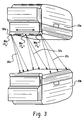
- the radiation source 30a contains a radioactive point source 36a adjustably mounted inside a shielded steel cylinder which is sealed at the ends. As shown in FIGURE 3, the radiation source 30a rasters longitudinally across the field of view as the gantry rotates through a plurality of angular orientations about the subject receiving aperture.
- the steel cylinder is adjustably mounted onto the corresponding detector head through a pivoting arm mechanism.
- the radiation source 30a is a bar source, flat rectangular source, disk source, flood source, tube or vessel filled with radionuclides, or active radiation generators such as x-ray tubes.
- a gantry rotation sensor 52 senses or indexes the gantry rotation, and therefore the location of the detector heads 20a-20c and the radiation source 30a at each data sampling.
- the gantry rotation sensor is an optical sensor which senses the position of the gantry versus time by projecting light, such as a laser beam, through a graticulated ring on the gantry and receiving the projected light. It is to be appreciated that conventional mechanical means, such as rotating gears, are also employed for detecting angular orientation of the gantry.
- a raster sensor 56 senses or indexes the location or speed of the point source 36a within the radiation source 30a as it continuously rasters back and forth across the field of view during the continuous rotation of the gantry 16 .
- data from the gantry sensor 52 and the raster sensor 56 are used to reconstruct the transmission data from the gantry sensor 56 and detector head. Radial and any circumferential offset information are used to reconstruct the emission data.
- Running an imaging operation includes a reconstruction process for emission and transmission data.
- the reconstruction process changes according to the type of radiation collected and the types of collimators used (i.e., fan, cone, parallel beam, and/or other modes).
- Emission radiation from the subject 12 is received by detector heads 20a-20c and transmission radiation 32a from the radiation source 30a is received by the detector head 20b to generate emission projection data and transmission projection data.
- the emission data normally contains inaccuracies caused by varying absorption characteristics of the subject's anatomy.
- a sorter 60 sorts the emission projection data and transmission projection data, such as on the basis of their relative energies or the detector head which originated the data.
- the data is stored in a projection view memory 62 , more specifically in a corresponding emission data memory 62e and transmission data memory 62t .
- a reconstruction processor 64t uses a fan beam reconstruction algorithm to reconstruct the transmission data into a transmission image representation or volume of attenuation factors stored in a memory 66 .
- Each voxel value stored in the memory 66 is indicative of attenuation of tissue in a corresponding location within the subject 12 .
- An emission data correction processor 68 corrects each emission data in accordance with the attenuation factors determined from the transmission data. More specifically, for each ray along which emission data is received, the emission correction processor 68 calculates a corresponding ray through the transmission attenuation factors stored in the memory 66 . Each ray of the emission data is then weighted or corrected by the emission data correction processor 68 in accordance with the attenuation factors. The corrected emission data are reconstructed by an emission radiation reconstruction processor 70 to generate a three-dimensional emission image representation that is stored in a volumetric emission image memory 72 . A video processor 74 withdraws selected portions of the data from the image memory 72 to generate corresponding human-readable displays on a video monitor 76 . Typical displays include reprojections, selected slices or planes, surface renderings, and the like.
- a continuous rotation sampling scheme is utilized to acquire transmission data.
- the point source continuously rasters back and forth across the field of view (from P a to P b and vice versa) while the gantry continuously rotates through a plurality of angular orientations to acquire transmission data.
- the gantry rotates continuously from 0° through 6° while the radiation point source rasters from P a 1 to P b 1,2 .
- Collecting transmission data during continuous rotation of the gantry facilitates sequential collection of a complete set of emission and transmission data in a greatly reduced time (as opposed to the step-and-shoot prior art method illustrated in FIGURE 4).
- each transmission projection is no longer a common horizontal line on a plot of gantry angle versus radiation source position and P b 1 and P b 2 completely overlap, illustrated as P b 1,2 in FIGURE 5.
- the transmission data is handled as a series of slices, each slice being defined by a plurality of radiation fans with known apices, each offset by a small angle from the preceding slice.
- the transmission reconstruction processor 64t uses a fan beam reconstruction algorithm which is indexed for the actual apex position of each sampled data line. It is to be appreciated that other conventional reconstruction algorithms may be employed. Proper indexing of the continuously changing camera geometry includes calculating an angular displacement versus radiation source motion index. This index relates the rate of gantry rotation to the rastering speed of the point source for any given element of a transmission projection.
- the gantry rotation sensor 52 senses the angular position of the gantry, and therefore the point source about the subject receiving aperture, while the raster speed sensor 56 senses the rastering position or speed of the point source.
- a simple division of gantry rotation speed (degree/second) by point source rastering speed (cm/second) can supply an angular displacement versus radiation source motion index (degree/cm) for use in the reconstruction algorithm.
- the motion index is converted into units of gantry rotation (in degrees) per unit of radiation source motion (in terms of a radiation detector face pixel). Therefore, the transmission reconstruction processor 64t updates the geometry of the gamma camera on a pixel-by-pixel basis.
- the effective resolution of the emission data is selected with the rotational speed of the rotating gantry.
- the effective transmission data resolution in the center plane is 6° and at the edge planes is 12°.
- the more significant portions of the image are normally near the center.
- two radiation sources are employed for transmission scanning with the angular sampling of the first source/detector combination overlapping the angular sampling of the second source/detector combination.
- the apex of the transmission radiation fan from the first source/detector combination is forced between the apex from the second source/detector combination such that the transmission data resolution is 6° at the edge planes, as in the center plane, resulting in better overall angular sampling.
- the resolution of the transmission data is adjustable by selecting the point source speed relative to the gantry rotation speed.
- the point source of radiation is preferably slow enough that a statistically meaningful amount of radiation is sampled in each plane, but fast enough that radiation fan apex orientation blurring is minimized.
Landscapes
- Physics & Mathematics (AREA)
- Health & Medical Sciences (AREA)
- Engineering & Computer Science (AREA)
- Biomedical Technology (AREA)
- General Health & Medical Sciences (AREA)
- Medical Informatics (AREA)
- Nuclear Medicine, Radiotherapy & Molecular Imaging (AREA)
- Optics & Photonics (AREA)
- Life Sciences & Earth Sciences (AREA)
- General Physics & Mathematics (AREA)
- High Energy & Nuclear Physics (AREA)
- Molecular Biology (AREA)
- Spectroscopy & Molecular Physics (AREA)
- Nuclear Medicine (AREA)
- Image Processing (AREA)
- Image Analysis (AREA)
Applications Claiming Priority (2)
| Application Number | Priority Date | Filing Date | Title |
|---|---|---|---|
| US09/522,737 US6429433B1 (en) | 2000-03-10 | 2000-03-10 | Continuous rotation sampling scheme for transmission radiation corrected gamma cameras |
| US522737 | 2000-03-10 |
Publications (2)
| Publication Number | Publication Date |
|---|---|
| EP1132756A2 true EP1132756A2 (fr) | 2001-09-12 |
| EP1132756A3 EP1132756A3 (fr) | 2004-01-28 |
Family
ID=24082114
Family Applications (1)
| Application Number | Title | Priority Date | Filing Date |
|---|---|---|---|
| EP01302241A Withdrawn EP1132756A3 (fr) | 2000-03-10 | 2001-03-12 | Gamma-caméras avec corrections pour la radiation transmise |
Country Status (3)
| Country | Link |
|---|---|
| US (1) | US6429433B1 (fr) |
| EP (1) | EP1132756A3 (fr) |
| JP (1) | JP2001324570A (fr) |
Cited By (3)
| Publication number | Priority date | Publication date | Assignee | Title |
|---|---|---|---|---|
| EP1921467A4 (fr) * | 2005-07-29 | 2012-09-26 | Japan Health Science Found | Tomographe, tomographie, programme de tomographie et support d enregistrement lisible par ordinateur sur lequel le programme est enregistré |
| US10126438B2 (en) | 2014-09-19 | 2018-11-13 | University Of Virginia Patent Foundation | Systems and methods for polarized nuclear imaging and spectroscopy |
| US11754652B2 (en) | 2016-09-15 | 2023-09-12 | University Of Virginia Patent Foundation | Systems and methods for polarized nuclear imaging and spectroscopy |
Families Citing this family (14)
| Publication number | Priority date | Publication date | Assignee | Title |
|---|---|---|---|---|
| EP1208390A4 (fr) * | 1999-06-06 | 2003-10-08 | Elgems Ltd | Camera gamma et systeme de tomographie assiste par ordinateur |
| US6878941B2 (en) * | 2002-04-09 | 2005-04-12 | Elgems Ltd. | Gamma camera and CT system |
| US20040217292A1 (en) * | 2003-05-01 | 2004-11-04 | Cti Pet Systems, Inc. | PET tomograph having continuously rotating panel detectors |
| US7397893B2 (en) * | 2004-09-27 | 2008-07-08 | Siemens Medical Solutions Usa, Inc. | Method and apparatus for simultaneous emission and transmission spect using oblique line sources |
| US8521251B2 (en) * | 2004-10-11 | 2013-08-27 | General Electric Company | Method and system for providing a noise based scan control |
| US7324624B2 (en) * | 2005-10-14 | 2008-01-29 | Siemens Medical Solutions Usa, Inc. | Shifted transmission mock for nuclear medical imaging |
| WO2009147607A2 (fr) * | 2008-06-06 | 2009-12-10 | Koninklijke Philips Electronics, N.V. | Procede et appareil de correction d’attenuation |
| JP2009058528A (ja) * | 2008-12-01 | 2009-03-19 | Hitachi Ltd | 放射線検査装置 |
| US9171079B2 (en) | 2011-01-28 | 2015-10-27 | Cisco Technology, Inc. | Searching sensor data |
| US9275093B2 (en) | 2011-01-28 | 2016-03-01 | Cisco Technology, Inc. | Indexing sensor data |
| US9225793B2 (en) * | 2011-01-28 | 2015-12-29 | Cisco Technology, Inc. | Aggregating sensor data |
| US20150065869A1 (en) * | 2013-09-03 | 2015-03-05 | Prescient Imaging LLC | Low noise transmission scan simultaneous with positron emission tomography |
| JP6720229B2 (ja) | 2015-07-09 | 2020-07-08 | コーニンクレッカ フィリップス エヌ ヴェKoninklijke Philips N.V. | 積層検出器を用いる同時x線及びガンマ光子イメージングのためのデバイス及び方法 |
| CN119247441A (zh) * | 2018-09-07 | 2025-01-03 | 深圳帧观德芯科技有限公司 | 成像系统和成像方法 |
Family Cites Families (7)
| Publication number | Priority date | Publication date | Assignee | Title |
|---|---|---|---|---|
| JP3168824B2 (ja) * | 1994-04-30 | 2001-05-21 | 株式会社島津製作所 | X線ct装置 |
| US5600145A (en) | 1995-01-19 | 1997-02-04 | Picker International, Inc. | Emission/transmission device for use with a dual head nuclear medicine gamma camera with the transmission source located behind the emission collimator |
| US5761333A (en) * | 1995-01-31 | 1998-06-02 | General Electric Company | Contrast enhancement for CT systems |
| US5552606A (en) * | 1995-05-11 | 1996-09-03 | Adac Laboratories, Inc. | Variable filters used with radiation source to reduce unobstructed detector area |
| US5638817A (en) | 1995-06-07 | 1997-06-17 | Picker International, Inc. | Gamma camera split collimator collimation method and apparatus |
| US5576545A (en) * | 1995-06-16 | 1996-11-19 | Siemens Medical Systems, Inc. | Line source for attenuation correction in nuclear medicine studies and apparatus and methods for using the source |
| US5717212A (en) | 1996-04-25 | 1998-02-10 | Picker International, Inc. | Three detector head gamma camera system with independently circumferentially positionable detector heads |
-
2000
- 2000-03-10 US US09/522,737 patent/US6429433B1/en not_active Expired - Fee Related
-
2001
- 2001-03-12 JP JP2001069272A patent/JP2001324570A/ja active Pending
- 2001-03-12 EP EP01302241A patent/EP1132756A3/fr not_active Withdrawn
Cited By (3)
| Publication number | Priority date | Publication date | Assignee | Title |
|---|---|---|---|---|
| EP1921467A4 (fr) * | 2005-07-29 | 2012-09-26 | Japan Health Science Found | Tomographe, tomographie, programme de tomographie et support d enregistrement lisible par ordinateur sur lequel le programme est enregistré |
| US10126438B2 (en) | 2014-09-19 | 2018-11-13 | University Of Virginia Patent Foundation | Systems and methods for polarized nuclear imaging and spectroscopy |
| US11754652B2 (en) | 2016-09-15 | 2023-09-12 | University Of Virginia Patent Foundation | Systems and methods for polarized nuclear imaging and spectroscopy |
Also Published As
| Publication number | Publication date |
|---|---|
| JP2001324570A (ja) | 2001-11-22 |
| EP1132756A3 (fr) | 2004-01-28 |
| US6429433B1 (en) | 2002-08-06 |
Similar Documents
| Publication | Publication Date | Title |
|---|---|---|
| US6388244B1 (en) | Virtual contouring for transmission scanning in spect and pet studies | |
| US6670614B1 (en) | Volume cone beam acquisition on a nuclear spect system using a digital flat panel | |
| US5210421A (en) | Simultaneous transmission and emission converging tomography | |
| US6787777B1 (en) | Nuclear imaging system and method using segmented field of view | |
| US6628983B1 (en) | Nuclear imaging systems and methods with feature-enhanced transmission imaging | |
| US5338936A (en) | Simultaneous transmission and emission converging tomography | |
| US5600145A (en) | Emission/transmission device for use with a dual head nuclear medicine gamma camera with the transmission source located behind the emission collimator | |
| US6211523B1 (en) | Autocontouring device for gamma camera using radioactive source and transverse motion | |
| EP0887661B1 (fr) | Imagerie diagnostique | |
| US6661865B1 (en) | Variable axial shielding for pet imaging | |
| US6429433B1 (en) | Continuous rotation sampling scheme for transmission radiation corrected gamma cameras | |
| US5818050A (en) | Collimator-free photon tomography | |
| Knoll | Single-photon emission computed tomography | |
| US6040580A (en) | Method and apparatus for forming multi-dimensional attenuation correction data in tomography applications | |
| US6201247B1 (en) | Line source for gamma camera | |
| WO1994009383A1 (fr) | Systeme d'imagerie par emission/transmission utilisant des donnees de transmission d'energie simple et d'energie double et d'emission de radionuclides | |
| US6171243B1 (en) | Combination of collimated and coincidence information for positron imaging | |
| EP1132757B1 (fr) | Gamma-caméras avec corrections pour la radiation transmise | |
| US7323689B2 (en) | Attenuation correction in nuclear medicine studies by simultaneous transmission and emission data measurement and estimation of emission-to-transmission crosstalk | |
| JP3881403B2 (ja) | 核医学診断装置 | |
| EP0969293B1 (fr) | Appareil photographique nucléaire utilisant des radio-isotopes | |
| Zoltani et al. | Flash x‐ray computed tomography facility for microsecond events | |
| JP4371636B2 (ja) | 核医学診断装置 | |
| JPH09236665A (ja) | 放射線診断装置 |
Legal Events
| Date | Code | Title | Description |
|---|---|---|---|
| PUAI | Public reference made under article 153(3) epc to a published international application that has entered the european phase |
Free format text: ORIGINAL CODE: 0009012 |
|
| AK | Designated contracting states |
Kind code of ref document: A2 Designated state(s): AT BE CH CY DE DK ES FI FR GB GR IE IT LI LU MC NL PT SE TR |
|
| AX | Request for extension of the european patent |
Free format text: AL;LT;LV;MK;RO;SI |
|
| RAP1 | Party data changed (applicant data changed or rights of an application transferred) |
Owner name: PHILIPS MEDICAL SYSTEMS (CLEVELAND), INC. |
|
| RAP1 | Party data changed (applicant data changed or rights of an application transferred) |
Owner name: KONINKLIJKE PHILIPS ELECTRONICS N.V. |
|
| PUAL | Search report despatched |
Free format text: ORIGINAL CODE: 0009013 |
|
| AK | Designated contracting states |
Kind code of ref document: A3 Designated state(s): AT BE CH CY DE DK ES FI FR GB GR IE IT LI LU MC NL PT SE TR |
|
| AX | Request for extension of the european patent |
Extension state: AL LT LV MK RO SI |
|
| RIC1 | Information provided on ipc code assigned before grant |
Ipc: 7G 01T 1/164 B Ipc: 7G 01T 1/29 A |
|
| 17P | Request for examination filed |
Effective date: 20040728 |
|
| AKX | Designation fees paid |
Designated state(s): AT BE CH CY DE DK ES FI FR GB GR IE IT LI LU MC NL PT SE TR |
|
| STAA | Information on the status of an ep patent application or granted ep patent |
Free format text: STATUS: THE APPLICATION HAS BEEN WITHDRAWN |
|
| 18W | Application withdrawn |
Effective date: 20070731 |