EP1132855A2 - Eingabevorrichtung und tragbares elektronisches Gerät dafür - Google Patents
Eingabevorrichtung und tragbares elektronisches Gerät dafür Download PDFInfo
- Publication number
- EP1132855A2 EP1132855A2 EP01301998A EP01301998A EP1132855A2 EP 1132855 A2 EP1132855 A2 EP 1132855A2 EP 01301998 A EP01301998 A EP 01301998A EP 01301998 A EP01301998 A EP 01301998A EP 1132855 A2 EP1132855 A2 EP 1132855A2
- Authority
- EP
- European Patent Office
- Prior art keywords
- operating
- operating member
- rotary electric
- electric part
- rotor
- Prior art date
- Legal status (The legal status is an assumption and is not a legal conclusion. Google has not performed a legal analysis and makes no representation as to the accuracy of the status listed.)
- Withdrawn
Links
Images


Classifications
-
- G—PHYSICS
- G06—COMPUTING OR CALCULATING; COUNTING
- G06F—ELECTRIC DIGITAL DATA PROCESSING
- G06F3/00—Input arrangements for transferring data to be processed into a form capable of being handled by the computer; Output arrangements for transferring data from processing unit to output unit, e.g. interface arrangements
- G06F3/01—Input arrangements or combined input and output arrangements for interaction between user and computer
- G06F3/03—Arrangements for converting the position or the displacement of a member into a coded form
- G06F3/033—Pointing devices displaced or positioned by the user, e.g. mice, trackballs, pens or joysticks; Accessories therefor
- G06F3/0362—Pointing devices displaced or positioned by the user, e.g. mice, trackballs, pens or joysticks; Accessories therefor with detection of one-dimensional [1D] translations or rotations of an operating part of the device, e.g. scroll wheels, sliders, knobs, rollers or belts
-
- H—ELECTRICITY
- H01—ELECTRIC ELEMENTS
- H01H—ELECTRIC SWITCHES; RELAYS; SELECTORS; EMERGENCY PROTECTIVE DEVICES
- H01H19/00—Switches operated by an operating part which is rotatable about a longitudinal axis thereof and which is acted upon directly by a solid body external to the switch, e.g. by a hand
- H01H19/02—Details
- H01H19/10—Movable parts; Contacts mounted thereon
- H01H19/14—Operating parts, e.g. turn knob
- H01H2019/146—Roller type actuators
Definitions
- the present invention relates to an input device for use in a portable electronic device such as a portable telephone set, as well as a portable electronic device using the input device.
- a rotary electric part 50 is constituted by a rotary encoder, and an insulating base 51 formed by molding a synthetic resin and constituting the rotary electric part 50, is provided with a substrate portion 51b having a central circular hole 51a, with plural contact pieces 52 being embedded in the substrate portion 51b.
- a rotor 54 of the rotary electric part 50 which rotor is formed by molding a synthetic resin, is provided with a disc portion 54a, shaft portions 54b and 54c projecting from both sides of the disc portion 54a, and a hexagonal, non-circular through hole 54d formed in a central part of the rotor 54.
- Code patterns 55 are formed on a surface of the disc portion 54a.
- the conventional input device has a push-switch 56.
- the push-switch 56 is provided with a housing 56a formed by molding a synthetic resin and with a contact portion (not shown) housed therein and is also provided with a push-button 56b attached to the housing 56a movably.
- the push-switch 56 is mounted to the printed circuit board P2 in a predetermined spaced position from the rotary electric part 50.
- An operating member 57 is provided with an operating portion 57a of a large diameter, shafts 57b and 57c projecting from both sides of the operating portion 57a, and a regular hexagonal sphere portion 57d formed at one end of the shaft 57b.
- the conventional input device since one rotary electric part 51 and the push-switch 56 are operated by one operating member 57, the number of functions available is small and thus the conventional input device is unsuitable for a portable electronic device for which various functions are required and is not convenient for use.
- an input device comprising a first operating member for operating a first rotary electric part, the first operating member being rotatable, and a second operating member for operating a second rotary electric part, the second operating member being also rotatable, the first and second operating members being each provided, on an outer peripheral portion in an axial direction thereof, with an operating portion for performing an operation in a direction orthogonal to the axial direction, the first and second operating members being disposed so as to be positioned close to each other in one and the same plane and so that the respective axial directions are orthogonal to each other.
- the first and second operating members are arranged in L shape.
- one of the first and second operating members can tilt with the associated first or second rotary electric part as fulcrum when pushed in a direction perpendicular to the axial direction thereof, and a push-switch is operated by the tilting motion.
- a portable electronic device comprising a case having a display in a front wall thereof, a first operating member for operating a first rotary electric part disposed within the case, the first operating member being rotatable, and a second operating member for operating a second rotary electric part disposed within the case, the second operating member being also rotatable, the first and second operating members being each provided, on an outer peripheral portion in an axial direction thereof, with an operating portion for performing an operation in a direction orthogonal to the axial direction, the first and second operating members being disposed so as to be positioned close to each other in one and the same plane, allowing the respective operating portions to be partially exposed from the front wall of the case, and so that the respective axial directions are orthogonal to each other.
- the first and second operating members are arranged in L shape.
- one of the first and second operating members can tilt with the rotary electric part as fulcrum when pushed in a direction perpendicular to the axial direction thereof, and a push-switch is operated by the tilting motion.
- both the first and second operating members can tilt with the rotary electric part as fulcrum when pushed in directions perpendicular to the respective axial directions, and a push-switch is operated by the tilting motion.
- an input device comprising a first rotary electric part having a rotor, a first operating member for operating the first rotary electric part, the first operating member having a first shaft fitted in a non-circular hole formed in the rotor of the first rotary electric part, a second rotary electric part having a rotor, and a second operating member for operating the second rotary electric part, the second operating member having a second shaft fitted in a non-circular hole formed in the rotor of the second rotary electric part, the first and second operating members being positioned in alignment with each other.
- the first operating member is further provided with an operating portion and a third shaft
- the second operating member is further provided with an operating portion and a fourth shaft, the third and fourth shafts being located respectively on the sides opposite to the first and second shafts with respect to the operating portions and in proximity to each other.
- one push-switch is disposed below the third and fourth shafts so as to straddle both shafts, the first or the second operating member tilts when pushed in a direction perpendicular to its axial direction, and the push-switch is operated thereby.
- a portable electronic device having an input device, the input device comprising a first rotary electric part having a rotor, a first operating member for operating the first rotary electric part, the first operating member having a first shaft fitted in a non-circular hole formed in the rotor of the first rotary electric part, a second rotary electric part having a rotor, and a second operating member for operating the second rotary electric part, the second operating member having a second shaft fitted in a non-circular hole formed in the rotor of the second rotary electric part, the first and second operating members being positioned in alignment with each other.
- the rotary electric part D used in this embodiment is formed as a rotary encoder.
- An insulating base 1, which is formed by molding an insulating material, is made up of a rectangular main base portion 2, a side wall portion 3 which is upright at right angles from the main base portion 2, and a pair of sub-base portions 5 connected respectively both sides of the main base portion 2 through thin-walled portions 4.
- the main base portion 2 is provided with recesses 2a formed respectively in end faces on both sides, a cylindrical protrusion 2b formed centrally on a front end face, and a pair of retaining portions 2c formed on a lower surface of the main base portion and each having a tapered portion.
- the side wall portion 3 is formed upright from corners of an upper surface of the main base portion 2.
- the side wall portion 3 is provided with a central circular hole 3b having a flange 3a, a pair of relief holes 3c extending from both sides of the hole 3b up to the main base portion 2, a pair of upper walls 3d extending perpendicularly from an upper position, a groove 3e formed between the paired upper walls 3d, retaining portions 3f formed respectively on upper surfaces of the paired upper walls 3d, and protrusions 3g.
- Each of the paired sub-base portions 5 is provided with a convex portion 5a formed on an end face and having a roundish end.
- a plurality of contact pieces 6 each formed by a metallic plate are each provided with a contact portion 6a and a terminal portion 6b.
- the contact pieces 6 are respectively embedded in the sub-base portions 5.
- the contact portion 6a projects upward from an upper surface of the insulating base 1, while the terminal portion 6b projects downward from a lower surface of the insulating base 1 and a flat surface of an outer end thereof is bent so as to be positioned in parallel with and at substantially the same position as one end of the insulating base 1, i.e., the side wall portion 3.
- the common contact piece 7 is embedded in the main base portion 2 at a position close to the side wall portion 3.
- the contact portions 7a project upward from the upper surface of the insulating base 1 and are positioned in the relief holes 3c of the side wall portion 3, while the terminal portion 7b projects downward from the lower surface of the insulating base 1.
- each embedded contact piece 6 straddles the main base portion 2 and the associated sub-base portion 5 and constitutes each thin-walled portion 4 as a connection between the main and sub-base portions 2, 5.
- a metallic plate separate from that of the contact piece 6 may be embedded in the insulating base 1 to form each thin-walled portion 4. Further, the thin-walled portion 4 may be formed by the insulating material of the insulating base 1.
- a cylindrical rotor 8 which is formed by molding an insulating material, comprises a shaft portion 8a provided on one end side, a holding portion 8b formed contiguously to the shaft portion 8a and having a diameter larger than the diameter of the shaft portion 8a, a concave-convex portion 8d for clicking which is formed on an end face 8c on one side of the holding portion 8b which end face is orthogonal to a rotational axis direction of the rotor, and end face 8e positioned between the shaft portion 8a and the holding portion 8b on an opposite side of the holding portion, the end face 8e being orthogonal to the rotational axis direction of the rotor, and a non-circular, hexagonal hole 8f formed centrally.
- a code member 9 which is formed by a metallic plate, is provided with a ring-like plate portion 9a which forms a common pattern and a plurality of tongue pieces 9b which are bent from an inner periphery of the plate portion 9a and which form code patterns, as shown particularly in Fig. 11.
- the code member 9 is embedded or press-fitted into the rotor 8.
- the ring-like plate portion 9a which forms a common pattern is positioned at the end face 8e of the rotor 8, while the tongue pieces 9b which form a code pattern are exposed to an outer circumferential surface of the holding portion 8b.
- the tongue pieces 9b extend in an axial direction G1 of the rotor 8.
- the shaft portion 8a is fitted in the hole 3b loosely so as to create a small clearance K1, thereby permitting the rotor 8 to perform a tilting motion with respect to the insulating base 1.
- the paired contact portions 7a of the common contact piece 7 are opposed to the end face 8e and are in contact with the plate portion 9a as a common pattern of the code member 9.
- the plural contact pieces 6 are positioned on opposite sides with the circumferential surface of the rotor therebetween and come into and out of contact with the tongue pieces 9b as code patterns of the code member 9, and a pair of contact portions 6a are brought into contact with the code patterns with a phase difference.
- the contact pieces 6 are located perpendicularly to the axial direction G1 and are put in sliding contact with the code patterns.
- An engaging member 10 which is formed by a metallic plate, comprises a rectangular plate-like base portion 10a, an engaging portion 10b formed by cutting and bending a central part of the base portion 10 in a C shape, the engaging portion 10b having convex portions at free ends thereof, a circular hole 10c formed in a lower position of the base portion 10a, a pair of side plates 10d bent from both sides of the base portion 10a, cut and raised portions 10e formed in the side plates 10d respectively, a T-shaped upper-side plate 10g bent from an upper side of the base portion 10a and having a retaining portion 10f at a free end thereof, and a C-shaped lower-side plate 10j bent from a lower side of the base portion 10a and having a rectangular hole 10h formed centrally.
- the engaging member 10 is aligned with the insulating base 1 so that the engaging portion 10b becomes opposed to the end face 8c of the rotor 8 having the concave-convex portion 8d, and then the protrusion 2b is inserted into the hole 10c.
- the upper-side plate 10g is positioned on the upper walls 3d of the side wall portion 3 and is pushed in, allowing the retaining portion 10f to be engaged with the retaining portions 3f. Further, the upper-side plate 10g is positioned in the groove 3e and is secured to the side wall portion 3.
- the lower-side plate 10j is positioned on the lower surface of the main base portion 2 and is pushed in, allowing the retaining portions 2c to be positioned in the hole 10h, whereby the lower-side plate 10j is locked to the retaining portions 2c and the lower-side plate 10j is secured to the main base portion 2.
- the engaging member 10 is mounted at both upper and lower positions relative to the rotor 8, while the side plates 10d are located at right and left positions respectively relative to the rotor 8.
- the convex portions of the engaging portion 10b are engaged disengageably with the concave-convex portion 8d formed on the end face 8c of the rotor 8, constituting a click mechanism.
- the engaging member 10, the contact pieces 6 and the common contact piece 7 extend toward the rotor 8 with the insulating base 1 as a reference plane.
- An encoder body E1 is formed by such a configuration.
- a mounting plate 12 which is constituted by a solderable metallic plate, comprises a flat plate portion 12c, the flat plate portion 12c having a cylindrical portion 12h formed with a large circular hole 12a centrally and also having a small hole 12b in a lower position, a pair of arm portions 12d bent opposedly from both sides of the flat plate portion 12c, rectangular holes 12e formed centrally of the arm portions 12d respectively, mounting portions 12f bent from side ends of the arm portions 12d, and projecting portions 12g provided on the mounting portions 12f side of the flat plate portion 12c.
- the mounting plate 12 is positioned on the engaging member 10 side of the encoder body E1 and the cylindrical portion 12h is positioned within the rotor 8, then in this state the protrusion 2b of the insulating base 1 is inserted into the small hole 12b.
- the arm portions are pushed inwards on the side plates 10d of the engaging member 10, so that the cut and raised portions 10e are positioned in the holes 12e respectively and the arm portions 12d are engaged with the cut and raised portions 10e, whereby the mounting plate 12 is snap-fastened to the engaging member 10.
- the mounting plate 12 When the mounting plate 12 is thus mounted, the flat plate portion 12c is superimposed outside the plate-like base portion 10a of the engaging member 10, the arm portions 12d are mounted to the side plate 10d respectively at right and left positions with respect to the rotor 8.Lower surfaces of the mounting portions 12f bent from side ends of the arm portions 12d which extend in the axial direction G1 of the rotor 8 are located at approximately the same position as the L-shaped terminal portions 6b and 7b of the contact pieces 6 and the common contact piece 7 both extending from the lower surface of the insulating base 1.
- a clearance K2 is formed between the cylindrical portion 12h and the rotor 8, the clearance K2 being larger than the clearance K1.
- the rotor 8 is brought into abutment against the side wall portion 3 by the engaging member 10.
- the undersides of the main- and sub-base portions 2, 5 are brought into opposition to a printed circuit board P1 and the projecting portions 12g are inserted into holes 13 formed in the printed circuit board P1, whereby the rotary electric part D is established its position.
- the terminal portions 6b and 7b of the contact pieces 6 and the common contact piece 7, and the mounting portions 12f of the mounting plate 12 are positioned on wiring patterns (not shown) formed on an upper surface of the printed circuit board P1.
- the contact pieces 6, the common contact piece 7 and the mounting plate 12 thus constituted are surface-mounted to the wiring patterns by creamy solder and thus mounted to the printed circuit board P1, whereby the rotary electric part D is mounted to the printed circuit board in parallel with the axial direction G1 of the rotor 8.
- the concave-convex portion 8d of the rotor 8 performs engaging and disengaging motions for the engaging portion 10b to effect a click motion, the tongue pieces 9b come into and out of contact with the contact pieces 6, and the common contact piece 7 contacts the plate portion 9a constantly, with consequent generation of a two-phase pulse signal between the contact pieces 6 and the common contact piece 7.
- first and second rotary electric parts D1, D2, as the rotary electric part D constituted as above, are mounted to the printed circuit board P1 spacedly in alignment with each other through mounting plates 12 which are opposed to each other, as shown in Fig. 1.
- a push-switch 15 is made up of a housing 16 which houses a contact portion (not shown) therein and a push-button 17 which is secured to the housing 16 vertically movably and which is urged upwards constantly.
- the push-switch 15 is mounted to the printed circuit board P1 at a position intermediate between the first and second rotary electric parts D1, D2 and on an extension of the axial direction G1.
- First and second operating members 18, which are formed by molding a synthetic resin, each comprise a cylindrical operating portion 18a of a large diameter, a first cylindrical shaft 18c and a third cylindrical shaft 18d (or a second cylindrical shaft 18c and a fourth cylindrical shaft 18d) smaller in diameter than the operating portion 18a, the shafts 18c and 18d projecting in an axial direction G2 of the operating member 18 from central positions of both side faces 18b of the operating portion 18a, and a hexagonal, non-cylindrical, non-circular portion 18e formed at an end portion of the first (or the second) shaft 18c.
- the first and second shafts 18c of the first and second operating members 18 are respectively inserted into the holes 12a from the mounting plates 12 side while being guided by the cylindrical portions 12h, and the non-circular portions 18e are fitted respectively in the non-circular holes 8f of the rotors 8.
- the third and fourth shafts 18d of the first and second operating members 18 are positioned close to each other and are simultaneously supported by the upper wall 19b.
- the tilting motion of the first operating member 18 is performed in the following manner.
- Fig. 2 when the operating member 18 is pushed, first a lower portion of the shaft 8a of the rotor 8 comes into abutment with the side face of the insulating base 1 which defines the hole 3b.
- the rotor 8 begins to tilt with an abutment portion T1 as fulcrum and at the same time the outermost periphery of the plate portion 9a of the code member 9 abuts the insulating base 1 at an abutment portion T2.
- the rotor 8 tilts at a predetermined angle A2 equal to that of the operating member 18 and the mounting plate 12-side portion of the rotor 8 moves to a greater extent than the insulating base 1-side portion thereof, but the presence of the large clearance K2 permits the tilting motion of the rotor 8.
- the code patterns (tongue pieces 9b) extending in the axial direction G1 and the contact pieces 6 disposed perpendicularly thereto are in contact with each other, provided the position of contact of the code patterns with the contact pieces 6 merely shifts downward, and therefore both are kept contacted positively.
- the tongue pieces are less displaced at their contact portions with the contact pieces 6, thus making it difficult to produce unnecessary pulse signals.
- the third shaft 18d is guided by a vertical groove (not shown) formed in the case 19 and thus its downward movement can be done accurately.
- the operation for rotation and tilting of the second operating member 18 is the same as that for the first operating member 18 described above, so an explanation thereof will here be omitted.
- the input device of this embodiment is operated in the manner described above.
- a vertical scrolling operation is performed by the first electric device D1 through the first operating member 18 and a decision operation is performed by the push-switch 15, while a transverse scrolling operation is performed by the second electric part D2 through the second operating member 18 and a decision operation is performed by the push-switch 15.
- a multi-functional operation can be effected.
- first and second operating members 18 are aligned with each other, the above operations can be done by putting one finger of one hand on the first operating member and putting another finger on the second operating member and then moving the fingers.
- the tilting motion of the rotor 8 is conducted with the insulating base 1 as a support member
- the mounting plate 12 or another member may be used as the support member.
- a rotary electric part D used in this embodiment it is of the same configuration as that described above and so an explanation thereof will here be omitted, and the same components as in the input device of the previous first embodiment will be identified by the same reference numerals as in the first embodiment.
- a push-switch 15 is made up of a housing 16 which houses a contact portion (not shown) therein and a push-button 17 which is secured to the housing 16 vertically movably and which is urged upwards constantly.
- the push-switch 15 is mounted to the printed circuit board P1 on an extension of the axial direction G1 of the first rotary electric part D1.
- First and second operating members 18, which are formed by molding a synthetic resin, each comprise a cylindrical operating portion 18a of a large diameter, a first cylindrical shaft 18c and a third cylindrical shaft 18d (or a second cylindrical shaft 18c and a fourth cylindrical shaft 18d) smaller in diameter than the operating portion 18a, the shafts 18c and 18d projecting in an axial direction G2 of the operating member 18 from central positions of both side faces 18b of the operating portion 18a, a hexagonal, non-cylindrical, non-circular portion 18e formed at an end portion of the first (or the second) shaft 18c, and a knurled portion 18g formed on the surface of the operating portion 18a.
- the knurled portion 18g is formed by a concave-convex portion in the axial direction G2, it may be a knurled portion other than such concave-convex portion.
- it may be a rough surface.
- the second operating member 18 may be shifted in the axial direction G2 from an intermediate portion of the first operating member 18 so that the first and second operating members 18 are arranged in L shape.
- a case 19 which is formed by molding a synthetic resin, comprises an upper wall 19b having two holes 19a formed in side positions of the T shape, side walls 19c extending downwards from the outer periphery of the upper wall 19b, and a partition wall 19d.
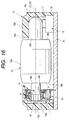
- the first operating member 18 tilts at a predetermined angle A1 on its third shaft 18d side with the first rotary electric part D1 as fulcrum, as shown in Fig. 17, with the result that the push-button 17 moves downward and the push-switch 15 is operated (contact ON to OFF or OFF to ON).
- the third shaft 18d is guided by a vertical groove (not shown) formed in the case 19 and thus its downward movement can be done accurately.
- the second operating member 18 when operated for rotation, it rotates while being supported by both the second rotary electric part D2 and the partition wall 19d. Its rotating motion is the same as in the case of the first operating member 18 described previously, so an explanation thereof will here be omitted.
- the input device of this embodiment is operated in this manner.
- a vertical scrolling operation is performed by the first electric part D1 through the first operating member 18 and a decision operation is performed by the push-switch 15, while a transverse scrolling operation is performed by the second electric part D2 through the second operating member 18 and a decision operation is performed by the push-switch 15, thus permitting a multi-functional operation to be effected.
- the tilting motion of the rotor 8 is performed with the insulating base 1 as a support member
- the mounting plate 12 or another member may be used as the support member.
- the second operating member 18 does not perform a tilting motion
- a case 20 which is formed by molding a synthetic resin and which is in the shape of a rectangular parallelepiped, comprises a front wall 20a, side walls 20b extending from four sides of the front wall 20a, and a back wall 20c opposite to the front wall 20a.
- Various electric parts (not shown) are accommodated within the case 20, and a display 21 is provided in an upper position of the front wall 20a.
- the input device of the above second embodiment is disposed within the case 20 at a position close to the display 21 and the operating portions 18a of the first and second operating members 18 are partially exposed from a hole (not shown) formed in the case 20.
- Plural push-buttons are disposed on the front wall 20a of the case 20 at positions below the input device.
- the case 19 may be substituted by the case 20.
- the input device of the above second embodiment is used in the portable electronic device, it may be substituted by the input device of the above first embodiment.
- the portable electronic device having such a configuration is operated in the same way as in the input device of the above second embodiment, which operation is performed while checking display contents on the display 21.
Landscapes
- Engineering & Computer Science (AREA)
- General Engineering & Computer Science (AREA)
- Theoretical Computer Science (AREA)
- Human Computer Interaction (AREA)
- Physics & Mathematics (AREA)
- General Physics & Mathematics (AREA)
- Switches With Compound Operations (AREA)
- Input From Keyboards Or The Like (AREA)
Applications Claiming Priority (4)
| Application Number | Priority Date | Filing Date | Title |
|---|---|---|---|
| JP2000072475 | 2000-03-10 | ||
| JP2000072475A JP2001255990A (ja) | 2000-03-10 | 2000-03-10 | 入力装置 |
| JP2000077823A JP2001265508A (ja) | 2000-03-15 | 2000-03-15 | 入力装置、及びこの入力装置を使用した携帯用電子機器 |
| JP2000077823 | 2000-03-15 |
Publications (2)
| Publication Number | Publication Date |
|---|---|
| EP1132855A2 true EP1132855A2 (de) | 2001-09-12 |
| EP1132855A3 EP1132855A3 (de) | 2005-11-02 |
Family
ID=26587585
Family Applications (1)
| Application Number | Title | Priority Date | Filing Date |
|---|---|---|---|
| EP01301998A Withdrawn EP1132855A3 (de) | 2000-03-10 | 2001-03-05 | Eingabevorrichtung und tragbares elektronisches Gerät dafür |
Country Status (2)
| Country | Link |
|---|---|
| US (1) | US20010023179A1 (de) |
| EP (1) | EP1132855A3 (de) |
Cited By (2)
| Publication number | Priority date | Publication date | Assignee | Title |
|---|---|---|---|---|
| EP1574938A2 (de) | 2004-03-10 | 2005-09-14 | Samsung Electronics Co., Ltd. | Schalteranordnung |
| DE102009005283A1 (de) * | 2009-01-21 | 2010-07-22 | Leopold Kostal Gmbh & Co. Kg | Druck- und drehbetätigbares Bedienelement für ein Kraftfahrzeug |
Family Cites Families (18)
| Publication number | Priority date | Publication date | Assignee | Title |
|---|---|---|---|---|
| DE8419546U1 (de) * | 1984-06-29 | 1984-10-31 | Stein, Norbert, 2000 Hamburg | Steuergerät für die Schreibmarke auf einem Computerbildschirm |
| DE3906585A1 (de) * | 1989-03-02 | 1990-09-06 | Thomson Brandt Gmbh | Fernbedieneinheit |
| US5095303A (en) * | 1990-03-27 | 1992-03-10 | Apple Computer, Inc. | Six degree of freedom graphic object controller |
| JPH04220710A (ja) * | 1990-12-21 | 1992-08-11 | Sharp Corp | 入力装置 |
| US5448240A (en) * | 1991-08-29 | 1995-09-05 | Alps Electric Co., Ltd. | Remote control input device |
| DE69634840T2 (de) * | 1995-08-23 | 2006-05-11 | Matsushita Electric Industrial Co., Ltd., Kadoma | Elektronisches Betätigungsbauteil |
| US5669485A (en) * | 1996-01-02 | 1997-09-23 | Motorola, Inc. | Rotary switch knob assembly with interspersed radial labeling |
| DE19643201B4 (de) * | 1996-10-19 | 2005-06-02 | Loewe Opta Gmbh | Fernbedienungsgeber |
| JPH10163953A (ja) * | 1996-11-29 | 1998-06-19 | Sony Corp | 情報入力装置およびカーソル移動装置、ならびに、これらを使用した携帯電話装置 |
| JP3437054B2 (ja) * | 1997-05-12 | 2003-08-18 | アルプス電気株式会社 | 多入力スイッチ |
| FR2767397B3 (fr) * | 1997-08-18 | 1999-07-23 | Kuo Shu Cheng | Dispositif d'entree de signal a axes multiples d'une souris |
| US6097964A (en) * | 1997-09-04 | 2000-08-01 | Nokia Mobile Phones Limited | Navigation key for a handset |
| GB2335822B (en) * | 1998-03-25 | 2003-09-10 | Nokia Mobile Phones Ltd | Context sensitive pop-up window for a portable phone |
| KR20000047803A (ko) * | 1998-12-04 | 2000-07-25 | 이데이 노부유끼 | 스위치 장치 |
| TW508606B (en) * | 1999-07-27 | 2002-11-01 | Alps Electric Co Ltd | Multi-directional input device |
| DE60001480T2 (de) * | 1999-12-10 | 2003-08-28 | Alps Electric Co., Ltd. | Winkelkodierer |
| JP3869996B2 (ja) * | 2000-03-10 | 2007-01-17 | アルプス電気株式会社 | 多方向入力装置 |
| JP2001312942A (ja) * | 2000-04-27 | 2001-11-09 | Sony Corp | 通信端末装置及びスイッチ装置 |
-
2001
- 2001-03-05 EP EP01301998A patent/EP1132855A3/de not_active Withdrawn
- 2001-03-09 US US09/803,568 patent/US20010023179A1/en not_active Abandoned
Cited By (3)
| Publication number | Priority date | Publication date | Assignee | Title |
|---|---|---|---|---|
| EP1574938A2 (de) | 2004-03-10 | 2005-09-14 | Samsung Electronics Co., Ltd. | Schalteranordnung |
| DE102009005283A1 (de) * | 2009-01-21 | 2010-07-22 | Leopold Kostal Gmbh & Co. Kg | Druck- und drehbetätigbares Bedienelement für ein Kraftfahrzeug |
| DE102009005283B4 (de) * | 2009-01-21 | 2021-06-17 | Kostal Automobil Elektrik Gmbh & Co. Kg | Druck- und drehbetätigbares Bedienelement für ein Kraftfahrzeug |
Also Published As
| Publication number | Publication date |
|---|---|
| EP1132855A3 (de) | 2005-11-02 |
| US20010023179A1 (en) | 2001-09-20 |
Similar Documents
| Publication | Publication Date | Title |
|---|---|---|
| JP4487821B2 (ja) | 複合操作型電子部品 | |
| JPH097462A (ja) | プッシュスイッチ付き回転操作型電子部品 | |
| EP1139273B1 (de) | Mehrrichtungseingabevorrichtung | |
| WO2005038844A1 (ja) | 回転・押圧操作型電子部品およびそれを用いた電子機器 | |
| JP2001325859A (ja) | 複合操作型スイッチ装置 | |
| JP3763711B2 (ja) | 複合操作型電子部品 | |
| JP2005158328A (ja) | 回転操作型電子部品 | |
| JP2002110002A (ja) | スイッチ装置 | |
| EP1132856A1 (de) | Eingabevorrichtung und tragbares elektronisches Gerät mit einer solchen Vorrichtung | |
| EP1132855A2 (de) | Eingabevorrichtung und tragbares elektronisches Gerät dafür | |
| JP4213019B2 (ja) | 多方向入力装置 | |
| JP2005259634A (ja) | 回転型電気部品 | |
| JP2001345031A (ja) | 複合操作型電子部品 | |
| WO2005038843A1 (ja) | 回転・押圧操作型電子部品およびそれを用いた電子機器 | |
| JP2001325860A (ja) | 複合操作型スイッチ装置 | |
| JP3770768B2 (ja) | 多方向入力装置 | |
| JP3937670B2 (ja) | 多方向操作スイッチ | |
| EP0918344A2 (de) | Schalter und Elektronisches Gerät die dieser Schalter verwendet | |
| JP2003217402A (ja) | 複合スイッチ | |
| JP2001332155A (ja) | 多方向入力装置 | |
| JP2001255990A (ja) | 入力装置 | |
| KR100298507B1 (ko) | 스위치 | |
| JP2001265508A (ja) | 入力装置、及びこの入力装置を使用した携帯用電子機器 | |
| JP3819677B2 (ja) | 入力装置 | |
| JP2024051281A (ja) | 動作位置可変マイクロリーフスイッチ並びに複合操作スイッチ |
Legal Events
| Date | Code | Title | Description |
|---|---|---|---|
| PUAI | Public reference made under article 153(3) epc to a published international application that has entered the european phase |
Free format text: ORIGINAL CODE: 0009012 |
|
| AK | Designated contracting states |
Kind code of ref document: A2 Designated state(s): AT BE CH CY DE DK ES FI FR GB GR IE IT LI LU MC NL PT SE TR |
|
| AX | Request for extension of the european patent |
Free format text: AL;LT;LV;MK;RO;SI |
|
| PUAL | Search report despatched |
Free format text: ORIGINAL CODE: 0009013 |
|
| AK | Designated contracting states |
Kind code of ref document: A3 Designated state(s): AT BE CH CY DE DK ES FI FR GB GR IE IT LI LU MC NL PT SE TR |
|
| AX | Request for extension of the european patent |
Extension state: AL LT LV MK RO SI |
|
| RIC1 | Information provided on ipc code assigned before grant |
Ipc: 7H 01H 25/00 B Ipc: 7G 06F 3/033 B Ipc: 7G 06K 11/18 A |
|
| AKX | Designation fees paid |
Designated state(s): DE FI FR GB SE |
|
| STAA | Information on the status of an ep patent application or granted ep patent |
Free format text: STATUS: THE APPLICATION IS DEEMED TO BE WITHDRAWN |
|
| 18D | Application deemed to be withdrawn |
Effective date: 20060503 |