EP1132933A2 - Verfahren zur Dateneingabe in einen elektronischen Apparat - Google Patents
Verfahren zur Dateneingabe in einen elektronischen Apparat Download PDFInfo
- Publication number
- EP1132933A2 EP1132933A2 EP01660037A EP01660037A EP1132933A2 EP 1132933 A2 EP1132933 A2 EP 1132933A2 EP 01660037 A EP01660037 A EP 01660037A EP 01660037 A EP01660037 A EP 01660037A EP 1132933 A2 EP1132933 A2 EP 1132933A2
- Authority
- EP
- European Patent Office
- Prior art keywords
- key code
- selector
- electronic device
- auxiliary device
- code
- Prior art date
- Legal status (The legal status is an assumption and is not a legal conclusion. Google has not performed a legal analysis and makes no representation as to the accuracy of the status listed.)
- Withdrawn
Links
Images



Classifications
-
- G—PHYSICS
- G07—CHECKING-DEVICES
- G07C—TIME OR ATTENDANCE REGISTERS; REGISTERING OR INDICATING THE WORKING OF MACHINES; GENERATING RANDOM NUMBERS; VOTING OR LOTTERY APPARATUS; ARRANGEMENTS, SYSTEMS OR APPARATUS FOR CHECKING NOT PROVIDED FOR ELSEWHERE
- G07C9/00—Individual registration on entry or exit
- G07C9/00174—Electronically operated locks; Circuits therefor; Nonmechanical keys therefor, e.g. passive or active electrical keys or other data carriers without mechanical keys
- G07C9/00658—Electronically operated locks; Circuits therefor; Nonmechanical keys therefor, e.g. passive or active electrical keys or other data carriers without mechanical keys operated by passive electrical keys
- G07C9/00666—Electronically operated locks; Circuits therefor; Nonmechanical keys therefor, e.g. passive or active electrical keys or other data carriers without mechanical keys operated by passive electrical keys with dials
-
- H—ELECTRICITY
- H01—ELECTRIC ELEMENTS
- H01H—ELECTRIC SWITCHES; RELAYS; SELECTORS; EMERGENCY PROTECTIVE DEVICES
- H01H19/00—Switches operated by an operating part which is rotatable about a longitudinal axis thereof and which is acted upon directly by a solid body external to the switch, e.g. by a hand
- H01H19/001—Thumb wheel switches
-
- H—ELECTRICITY
- H04—ELECTRIC COMMUNICATION TECHNIQUE
- H04M—TELEPHONIC COMMUNICATION
- H04M1/00—Substation equipment, e.g. for use by subscribers
- H04M1/66—Substation equipment, e.g. for use by subscribers with means for preventing unauthorised or fraudulent calling
- H04M1/667—Preventing unauthorised calls from a telephone set
- H04M1/67—Preventing unauthorised calls from a telephone set by electronic means
- H04M1/673—Preventing unauthorised calls from a telephone set by electronic means the user being required to key in a code
-
- H—ELECTRICITY
- H04—ELECTRIC COMMUNICATION TECHNIQUE
- H04W—WIRELESS COMMUNICATION NETWORKS
- H04W12/00—Security arrangements; Authentication; Protecting privacy or anonymity
- H04W12/50—Secure pairing of devices
-
- G—PHYSICS
- G07—CHECKING-DEVICES
- G07C—TIME OR ATTENDANCE REGISTERS; REGISTERING OR INDICATING THE WORKING OF MACHINES; GENERATING RANDOM NUMBERS; VOTING OR LOTTERY APPARATUS; ARRANGEMENTS, SYSTEMS OR APPARATUS FOR CHECKING NOT PROVIDED FOR ELSEWHERE
- G07C9/00—Individual registration on entry or exit
- G07C9/00174—Electronically operated locks; Circuits therefor; Nonmechanical keys therefor, e.g. passive or active electrical keys or other data carriers without mechanical keys
- G07C2009/00753—Electronically operated locks; Circuits therefor; Nonmechanical keys therefor, e.g. passive or active electrical keys or other data carriers without mechanical keys operated by active electrical keys
- G07C2009/00769—Electronically operated locks; Circuits therefor; Nonmechanical keys therefor, e.g. passive or active electrical keys or other data carriers without mechanical keys operated by active electrical keys with data transmission performed by wireless means
- G07C2009/00793—Electronically operated locks; Circuits therefor; Nonmechanical keys therefor, e.g. passive or active electrical keys or other data carriers without mechanical keys operated by active electrical keys with data transmission performed by wireless means by Hertzian waves
-
- H—ELECTRICITY
- H04—ELECTRIC COMMUNICATION TECHNIQUE
- H04M—TELEPHONIC COMMUNICATION
- H04M1/00—Substation equipment, e.g. for use by subscribers
- H04M1/72—Mobile telephones; Cordless telephones, i.e. devices for establishing wireless links to base stations without route selection
- H04M1/724—User interfaces specially adapted for cordless or mobile telephones
-
- H—ELECTRICITY
- H04—ELECTRIC COMMUNICATION TECHNIQUE
- H04M—TELEPHONIC COMMUNICATION
- H04M2250/00—Details of telephonic subscriber devices
- H04M2250/02—Details of telephonic subscriber devices including a Bluetooth® interface
-
- H—ELECTRICITY
- H04—ELECTRIC COMMUNICATION TECHNIQUE
- H04M—TELEPHONIC COMMUNICATION
- H04M2250/00—Details of telephonic subscriber devices
- H04M2250/14—Details of telephonic subscriber devices including a card reading device
Definitions
- the present invention relates to an electronic device as set forth in the preamble of the appended claim 1.
- the invention also relates to a method for entering a key code in an electronic device as set forth in the preamble of the appended claim 11.
- the invention relates to a wireless device and an auxiliary device as set forth in the reamble of the appended claim 19.
- Bluetooth is an open technology for data and audio transmission. It is based on short distance radio links which are implemented in small integrated circuits having e . g . a size of approximately 9 ⁇ 9 mm and containing a transceiver. The range of the devices is typically about ten metres, but by using a higher transmission level, it is possible to reach a range of even 100 m.
- the technology is intended for quick mobile communication between very different digital devices, wherein the maximum data transmission rate is approximately 1 Mb/s. These devices can be for example mobile phones, portable computers, various peripheral computer devices, PDA devices, cameras, and/or fax machines. Some of the devices can be portable devices and some can be stationary. Between these devices, the Bluetooth technology can set up a wireless data transmission link operating at a frequency of approximately 2.4 GHz. Furthermore, data security properties are implemented e . g . by 40-bit enciphering.
- Devices using the above-mentioned technology can set up connections both point-to-point and point-to-multi-point.
- the technology can be used to implement a so-called piconet which can comprise 2 to 8 devices.
- the security of the communication protocol is based on a complex key formation algorithm and an exchange protocol. This protocol first creates an authentication key which is generated from a secret key entered by the user, such as a PIN code (Personal Identification Number); furthermore, an encryption key is generated.
- PIN code Personal Identification Number
- an encryption key is generated.
- the communicating parties have checked each other's rights, after which a secure data transmission link has been set up between these parties. This process is called pairing. To make this pairing successful, the same secret key code must be entered in each device.
- the length of the key code in bit form can be 1 to 16 bytes, i.e. 8 to 128 bits.
- the alternatives for a one-byte key are the digits from 0 to 255
- the alternatives for a key of two bytes are 0 to 65,535
- the alternatives for a key of three bytes are 0 to 16,777,215, etc.
- the devices applying the Bluetooth technology are normally various auxiliary devices, such as a wireless portable hands-free set and a wireless smart card reader. It is common to the devices that they normally require a secure data transmission link and that they normally have very limited possibilities for user interaction. This is due to the fact that the devices are normally small and they have no display or keypad. For this reason, it is very difficult to enter a PIN code required by the protocol in these devices. On the other hand, if these devices were equipped with the means required for entering a PIN code, particularly a keypad and a display, which were used as a user interface, the device would be larger and more expensive. This is not desirable in devices of prior art which should be preferably inexpensive and small, because they are normally various portable devices and their auxiliary devices which should for example fit in a pocket.
- PIN code is installed in the Bluetooth device already in connection with the manufacture. Thus the user will never have to enter the PIN code to use this Bluetooth device. Also any third party can use this Bluetooth device, because it is not protected with a separate PIN code.
- the PIN code can also be transmitted to the Bluetooth device by means of the Bluetooth protocol. Even this solution is not very good, because a security risk still exists.
- This aim can be achieved by providing the device with at least one, for example a substantially wheel-like or a substantially disc-like rotatable selecting means whereby e.g. a PIN code can be entered.
- a substantially wheel-like or a substantially disc-like rotatable selecting means whereby e.g. a PIN code can be entered.
- the electronic device according to the invention is characterized in what will be presented in the characterizing part of claim 1.
- the method according to the invention is characterized in what will be presented in the characterizing part of claim 11.
- the wireless device and the auxiliary device according to the invention are characterized in what will be presented in the characterizing part of claim 19.
- the present invention provides significant advantages.
- the selecting means can be made compact without affecting its usability, wherein the need for space in the electronic device is correspondingly small. Furthermore, it is significantly more advantageous to implement one or more selecting means than in solutions of prior art.
- a secure and easy way to enter a secret key code can also be implemented in inexpensive, simple and/or compact, particularly mobile peripheral devices, in which no keypad is needed. Thus, any expensive and large keypad or possibly also a display is not needed in the device.
- Bluetooth technology and protocol are only used as an example of an application for which the method and electronic device according to the invention is suitable.
- the application can also be e.g. a WLAN (Wireless Local Area Network) or IrDA (Infrared Data Association) environment.
- the PIN code is only used as an example. It is obvious that also other protective codes and key codes can be entered into the electronic device.
- FIG. 1 shows an electronic device 1 according to an advantageous embodiment of the invention.
- This device in which it is desired to enter a PIN code (in the case of Fig. 1, a four-digit secret key code "4385") manually, comprises at least one selector 2.
- This selector is a rotatable, substantially roll-like, wheel-like or disc-like means which is rotated around its axis.
- the selector has a substantially circular shape, because this shape is the most advantageous in view of space utilization.
- the selector can also be e.g. slidable.
- a rotatable selector can be turned e.g. by means of a button which rotates the selector step by step.
- the selector 2 is rotated by turning its outer periphery with a finger.
- the selector is preferably set in the device in such a way that only a part of the selector is visible on a first surface 1a of the device, wherein the axis of rotation of the selector is substantially parallel to the first surface 1a.
- the selector is thus transverse to the first surface 1a.
- the selector has at least two predetermined positions, to which correspond symbols 6 arranged on the periphery of the selector or in its vicinity at substantially regular intervals in such a way that the user can see the selected symbol. There are preferably ten positions corresponding to the numbers 0 to 9.
- the device is equipped with a cursor 4 arranged close to the selector to indicate which symbol is selected at the time. This cursor can be e.g.
- the symbols 6 can be arranged in the device 1 close to the periphery of each selector 2, and the cursor 4 on the periphery of the selector or in its vicinity.
- the different positions can be distinguished to the user so that a clear step is felt upon rotating at each predetermined position and the selector only remains in these predetermined positions.
- the selector can comprise the necessary frame structure and bearings installed in a location reserved in the device.
- the device has means for reading an entered symbol. These means comprise for example sensor means to examine the position of the selector, on the basis of which it is possible to determine the set symbol.
- the sensor means are also arranged to detect the rotation of the sensor as well as the direction of rotation and to transmit information on this to the control system of the device.
- the sensor means can comprise for example a position, angle or movement detector depending on the more specific implementation of the selector.
- the different symbols 6 in the selector 2 constitute a set of symbols, for example [0, 1, 2, 3, 4, 5, 6, 7, 8, 9] or [A, B, C, D], the PIN code being composed of at least one symbol.
- a longer PIN code can also comprise the same symbols.
- the set of symbols preferably comprises numbers and/or letters to make it as easy as possible for the user to distinguish between the different symbols.
- the symbols are arranged on the selector 2 preferably in a numerical and/or alphabetical order to make it as easy as possible for the user to find the correct symbol.
- the symbols 6 can be any graphically displayable figures; the set of symbols can be e.g. [ , ⁇ , , ].
- the PIN code is entered in such a way that there is one selector 2a, 2b, 2c, 2d for each symbol 6 of the PIN code to be entered, forming a kind of rotatable combination selector.
- the PIN code to be entered in this case is "4385" as shown in Fig. 1.
- the user turns the selector 2a corresponding to the first symbol ("4") of the PIN code, until the first symbol is substantially at the cursor 4.
- the user turns the selector 2b, 2c and 2d corresponding to the second, third and fourth symbol ("3", "8” and "5") of the PIN code, respectively.
- the selectors can also be turned in a different order than that presented above, until the PIN code finally selected is "4385".
- the PIN code can be entered into the electronic device 1 by pressing a button 3 after the PIN code has been selected.
- the button 3 is coupled to the sensor means and/or the control system which detects the pressing of the button, for example as an electrical signal.
- the PIN code is visible after the selection, wherein it is possible for third parties to see this PIN code.
- This problem can be avoided by turning one or more selectors 2 in a different position after entering the PIN code, wherein the PIN code is no longer visible.
- the entered PIN code can be in the memory of the electronic device 1, wherein this device can still be used.
- the length of the PIN code is, however, restricted to the number of the different selectors 2a, 2b, 2c, 2d. For example in the case of Fig. 1, the length of the PIN code is four symbols.
- the electronic device 1 has only one selector 2, by means of which the PIN code is entered in the electronic device, even though the PIN code consisted of several symbols 6.
- the user turns the selector 2 until the first symbol ("4") of the PIN code is substantially at the cursor 4.
- This symbol is entered into the device by pressing the button 3.
- the button can also be arranged in connection with the selector 2, wherein the selector is pressed a short distance in a direction perpendicular to the surface 1a and the axis.
- the selector is returned up for example by means of a spring.
- the sensor means detect pressing again, for example by means of an electrical switch.
- the user turns the selector 2 until the second symbol ("3") of the PIN code is substantially at the cursor.
- the symbol is entered into the electronic device by pressing the button 3. This procedure is repeated until the last one ("5") of the symbols of the PIN code has been entered into the electronic device.
- the advantage is that only the last symbol of the PIN code is left visible, wherein it is almost impossible for third parties to find out the correct PIN code.
- Another advantage is that the length of the PIN code is not limited, and also the space utilization is at a minimum. Also in this case, the security can be improved by turning the selector 2 to a different position after entering the last symbol of the PIN code, wherein even the last symbol of the PIN code is not visible.
- the symbol 6 is accepted by changing the direction of rotation of the selector at each symbol to be selected.
- the PIN code (4385) used as an example can be entered into the electronic device 1 in the following way, if it is assumed that the selector 2 is turned upwards and downwards. First, the selector 2 is turned downwards until the first symbol ("4") of the PIN code, forming part of the code, is substantially at the cursor 4. Next, the selector is rotated upwards to select the second symbol ("3") of the PIN code. Next, the selector is rotated downwards again to select the third symbol ("8") of the PIN code. The selector is still rotated upwards to select the last symbol ("5") of the PIN code.
- Each symbol 6 is always entered in the electronic device 1 when the direction of rotation of the selector 2 is changed.
- the last symbol can be accepted e . g . automatically when the rotation is stopped at the correct symbol, when the direction of rotation is changed once more, or by pressing the button 3.
- the button can also be arranged in connection with the selector 2, wherein the selector 2 is pressed in a direction perpendicular to the surface 1a. It is obvious that the entering of the PIN code can also be started by rotating upwards.
- the PIN code can be made more complicated also by rotating the selector a certain number of full revolutions after changing the direction of rotation until reaching the symbol to be selected.
- the PIN code can be for example two revolutions upwards to the symbol "4", one revolution downwards to the symbol “3", directly upwards to the symbol "8", and two revolutions downwards to the symbol "5".
- the PIN code can be made sufficiently difficult with a small number of symbols, wherein the selector 2 can be made smaller.
- the PIN code can also be made more complicated by increasing the length of the PIN code.
- the PIN code is entered into the device 1 by simple rotations, wherein successive revolutions in the same direction, separated by pauses, make up the required code. For example, four successive revolutions in a first direction, three successive revolutions in the other, opposite direction, eight successive revolutions in the first direction, and five successive revolutions in the other direction are required to enter the code "4385".
- the code consists of a sequence of movements and/or positions with a selector, selected with the selector in various ways.
- Figure 2 shows an electronic device according to a second advantageous embodiment of the invention, in which a PIN code should be entered.
- the electronic device comprises at least one rotatable selector 2 whose axis of rotation is substantially perpendicular to the first surface 1a a of the device 1.
- the selector can be placed on the surface 1a or at least partly embedded in the device 1.
- the selector can thus comprise a knob-like part which is gripped for rotating.
- the selector is in a horizontal position with respect to the first surface 1a.
- the selector has a substantially circular shape and it can resemble a wheel, a disc or a roll.
- the selector has at least two predetermined positions, to which correspond symbols 6 marked at substantially regular intervals on the circumference of the selector or in its vicinity so that the user can see the selected symbol.
- a cursor 4 is formed on the circumference of the selector or close to the circumference, to determine which symbol has been selected at a time.
- the electronic device 1 has preferably only one selector 2, because in this position the selector takes more space on the first surface 1a of the electronic device than when the selector is in an upright position (Fig. 1).
- the selection of the PIN code in the electronic device 1 can be performed in the same way as when the selector is in the upright position (Fig. 1), with the difference that the selector 2 is rotated clockwise or counterclockwise, and in the button function, the selector 2 is pressed in the direction of the axis of rotation.
- the electronic device 1 is equipped with selectors 2 both in the vertical and in the horizontal position with respect to the surface to enter the key code, particularly in the case of small devices.
- disc-like horizontal selectors 2a, 2d are placed on side surfaces 1b and 1c of the electronic device 1, and horizontal selectors 2b, 2c on the front surface 1a to form the PIN code.
- the axis of the first selector 2a is perpendicular to the second surface 1b.
- the axes of the second and third selectors 2b, 2c are parallel to the surface 1a.
- the axis of the last selector 2d is, in turn, perpendicular to the surface 1c.
- the selector or selectors are also used to enter another security code.
- the electronic device 1 coupled to a wireless device 11 e . g . in a wireless manner is a diskette drive or a smart card reader which uses diskettes or smart cards 12 protected with a security code
- the selector 2 or selectors can also be used to enter the security code of this diskette or smart card.
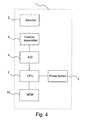
- FIG. 4 shows, in a reduced block chart, an electronic device 1 according to a preferred embodiment of the invention.
- This device 1 preferably comprises at least control means 7, such as a processor 7, a memory 10, sensor means 8, such as a position detector 8, at least one selector 2, an A/D converter 9, and a button 3 which can also be arranged in connection with the selector 2.
- the PIN code or selected symbol is accepted by pressing the button 3.
- the position detector 8 reads the position of the selector 2 which is converted by the A/D converter 9 into a digital format and stored in the memory 10.
- each selector is separately read, converted into digital format, and stored in the memory 10.
- these symbols can be combined to one item of digital information, after which the processing of the PIN code can be started.
- the position data of all the selectors are compiled into one item of digital information just before the processor.
- a separate button 3 will not be needed.
- the movement of the selector is monitored e.g. at small intervals by means of the position detector 8, wherein the position detector detects a stoppage of the selector or a change in the direction of rotation.
- the selected symbol is read into the memory 10 of the electronic device 1 according to the previous case.
- the position detector 8 controls the movement of the selector at intervals.
- the processor 7 can count the number of revolutions on the basis of the position data obtained from the position detector.
- the pairing i . e . the setting up of a secure data transmission link
- a wireless device 11 Fig. 5
- a smart card reader which is the above-described electronic device 1.
- the user activates a pairing application in the wireless device, wherein this application remains waiting for the entering of PIN codes into the wireless device and the smart card reader.
- the user enters the PIN code (e.g. "4385") in the smart card reader by means of at least one selector 2 therein.
- the user enters the same PIN code in the wireless device by means of a keypad 13 and a display 14 therein, after which the user starts the pairing process from the wireless device.
- the wireless device and the smart card reader set up authentication keys on the basis of the PIN codes in a way known as such. If these authentication keys match, the pairing process can be continued. After this pairing process, a secure data transmission link has been set up between the smart card reader and the wireless device.
Landscapes
- Engineering & Computer Science (AREA)
- Computer Security & Cryptography (AREA)
- Signal Processing (AREA)
- Computer Networks & Wireless Communication (AREA)
- Physics & Mathematics (AREA)
- General Physics & Mathematics (AREA)
- Input From Keyboards Or The Like (AREA)
- Telephone Set Structure (AREA)
- Telephone Function (AREA)
- Transceivers (AREA)
- Lock And Its Accessories (AREA)
Applications Claiming Priority (2)
| Application Number | Priority Date | Filing Date | Title |
|---|---|---|---|
| FI20000529 | 2000-03-08 | ||
| FI20000529A FI20000529L (fi) | 2000-03-08 | 2000-03-08 | Menetelmä avainkoodin syöttämiseksi elektroniikkalaitteeseen ja elektroniikkalaite |
Publications (2)
| Publication Number | Publication Date |
|---|---|
| EP1132933A2 true EP1132933A2 (de) | 2001-09-12 |
| EP1132933A3 EP1132933A3 (de) | 2004-03-24 |
Family
ID=8557871
Family Applications (1)
| Application Number | Title | Priority Date | Filing Date |
|---|---|---|---|
| EP01660037A Withdrawn EP1132933A3 (de) | 2000-03-08 | 2001-02-22 | Verfahren zur Dateneingabe in einen elektronischen Apparat |
Country Status (4)
| Country | Link |
|---|---|
| US (1) | US20010021980A1 (de) |
| EP (1) | EP1132933A3 (de) |
| JP (1) | JP2001298531A (de) |
| FI (1) | FI20000529L (de) |
Cited By (7)
| Publication number | Priority date | Publication date | Assignee | Title |
|---|---|---|---|---|
| WO2003005285A1 (en) * | 2001-07-02 | 2003-01-16 | Tds Todos Data System Ab | A card reader and a method for reading of cards |
| FR2862588A1 (fr) * | 2003-11-21 | 2005-05-27 | Olivier Chabert | Systeme antivol pour vehicule notamment contre le "car-jacking" |
| WO2007105032A3 (en) * | 2006-03-10 | 2008-05-02 | Sony Ericsson Mobile Comm Ab | Electronic equipment with data transfer function using motion and method |
| US7986917B2 (en) | 2006-07-10 | 2011-07-26 | Sony Ericsson Mobile Communications Ab | Method and system for data transfer from a hand held device |
| US8170186B2 (en) | 2008-04-07 | 2012-05-01 | Sony Mobile Communications Ab | Electronic device with motion controlled functions |
| EP1681412A4 (de) * | 2003-10-10 | 2012-06-27 | Shanghai Buddy Technology Co Ltd | Elektronische codeschloss-eingabevorrichtung, eingabeverfahren und anwendung davon |
| WO2021090200A1 (fr) * | 2019-11-04 | 2021-05-14 | Laurent Favre | Dispositif mécatronique agencé pour s'intégrer dans un appareil portatif comportant une pièce mécanique rotative servant à afficher et saisir un code pour exécuter une commande |
Families Citing this family (23)
| Publication number | Priority date | Publication date | Assignee | Title |
|---|---|---|---|---|
| JP3707407B2 (ja) * | 2001-08-28 | 2005-10-19 | セイコーエプソン株式会社 | パスワードを投写するプロジェクタ |
| JP2003143326A (ja) * | 2001-11-07 | 2003-05-16 | Canon Inc | 無線通信システム、情報機器、公衆回線端末、電子認証カード、ペアリングid設定方法、記憶媒体、及びプログラム |
| US7966497B2 (en) * | 2002-02-15 | 2011-06-21 | Qualcomm Incorporated | System and method for acoustic two factor authentication |
| US7401224B2 (en) * | 2002-05-15 | 2008-07-15 | Qualcomm Incorporated | System and method for managing sonic token verifiers |
| US7293071B2 (en) * | 2002-05-27 | 2007-11-06 | Seiko Epson Corporation | Image data transmission system, process and program, image data output device and image display device |
| AU2003266320A1 (en) * | 2002-09-16 | 2004-04-30 | Telefonaktiebolaget Lm Ericsson (Publ) | Secure access to a subscription module |
| JP4490637B2 (ja) * | 2003-01-27 | 2010-06-30 | シチズンホールディングス株式会社 | 個人認証端末 |
| JP2004287160A (ja) * | 2003-03-24 | 2004-10-14 | Seiko Epson Corp | 画像表示システム、プロジェクタ、画像表示方法、プロジェクタ制御方法、画像表示プログラムおよびプロジェクタ制御プログラム |
| JP2005208823A (ja) | 2004-01-21 | 2005-08-04 | Seiko Epson Corp | プロジェクタのネットワークシステム |
| JP4701615B2 (ja) * | 2004-01-23 | 2011-06-15 | ソニー株式会社 | 情報記憶装置 |
| EP1752937A1 (de) * | 2005-07-29 | 2007-02-14 | Research In Motion Limited | System und Verfahren zur verschlüsselten Eingabe einer persönlichen Identifizierungsnummer für eine Chipkarte |
| US7878395B2 (en) | 2005-09-08 | 2011-02-01 | Research In Motion Limited | Alerting a smart card reader of probable wireless communication |
| KR100762635B1 (ko) * | 2005-11-30 | 2007-10-01 | 삼성전자주식회사 | 휴대 단말기의 키 입력 장치 |
| JP5040341B2 (ja) * | 2006-04-04 | 2012-10-03 | セイコーエプソン株式会社 | プロジェクタシステム |
| US20090006846A1 (en) * | 2007-06-27 | 2009-01-01 | Apple Inc. | Bluetooth device as security access key |
| US20140304834A1 (en) * | 2011-10-04 | 2014-10-09 | Andrew Hulse | Personalized Secure Data Access Techniques |
| US20130110293A1 (en) * | 2011-10-31 | 2013-05-02 | Harald Illig | Remotely-controlled water sprinkling system and method |
| US9312949B1 (en) * | 2013-03-05 | 2016-04-12 | Square, Inc. | Pairing techniques for a wireless card reader |
| US9245104B2 (en) | 2014-01-10 | 2016-01-26 | Here Global B.V. | Method and apparatus for providing security with a multi-function physical dial of a communication device |
| US11481750B2 (en) | 2015-06-30 | 2022-10-25 | Block, Inc. | Pairing a payment object reader with a point-of-sale terminal |
| US11087315B2 (en) | 2015-09-24 | 2021-08-10 | Square, Inc. | Server-assisted pairing for wireless communications |
| US12207322B2 (en) | 2015-09-24 | 2025-01-21 | Block, Inc. | Server-assisted pairing for wireless communications |
| US11871237B1 (en) | 2016-06-30 | 2024-01-09 | Block, Inc. | Pairing a payment object reader with a point-of-sale terminal |
Family Cites Families (14)
| Publication number | Priority date | Publication date | Assignee | Title |
|---|---|---|---|---|
| DE867502C (de) * | 1949-02-23 | 1953-02-19 | Josef Schelle | Elektrisches Vexierschloss |
| US5168520A (en) * | 1984-11-30 | 1992-12-01 | Security Dynamics Technologies, Inc. | Method and apparatus for personal identification |
| US5021916A (en) * | 1989-03-02 | 1991-06-04 | Ultimate Security, Inc. | Theft deterring security system for attachment to powered appliances |
| US5550358A (en) * | 1991-01-31 | 1996-08-27 | Tait; Robert A. R. | Non-contacting transaction system |
| JPH0530010A (ja) * | 1991-07-22 | 1993-02-05 | Mitsubishi Electric Corp | 無線機 |
| JP3268467B2 (ja) * | 1992-09-08 | 2002-03-25 | 株式会社日立製作所 | 電話機 |
| US5435185A (en) * | 1993-08-16 | 1995-07-25 | Eagan; Chris S. | Electronic instrument for locating and diagnosing automotive chassis sounds |
| US5627355A (en) * | 1994-07-13 | 1997-05-06 | Rahman; Sam | Transaction device, equipment and method for protecting account numbers and their associated personal identification numbers |
| SE506506C2 (sv) * | 1995-04-11 | 1997-12-22 | Au System | Elektronisk transaktionsterminal, telekommunikationssystem innefattande en elektronisk transaktionsterminal, smart kort som elektronisk transaktionsterminal samt metod för överföring av elektroniska krediter |
| US6009465A (en) * | 1996-01-22 | 1999-12-28 | Svi Systems, Inc. | Entertainment and information systems and related management networks for a remote video delivery system |
| US7123936B1 (en) * | 1998-02-18 | 2006-10-17 | Ericsson Inc. | Cellular phone with expansion memory for audio and video storage |
| US6098878A (en) * | 1998-04-30 | 2000-08-08 | Ericsson Inc. | Tariff management apparatus and method for communications terminals using smart cards |
| US6377685B1 (en) * | 1999-04-23 | 2002-04-23 | Ravi C. Krishnan | Cluster key arrangement |
| US6549768B1 (en) * | 1999-08-24 | 2003-04-15 | Nokia Corp | Mobile communications matching system |
-
2000
- 2000-03-08 FI FI20000529A patent/FI20000529L/fi not_active Application Discontinuation
-
2001
- 2001-02-22 EP EP01660037A patent/EP1132933A3/de not_active Withdrawn
- 2001-03-07 US US09/801,985 patent/US20010021980A1/en not_active Abandoned
- 2001-03-08 JP JP2001065025A patent/JP2001298531A/ja active Pending
Cited By (10)
| Publication number | Priority date | Publication date | Assignee | Title |
|---|---|---|---|---|
| WO2003005285A1 (en) * | 2001-07-02 | 2003-01-16 | Tds Todos Data System Ab | A card reader and a method for reading of cards |
| US7104457B2 (en) | 2001-07-02 | 2006-09-12 | Tds Todos Data System Ab | Card reader and a method for reading of cards |
| EP1681412A4 (de) * | 2003-10-10 | 2012-06-27 | Shanghai Buddy Technology Co Ltd | Elektronische codeschloss-eingabevorrichtung, eingabeverfahren und anwendung davon |
| US8638227B2 (en) | 2003-10-10 | 2014-01-28 | Shanghai Buddy Technological Co., Ltd. | Input device, input method and application of electronic combination lock |
| FR2862588A1 (fr) * | 2003-11-21 | 2005-05-27 | Olivier Chabert | Systeme antivol pour vehicule notamment contre le "car-jacking" |
| WO2007105032A3 (en) * | 2006-03-10 | 2008-05-02 | Sony Ericsson Mobile Comm Ab | Electronic equipment with data transfer function using motion and method |
| US7986917B2 (en) | 2006-07-10 | 2011-07-26 | Sony Ericsson Mobile Communications Ab | Method and system for data transfer from a hand held device |
| US8170186B2 (en) | 2008-04-07 | 2012-05-01 | Sony Mobile Communications Ab | Electronic device with motion controlled functions |
| WO2021090200A1 (fr) * | 2019-11-04 | 2021-05-14 | Laurent Favre | Dispositif mécatronique agencé pour s'intégrer dans un appareil portatif comportant une pièce mécanique rotative servant à afficher et saisir un code pour exécuter une commande |
| CH716762A1 (fr) * | 2019-11-04 | 2021-05-14 | Favre Laurent | Dispositif mécatronique agencé pour s'intégrer dans un appareil portatif comportant une pièce mécanique rotative servant à afficher et saisir un code pour exécuter une commande. |
Also Published As
| Publication number | Publication date |
|---|---|
| FI20000529A0 (fi) | 2000-03-08 |
| FI20000529A7 (fi) | 2001-09-09 |
| FI20000529L (fi) | 2001-09-09 |
| EP1132933A3 (de) | 2004-03-24 |
| JP2001298531A (ja) | 2001-10-26 |
| US20010021980A1 (en) | 2001-09-13 |
Similar Documents
| Publication | Publication Date | Title |
|---|---|---|
| EP1132933A2 (de) | Verfahren zur Dateneingabe in einen elektronischen Apparat | |
| US6756969B2 (en) | Keypads for electrical devices | |
| US4914281A (en) | Identification apparatus for operating secure equipment | |
| US10554650B2 (en) | Directional sensing mechanism and communications authentication | |
| JP3981017B2 (ja) | 移動通信端末機器 | |
| JP3951193B2 (ja) | 通信端末装置 | |
| US7505799B2 (en) | Mobile electronic apparatus and function control method and program for the mobile electronic apparatus | |
| CN101292213B (zh) | 用于输入密码等的输入装置以及设有该输入装置的移动电话装置 | |
| EP0962852A2 (de) | Elektronisches Gerät und Steuerungsvorrichtung | |
| US7613446B2 (en) | Wireless mobile phone with authenticated mode of operation including finger print based authentication | |
| US5905964A (en) | Portable communication apparatus | |
| JP2001236859A (ja) | ロータリ・スイッチ | |
| US20020005837A1 (en) | Portable device with text entry | |
| JP5109927B2 (ja) | 端末装置及び表示制御方法 | |
| JP2007503662A (ja) | 構成の設定を改ざんされにくい無線通信デバイス | |
| US7705838B2 (en) | Movable user interface | |
| WO2002069281A2 (en) | Chip reader and identification method for verifying the user authorisation of a chip user | |
| KR101212034B1 (ko) | 이동통신 단말기에서 블루투스 기기 연결 장치 및 방법 | |
| JP2003283649A (ja) | 通信装置 | |
| JP2007300422A (ja) | 移動通信端末装置 | |
| JP4562681B2 (ja) | 無線通信装置及び無線通信システム | |
| JP4859427B2 (ja) | 認証システム及び認証システム用無線タグ装置 | |
| JP2002091680A (ja) | スイッチ装置および携帯端末 | |
| KR100913086B1 (ko) | 이동통신 단말기 및 이것의 문자인식 방법 | |
| JP4232116B2 (ja) | 装置及び制御方法 |
Legal Events
| Date | Code | Title | Description |
|---|---|---|---|
| PUAI | Public reference made under article 153(3) epc to a published international application that has entered the european phase |
Free format text: ORIGINAL CODE: 0009012 |
|
| AK | Designated contracting states |
Kind code of ref document: A2 Designated state(s): AT BE CH CY DE DK ES FI FR GB GR IE IT LI LU MC NL PT SE TR |
|
| AX | Request for extension of the european patent |
Free format text: AL;LT;LV;MK;RO;SI |
|
| RAP1 | Party data changed (applicant data changed or rights of an application transferred) |
Owner name: NOKIA CORPORATION |
|
| PUAL | Search report despatched |
Free format text: ORIGINAL CODE: 0009013 |
|
| AK | Designated contracting states |
Kind code of ref document: A3 Designated state(s): AT BE CH CY DE DK ES FI FR GB GR IE IT LI LU MC NL PT SE TR |
|
| AX | Request for extension of the european patent |
Extension state: AL LT LV MK RO SI |
|
| 17P | Request for examination filed |
Effective date: 20040922 |
|
| 17Q | First examination report despatched |
Effective date: 20041021 |
|
| AKX | Designation fees paid |
Designated state(s): DE FR GB NL |
|
| STAA | Information on the status of an ep patent application or granted ep patent |
Free format text: STATUS: THE APPLICATION IS DEEMED TO BE WITHDRAWN |
|
| 18D | Application deemed to be withdrawn |
Effective date: 20050301 |