EP1132984A2 - Nichtwässrige-Elektrolyt Sekundärbatterie - Google Patents
Nichtwässrige-Elektrolyt Sekundärbatterie Download PDFInfo
- Publication number
- EP1132984A2 EP1132984A2 EP01105297A EP01105297A EP1132984A2 EP 1132984 A2 EP1132984 A2 EP 1132984A2 EP 01105297 A EP01105297 A EP 01105297A EP 01105297 A EP01105297 A EP 01105297A EP 1132984 A2 EP1132984 A2 EP 1132984A2
- Authority
- EP
- European Patent Office
- Prior art keywords
- alloy
- aqueous electrolyte
- negative electrode
- secondary battery
- electrolyte secondary
- Prior art date
- Legal status (The legal status is an assumption and is not a legal conclusion. Google has not performed a legal analysis and makes no representation as to the accuracy of the status listed.)
- Granted
Links
Images


Classifications
-
- H—ELECTRICITY
- H01—ELECTRIC ELEMENTS
- H01M—PROCESSES OR MEANS, e.g. BATTERIES, FOR THE DIRECT CONVERSION OF CHEMICAL ENERGY INTO ELECTRICAL ENERGY
- H01M4/00—Electrodes
- H01M4/02—Electrodes composed of, or comprising, active material
- H01M4/13—Electrodes for accumulators with non-aqueous electrolyte, e.g. for lithium-accumulators; Processes of manufacture thereof
- H01M4/136—Electrodes based on inorganic compounds other than oxides or hydroxides, e.g. sulfides, selenides, tellurides, halogenides or LiCoFy
-
- H—ELECTRICITY
- H01—ELECTRIC ELEMENTS
- H01M—PROCESSES OR MEANS, e.g. BATTERIES, FOR THE DIRECT CONVERSION OF CHEMICAL ENERGY INTO ELECTRICAL ENERGY
- H01M10/00—Secondary cells; Manufacture thereof
- H01M10/05—Accumulators with non-aqueous electrolyte
- H01M10/052—Li-accumulators
-
- H—ELECTRICITY
- H01—ELECTRIC ELEMENTS
- H01M—PROCESSES OR MEANS, e.g. BATTERIES, FOR THE DIRECT CONVERSION OF CHEMICAL ENERGY INTO ELECTRICAL ENERGY
- H01M4/00—Electrodes
- H01M4/02—Electrodes composed of, or comprising, active material
- H01M4/36—Selection of substances as active materials, active masses, active liquids
- H01M4/38—Selection of substances as active materials, active masses, active liquids of elements or alloys
-
- H—ELECTRICITY
- H01—ELECTRIC ELEMENTS
- H01M—PROCESSES OR MEANS, e.g. BATTERIES, FOR THE DIRECT CONVERSION OF CHEMICAL ENERGY INTO ELECTRICAL ENERGY
- H01M4/00—Electrodes
- H01M4/02—Electrodes composed of, or comprising, active material
- H01M4/36—Selection of substances as active materials, active masses, active liquids
- H01M4/38—Selection of substances as active materials, active masses, active liquids of elements or alloys
- H01M4/386—Silicon or alloys based on silicon
-
- H—ELECTRICITY
- H01—ELECTRIC ELEMENTS
- H01M—PROCESSES OR MEANS, e.g. BATTERIES, FOR THE DIRECT CONVERSION OF CHEMICAL ENERGY INTO ELECTRICAL ENERGY
- H01M4/00—Electrodes
- H01M4/02—Electrodes composed of, or comprising, active material
- H01M4/36—Selection of substances as active materials, active masses, active liquids
- H01M4/38—Selection of substances as active materials, active masses, active liquids of elements or alloys
- H01M4/387—Tin or alloys based on tin
-
- H—ELECTRICITY
- H01—ELECTRIC ELEMENTS
- H01M—PROCESSES OR MEANS, e.g. BATTERIES, FOR THE DIRECT CONVERSION OF CHEMICAL ENERGY INTO ELECTRICAL ENERGY
- H01M4/00—Electrodes
- H01M4/02—Electrodes composed of, or comprising, active material
- H01M2004/026—Electrodes composed of, or comprising, active material characterised by the polarity
- H01M2004/027—Negative electrodes
-
- Y—GENERAL TAGGING OF NEW TECHNOLOGICAL DEVELOPMENTS; GENERAL TAGGING OF CROSS-SECTIONAL TECHNOLOGIES SPANNING OVER SEVERAL SECTIONS OF THE IPC; TECHNICAL SUBJECTS COVERED BY FORMER USPC CROSS-REFERENCE ART COLLECTIONS [XRACs] AND DIGESTS
- Y02—TECHNOLOGIES OR APPLICATIONS FOR MITIGATION OR ADAPTATION AGAINST CLIMATE CHANGE
- Y02E—REDUCTION OF GREENHOUSE GAS [GHG] EMISSIONS, RELATED TO ENERGY GENERATION, TRANSMISSION OR DISTRIBUTION
- Y02E60/00—Enabling technologies; Technologies with a potential or indirect contribution to GHG emissions mitigation
- Y02E60/10—Energy storage using batteries
Definitions
- the present invention relates to improvements of a negative electrode of non-aqueous electrolyte secondary batteries. More specifically, this invention relates to a non-aqueous electrolyte secondary battery having a high electric capacity, having a highly reliable negative electrode free from dendrites, and offering a high energy density without a fear of occurrence of internal short circuit caused by dendrites.
- Non-aqueous electrolyte secondary batteries having a negative electrode of lithium or lithium compounds have been attracting a great deal of attention because they afford a high discharge voltage and a high energy density, and therefore extensive investigations have been made about such batteries.
- Conventionally known positive electrode active materials for use in the non-aqueous electrolyte secondary battery include oxides or chalcogenides of transition metals such as LiMn 2 O 4 , LiCoO 2 , LiNiO 2 , V 2 O 5 , Cr 2 O 5 , MnO 2 , TiS 2 , MoS 2 and the like. These compounds have a layered or tunneled crystal structure permitting intercalation and deintercalation of lithium ions. On the other hand, as a negative electrode active material, the use of metallic lithium has been investigated extensively.
- metallic lithium when used in the negative electrode, has an inevitable issue of deposition of lithium dendrites on the surface of metallic lithium during the charge, which impairs charge and discharge efficiency or induces internal short circuit due to the contact of such lithium dendrites with the positive electrode.
- lithium ion batteries using, in the negative electrode, a graphite type carbon material which is capable of reversibly absorbing therein and desorbing therefrom lithium and which is excellent in terms of cycle characteristics and safety although it has smaller capacity than metallic lithium.
- the present invention has an object to provide a negative electrode which permits a non-aqueous electrolyte secondary battery having a high capacity and excellent charge and discharge cycle characteristics.
- the present invention provides a negative electrode comprising an alloy material which absorbs lithium during charge and desorbs lithium during discharge, developing no dendrites, offering a high electric capacity, suffering little expansion during the charge, and having a long cycle life.
- the present invention provides a non-aqueous electrolyte secondary battery comprising a rechargeable positive electrode, a non-aqueous electrolyte containing a lithium salt and a rechargeable negative electrode, wherein the negative electrode includes an alloy having a hexagonal closest packing structure and a Ni 2 In type structure composed of at least two elements.
- the aforementioned alloy preferably comprises an intermetallic compound containing at least one element selected from the group consisting of Sn, Si and In.
- the aforementioned alloy preferably comprises at least one intermetallic compound selected from the group consisting of Ti 2 Sn, NiCoSn, Mn 2 Sn, Ni 3 Sn 2 , BeSiZr, Co 3 Sn 2 , Cu 2 In, Ni 2 In, Ni 2 Si, Pd 3 Sn 2 and Rh 3 Sn 2 .
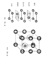
- FIG. 1A is a diagram illustrating a model of a crystal structure of a negative electrode alloy of the present invention.
- FIG. 1B is a diagram showing a laminated structure in the z axis direction of the above crystal structure.
- FIG. 2 is a longitudinal cross sectional view of a test cell used in examples of the present invention.
- FIG. 3 is a longitudinal cross sectional view of a cylindrical battery used in examples of the present invention.
- the negative electrode of the present invention comprises an alloy having a hexagonal closest packing structure and a Ni 2 In type structure composed of at least two elements.
- the alloy negative electrode of this type charges and discharges by electrochemical alloying and deintercalation reaction between an element such as tin, aluminum and the like, and lithium.
- the alloy negative electrode repeats expansion and contraction along with the intercalation and deintercalation of lithium, and the negative electrode is liable to be pulverized by mechanical stress. This phenomenon is a principal cause for the deterioration of the cycle characteristics.
- the negative electrode using the alloy of the present invention does not expand or contract excessively although it offers a high capacity, and it exhibits favorable charge and discharge cycle characteristics.
- the reason for this is considered that, while the aforementioned conventional alloy negative electrode causes the reaction as shown in the following formula (1) or (2), the alloy of the present invention causes the reaction of the following formula (3).
- M represents an element capable of being electrochemically alloyed with lithium, such as tin, aluminum and the like.
- M 2 is an element inactive with lithium, such as iron, nickel, copper and the like.
- X, y and z are respectively any positive numbers.
- a part of M 1 and M 2 may be replaced with other elements provided that they form effectively the aforementioned Ni 2 In type structure.
- FIG. 1A and FIG. 1B show a model of the structure of the alloy of the invention.
- FIG. 1A shows a model of the crystal structure
- FIG. 1B shows a laminated structure in the z axis direction.
- M 1 and M 2 the element corresponding to M 1 takes positions of (1/3, 2/3, 1/4) and (2/3, 1/3, 3/4) in FIG. 1A.
- the layers formed only with M 2 and the layers in which M 1 and M 2 align alternately are stacked in the z axis direction in a layered structure.
- This structure is considered to stabilize the initial structure by preventing excessive lithium from being intercalated in the layers formed only with M 2 during alloying reaction (charge) between M 1 and lithium.
- M 1 and M 2 are present alternately on a plane constituting the same layer, coagulation of M 1 atoms caused by the alloying reaction with lithium is suppressed, facilitating further stabilization of the structure.
- the element selected as M may be any element provided that it alloys electrochemically with lithium. Sn, Si and In are preferable, and Sn and In are particularly preferable.
- the intermetallic compound constituting the alloy of the present invention is preferably at least one compound selected from the group consisting of Ti 2 Sn, NiCoSn, Mn 2 Sn, Ni 3 Sn 2 , BeSiZr, Co 3 Sn 2 , Cu 2 In, Ni 2 In, Ni 2 Si, Pd 3 Sn 2 and Rh 3 Sn 2 . Particularly preferably, it is selected from the group consisting of Ti 2 Sn, NiCoSn, Mn 2 Sn, Co 3 Sn 2 , Cu 2 In and Ni 2 In.
- the alloy of the present invention is preferably either amorphous or low crystalline. Further, it is desirable that the grain size is 10 ⁇ m or less. Particularly preferably, the grain size is 1 ⁇ m or less.
- the charge and discharge capacity tends to increase by the fact that the alloy is amorphous or low crystalline. The reason for this is considered that a space capable of accommodating lithium is created by being amorphous. It is considered that, by being low crystalline or minute crystalline, the grain size is decreased, making lithium ions readily pass through the space between the grains, thereby facilitating the reaction.
- the average particle size of the alloy used in the negative electrode of the present invention is preferably 45 ⁇ m or less, particularly preferably 30 ⁇ m or less.
- the reason for this is, since the thickness of the mixture layer of the negative electrode plate is generally 100 ⁇ m or less, the surface of the electrode plate becomes uneven if the particle size of the alloy is larger, which may cause short circuit or the like.
- the negative electrode of the present invention preferably comprises a mixture of the alloy satisfying the condition as above with a conductive agent.
- a conductive agent it is preferred to use a graphite or carbon material such as carbon black, acetylene black and the like.
- the characteristics of the negative electrode are particularly improved when a graphite material is added as the conductive agent. This is considered not only because graphite itself is involved in the charge and discharge reaction, but also because it has an electrolyte-retaining property of carbon material and an ability to ease the contraction and the expansion of the alloy.
- the alloy of the present invention is preferably synthesized by a solid phase synthesizing method such as mechanical alloying method, mechanomilling method and the like.
- the solid phase synthesizing method whose typical example is mechanical alloying method, is suitable for obtaining amorphous or low crystalline alloys of a fine particle diameter. This is the most suitable synthesizing method for the alloy of the present invention.
- melt quenching method whose typical example is roll quenching method.
- melt quenching method there are also water atomizing method, gas atomizing method, melt spinning method and the like.
- atomizing method is suitable for producing a large quantity of low crystalline alloys having a fine particle diameter.
- the alloys used in the examples were prepared in the following synthesizing methods.
- Powders of single elements (all of which have an average particle diameter of 75 ⁇ m or less) were mixed at a predetermined molar ratio and were put in a stainless steel bowl mill together with stainless steel bowls of 25 mm in diameter.
- the bowl mill was rotated for 24 hours with a roller with a rotation speed of 120 rpm under an argon atmosphere, and thereby an alloy was synthesized.
- the alloy obtained by the mechanical alloying method was recovered, it was passed through a sieve of 45 microns mesh, thereby giving active materials having average particle diameters of at largest 24 ⁇ m.
- the active materials obtained were all amorphous or low crystalline and their grain sizes were, at largest, 0.7 ⁇ m of Ni 2 Si.
- an ingot obtained was pulverized into a coarse powder to give a raw material for atomization.
- argon was sprayed at a spraying pressure of 100 kgf/cm 2 at the molten raw material spouting from a nozzle of a melting pot made of alumina, and thereby alloy particles were obtained.
- a high frequency melting furnace was used for melting the atomization material.
- the alloy obtained by the gas atomizing method was recovered, it was passed through a sieve of 45 microns mesh, giving active materials having an average particle diameter of at largest 30 ⁇ m.
- the active materials obtained were all low crystalline, and their grain sizes were, at largest, 5.4 ⁇ m of BeSiZr.
- a single roll quenching apparatus was used as a roll quenching apparatus.
- a material for the roll copper was used; as a material for the nozzle, quartz was generally used, and in the case of a material having a high melting point such as Ti, a graphite nozzle was used.
- the roll rotating speed was set to a circumferential speed of 10 m/s, and the gas spraying pressure was set to 10 kgf/cm 2 .
- the alloy obtained by the roll quenching method was recovered, it was pulverized into a coarse powder with a cutter mill. Then it was passed through a sieve of 45 microns mesh to give active materials having average particle diameters of at largest 33 ⁇ m.
- the active materials obtained were all either amorphous or low crystalline, and their grain sizes were, at largest, 1.8 ⁇ m of BeSiZr.
- FIG. 2 shows a test cell configured using this electrode.
- the electrode 1 is placed in the center of a cell case 2, and a separator 3 made of microporous polypropylene film is mounted on the electrode 1.
- cathode polarization (corresponding to charge when the electrode 1 is regarded as the negative electrode) was carried out at a constant current of 2 mA until the electrode 1 showed 0 V relative to the lithium counter electrode 4.
- anode polarization (corresponding to discharge) was carried out until the electrode 1 showed 1.5 V relative to the lithium counter electrode 4. Subsequently, a cycle of a cathode polarization and an anode polarization was repeated.
- cylindrical batteries as shown in FIG. 3 were prepared.
- the preparation procedure of the batteries was as follows.
- LiMn 1.8 Co 0.2 O 4 as the positive electrode active material was synthesized by mixing Li 2 CO 3 , Mn 3 O 4 and CoCO 3 at a predetermined molar ratio and heating the mixture at 900 C. The resulting material was classified to 100 mesh or less to give the positive electrode active material.
- 10 g of a carbon powder as a conductive agent and 8 g (in terms of the resin content) of an aqueous dispersion of polytetrafluoroethylene as a binder and a pure water were added, and a paste was prepared therefrom. The paste was applied onto a core material of aluminum, dried, and rolled to give a positive electrode plate.
- each active material, a graphite powder as a conductive agent and a polytetrafluoroethylene powder as a binder were mixed at a weight ratio of 80 : 20 : 10.
- An petroleum type solvent was added to this mixture and they were prepared into a paste. After the paste was applied onto a core material of copper, it was dried at 100 ° C to give a negative electrode plate. Porous polypropylene film was used as a separator.
- a positive electrode lead 14 of aluminum was fixed by spot welding, and to the negative electrode plate 12, a negative electrode lead 15 of copper was fixed by spot welding.
- the positive electrode plate 11, the negative electrode plate 12, and the separator 13 separating the two electrode plates were spirally wound to form an electrode assembly.
- This electrode assembly was inserted into a battery case 18, with insulating plates 16 and 17 made of polypropylene placed on top and bottom of the electrode assembly, and a step was formed in an upper part of the battery case 18. Subsequently, the same non-aqueous electrolyte as described previously was poured into the case, and then the opening of the case 18 was sealed with a sealing plate 19 having a positive electrode terminal 20.
- the positive electrode lead 14 was connected to the positive electrode terminal 20 on the sealing plate 19 and the negative electrode lead 15 was connected to the case 18.
- Example Active material Synthesizing method Discharge capacity Capacity maintenance rate mAh/g mAh/cc % 1 Ti 2 Sn MA 330 780 95 2 RQ 300 750 94 3 NiCoSn MA 370 980 97 4 AT 330 1010 90 5 RQ 340 990 94 6 Mn 2 Sn MA 380 950 96 7 AT 340 910 91 8 RQ 370 940 92 9 Ni 3 Sn 2 MA 440 1020 97 1 0 AT 400 1000 88 1 1 RQ 410 1000 91 1 2 Co 3 Sn 2 MA 480 1070 94 1 3 AT 450 1030 89 1 4 RQ 460 1050 89 1 5 Pd 3 Sn 2 MA 460 1150 95 1 6 RQ 420 1080 93 1 7 Rh 3 Sn 2 MA 450 1180 94 1 8 RQ 390 1100 90 1 9 Cu 2 In MA 390 1070 93 2 0 AT 340 970 88 2 1 RQ 370 1030 90 2 2 Ni 2 In MA 400 1200
- MA, AT and RQ represent respectively mechanical alloying method, gas atomizing method and roll quenching method.
- an alloy having a known composition was prepared by the same synthesizing method as described above, and the same test as above was carried out. Also, the same test was carried out with a graphite negative electrode (thermally treated mesophase small sphere), which is generally in use.
- the electrode mixture containing graphite was prepared by mixing a graphite powder and polytetrafluoroethylene at a weight ratio of 10 : 1. The test results are shown in Table 2.
- the alloy negative electrodes of the comparative examples generally have a high capacity but have a short cycle life.
- the graphite negative electrode has a long cycle life but a low capacity.
- the battery using the active materials of the present invention in the negative electrode has a high capacity compared with those of the comparative examples, and further, they have remarkably improved cycle characteristics.
- the present invention provides a negative electrode having a high capacity and extremely excellent cycle life characteristics. Accordingly, the present invention provides a non-aqueous electrolyte secondary battery which has a higher energy density and which is highly reliable without a fear of occurrence of short circuit caused by dendrites.
- the present invention provides a rechargeable negative electrode for a non-aqueous electrolyte secondary battery comprising an alloy material which absorbs lithium during charge and desorbs lithium during discharge, and having a long cycle life.
- the negative electrode includes an alloy having a hexagonal closest packing structure and a Ni 2 In type structure composed of at least two elements.
Landscapes
- Chemical & Material Sciences (AREA)
- Chemical Kinetics & Catalysis (AREA)
- Electrochemistry (AREA)
- General Chemical & Material Sciences (AREA)
- Engineering & Computer Science (AREA)
- Manufacturing & Machinery (AREA)
- Inorganic Chemistry (AREA)
- Materials Engineering (AREA)
- Secondary Cells (AREA)
- Battery Electrode And Active Subsutance (AREA)
Applications Claiming Priority (2)
| Application Number | Priority Date | Filing Date | Title |
|---|---|---|---|
| JP2000061123A JP4439660B2 (ja) | 2000-03-06 | 2000-03-06 | 非水電解質二次電池 |
| JP2000061123 | 2000-03-06 |
Publications (3)
| Publication Number | Publication Date |
|---|---|
| EP1132984A2 true EP1132984A2 (de) | 2001-09-12 |
| EP1132984A3 EP1132984A3 (de) | 2001-09-19 |
| EP1132984B1 EP1132984B1 (de) | 2006-07-12 |
Family
ID=18581322
Family Applications (1)
| Application Number | Title | Priority Date | Filing Date |
|---|---|---|---|
| EP01105297A Expired - Lifetime EP1132984B1 (de) | 2000-03-06 | 2001-03-05 | Nichtwässrige-Elektrolyt Sekundärbatterie |
Country Status (4)
| Country | Link |
|---|---|
| US (1) | US6593030B2 (de) |
| EP (1) | EP1132984B1 (de) |
| JP (1) | JP4439660B2 (de) |
| DE (1) | DE60121381T2 (de) |
Families Citing this family (9)
| Publication number | Priority date | Publication date | Assignee | Title |
|---|---|---|---|---|
| US20030211390A1 (en) * | 2000-12-22 | 2003-11-13 | Dahn Jeffrey R. | Grain boundary materials as electrodes for lithium ion cells |
| AU2003302519A1 (en) | 2002-11-29 | 2004-06-23 | Mitsui Mining And Smelting Co., Ltd. | Negative electrode for non-aqueous electrolyte secondary cell and method for manufacture thereof, and non-aqueous electrolyte secondary cell |
| US7169328B2 (en) * | 2003-01-17 | 2007-01-30 | T/J Technologies, Inc. | Multiphase nanocomposite material and method for its manufacture |
| JP3769277B2 (ja) * | 2003-04-17 | 2006-04-19 | 株式会社東芝 | 非水電解質二次電池 |
| JP4625672B2 (ja) * | 2003-10-30 | 2011-02-02 | 株式会社東芝 | 非水電解質二次電池 |
| FR2864348B1 (fr) * | 2003-12-18 | 2006-03-10 | Commissariat Energie Atomique | Accumulateur au lithium presentant a la fois un potentiel electrique et une capacite d'insertion du lthium eleves. |
| JP4127692B2 (ja) | 2004-03-23 | 2008-07-30 | 株式会社東芝 | 非水電解質二次電池 |
| JP5348448B2 (ja) * | 2007-10-29 | 2013-11-20 | 株式会社デンソー | 非水電解質電池 |
| CN103003984A (zh) | 2010-04-23 | 2013-03-27 | 新日铁住金株式会社 | 非水电解质二次电池的负极材料及其制造方法 |
Family Cites Families (9)
| Publication number | Priority date | Publication date | Assignee | Title |
|---|---|---|---|---|
| CA1086988A (en) * | 1978-02-14 | 1980-10-07 | Maheswar Sahoo | Magnesium-lithium alloy |
| US4950566A (en) | 1988-10-24 | 1990-08-21 | Huggins Robert A | Metal silicide electrode in lithium cells |
| JPH04126371A (ja) | 1990-09-18 | 1992-04-27 | Sanyo Electric Co Ltd | 非水電解質二次電池 |
| CN1074249A (zh) * | 1991-10-29 | 1993-07-14 | 维克托·I·特雷菲洛夫 | 能荷载高量客体的层状晶体材料 |
| JP3498380B2 (ja) | 1994-02-28 | 2004-02-16 | 宇部興産株式会社 | 非水二次電池 |
| JP3359164B2 (ja) | 1994-10-19 | 2002-12-24 | キヤノン株式会社 | 二次電池 |
| US5792574A (en) * | 1996-03-04 | 1998-08-11 | Sharp Kabushiki Kaisha | Nonaqueous secondary battery |
| JP3805053B2 (ja) | 1997-02-10 | 2006-08-02 | 旭化成エレクトロニクス株式会社 | リチウム二次電池 |
| US6855460B2 (en) * | 2001-02-08 | 2005-02-15 | The University Of Chicago | Negative electrodes for lithium cells and batteries |
-
2000
- 2000-03-06 JP JP2000061123A patent/JP4439660B2/ja not_active Expired - Fee Related
-
2001
- 2001-03-01 US US09/798,846 patent/US6593030B2/en not_active Expired - Lifetime
- 2001-03-05 DE DE60121381T patent/DE60121381T2/de not_active Expired - Lifetime
- 2001-03-05 EP EP01105297A patent/EP1132984B1/de not_active Expired - Lifetime
Also Published As
| Publication number | Publication date |
|---|---|
| US20010044046A1 (en) | 2001-11-22 |
| DE60121381D1 (de) | 2006-08-24 |
| EP1132984A3 (de) | 2001-09-19 |
| JP4439660B2 (ja) | 2010-03-24 |
| DE60121381T2 (de) | 2007-07-05 |
| EP1132984B1 (de) | 2006-07-12 |
| JP2001250541A (ja) | 2001-09-14 |
| US6593030B2 (en) | 2003-07-15 |
Similar Documents
| Publication | Publication Date | Title |
|---|---|---|
| EP0696075B1 (de) | Sekundärbatterie mit nichtwässrigem Elektrolyten | |
| US6265111B1 (en) | Non-aqueous electrolyte secondary battery | |
| JP5143852B2 (ja) | 非水電解質二次電池 | |
| KR100848792B1 (ko) | 비수전해액 2차 전지 | |
| US7682744B2 (en) | Lithium secondary battery | |
| JP2001015102A (ja) | 非水電解質二次電池およびその製造法 | |
| JP4056183B2 (ja) | 非水電解質二次電池用負極活物質および非水電解質二次電池 | |
| US6541157B1 (en) | Nonaqueous electrolyte battery having large capacity and long cycle life | |
| JPH1186853A (ja) | リチウム二次電池 | |
| US6761998B2 (en) | Non-aqueous electrolyte secondary cell | |
| US6593030B2 (en) | Non-aqueous electrolyte secondary battery | |
| JP3296204B2 (ja) | リチウム二次電池 | |
| US5939224A (en) | Nonaqueous electrolyte secondary battery | |
| JP3848187B2 (ja) | 非水電解質二次電池用負極材料及び非水電解質二次電池 | |
| CN100433420C (zh) | 电极材料、该电极材料的生产方法、电极以及非水电解质电池 | |
| JP2003157896A (ja) | 非水電解質二次電池 | |
| JP2001345098A (ja) | 非水電解質電池 | |
| JP2002151065A (ja) | 負極活物質及び非水電解質電池 | |
| JP2003282053A (ja) | 非水電解質電池用負極材料、負極及び非水電解質電池 | |
| JP2003151543A (ja) | 負極活物質及び非水電解質二次電池 | |
| JP2004193005A (ja) | 非水電解質電池用電極材料、電極及び非水電解質電池 | |
| JP2003022802A (ja) | 非水電解質電池用負極材料、負極及び非水電解質電池 | |
| JP2004185881A (ja) | 非水電解質電池用電極材料、電極及び非水電解質電池 | |
| JP2000133261A (ja) | 非水電解質二次電池とその製造法 | |
| JP2000173588A (ja) | 非水電解質二次電池 |
Legal Events
| Date | Code | Title | Description |
|---|---|---|---|
| PUAI | Public reference made under article 153(3) epc to a published international application that has entered the european phase |
Free format text: ORIGINAL CODE: 0009012 |
|
| PUAL | Search report despatched |
Free format text: ORIGINAL CODE: 0009013 |
|
| AK | Designated contracting states |
Kind code of ref document: A2 Designated state(s): AT BE CH CY DE DK ES FI FR GB GR IE IT LI LU MC NL PT SE TR Kind code of ref document: A2 Designated state(s): DE FR GB |
|
| AX | Request for extension of the european patent |
Free format text: AL;LT;LV;MK;RO;SI |
|
| AK | Designated contracting states |
Kind code of ref document: A3 Designated state(s): AT BE CH CY DE DK ES FI FR GB GR IE IT LI LU MC NL PT SE TR |
|
| AX | Request for extension of the european patent |
Free format text: AL;LT;LV;MK;RO;SI |
|
| 17P | Request for examination filed |
Effective date: 20011018 |
|
| AKX | Designation fees paid |
Free format text: DE FR GB |
|
| 17Q | First examination report despatched |
Effective date: 20050623 |
|
| GRAP | Despatch of communication of intention to grant a patent |
Free format text: ORIGINAL CODE: EPIDOSNIGR1 |
|
| GRAS | Grant fee paid |
Free format text: ORIGINAL CODE: EPIDOSNIGR3 |
|
| GRAA | (expected) grant |
Free format text: ORIGINAL CODE: 0009210 |
|
| AK | Designated contracting states |
Kind code of ref document: B1 Designated state(s): DE FR GB |
|
| REG | Reference to a national code |
Ref country code: GB Ref legal event code: FG4D |
|
| REF | Corresponds to: |
Ref document number: 60121381 Country of ref document: DE Date of ref document: 20060824 Kind code of ref document: P |
|
| ET | Fr: translation filed | ||
| PLBE | No opposition filed within time limit |
Free format text: ORIGINAL CODE: 0009261 |
|
| STAA | Information on the status of an ep patent application or granted ep patent |
Free format text: STATUS: NO OPPOSITION FILED WITHIN TIME LIMIT |
|
| 26N | No opposition filed |
Effective date: 20070413 |
|
| PGFP | Annual fee paid to national office [announced via postgrant information from national office to epo] |
Ref country code: GB Payment date: 20130228 Year of fee payment: 13 Ref country code: FR Payment date: 20130325 Year of fee payment: 13 |
|
| GBPC | Gb: european patent ceased through non-payment of renewal fee |
Effective date: 20140305 |
|
| REG | Reference to a national code |
Ref country code: FR Ref legal event code: ST Effective date: 20141128 |
|
| PG25 | Lapsed in a contracting state [announced via postgrant information from national office to epo] |
Ref country code: GB Free format text: LAPSE BECAUSE OF NON-PAYMENT OF DUE FEES Effective date: 20140305 Ref country code: FR Free format text: LAPSE BECAUSE OF NON-PAYMENT OF DUE FEES Effective date: 20140331 |
|
| PGFP | Annual fee paid to national office [announced via postgrant information from national office to epo] |
Ref country code: DE Payment date: 20200218 Year of fee payment: 20 |
|
| REG | Reference to a national code |
Ref country code: DE Ref legal event code: R071 Ref document number: 60121381 Country of ref document: DE |