EP1133012B1 - Steckbarer Klemmenkasten - Google Patents
Steckbarer Klemmenkasten Download PDFInfo
- Publication number
- EP1133012B1 EP1133012B1 EP01102297A EP01102297A EP1133012B1 EP 1133012 B1 EP1133012 B1 EP 1133012B1 EP 01102297 A EP01102297 A EP 01102297A EP 01102297 A EP01102297 A EP 01102297A EP 1133012 B1 EP1133012 B1 EP 1133012B1
- Authority
- EP
- European Patent Office
- Prior art keywords
- terminal box
- plug
- cast
- base part
- contact parts
- Prior art date
- Legal status (The legal status is an assumption and is not a legal conclusion. Google has not performed a legal analysis and makes no representation as to the accuracy of the status listed.)
- Expired - Lifetime
Links
Images


Classifications
-
- H—ELECTRICITY
- H02—GENERATION; CONVERSION OR DISTRIBUTION OF ELECTRIC POWER
- H02K—DYNAMO-ELECTRIC MACHINES
- H02K5/00—Casings; Enclosures; Supports
- H02K5/04—Casings or enclosures characterised by the shape, form or construction thereof
- H02K5/22—Auxiliary parts of casings not covered by groups H02K5/06-H02K5/20, e.g. shaped to form connection boxes or terminal boxes
- H02K5/225—Terminal boxes or connection arrangements
-
- H—ELECTRICITY
- H01—ELECTRIC ELEMENTS
- H01R—ELECTRICALLY-CONDUCTIVE CONNECTIONS; STRUCTURAL ASSOCIATIONS OF A PLURALITY OF MUTUALLY-INSULATED ELECTRICAL CONNECTING ELEMENTS; COUPLING DEVICES; CURRENT COLLECTORS
- H01R13/00—Details of coupling devices of the kinds covered by groups H01R12/70 or H01R24/00 - H01R33/00
- H01R13/46—Bases; Cases
- H01R13/502—Bases; Cases composed of different pieces
- H01R13/504—Bases; Cases composed of different pieces different pieces being moulded, cemented, welded, e.g. ultrasonic welding, or swaged together
-
- H—ELECTRICITY
- H01—ELECTRIC ELEMENTS
- H01R—ELECTRICALLY-CONDUCTIVE CONNECTIONS; STRUCTURAL ASSOCIATIONS OF A PLURALITY OF MUTUALLY-INSULATED ELECTRICAL CONNECTING ELEMENTS; COUPLING DEVICES; CURRENT COLLECTORS
- H01R43/00—Apparatus or processes specially adapted for manufacturing, assembling, maintaining, or repairing of line connectors or current collectors or for joining electric conductors
- H01R43/20—Apparatus or processes specially adapted for manufacturing, assembling, maintaining, or repairing of line connectors or current collectors or for joining electric conductors for assembling or disassembling contact members with insulating base, case or sleeve
- H01R43/24—Assembling by moulding on contact members
-
- H—ELECTRICITY
- H02—GENERATION; CONVERSION OR DISTRIBUTION OF ELECTRIC POWER
- H02K—DYNAMO-ELECTRIC MACHINES
- H02K11/00—Structural association of dynamo-electric machines with electric components or with devices for shielding, monitoring or protection
- H02K11/30—Structural association with control circuits or drive circuits
- H02K11/33—Drive circuits, e.g. power electronics
-
- H—ELECTRICITY
- H01—ELECTRIC ELEMENTS
- H01R—ELECTRICALLY-CONDUCTIVE CONNECTIONS; STRUCTURAL ASSOCIATIONS OF A PLURALITY OF MUTUALLY-INSULATED ELECTRICAL CONNECTING ELEMENTS; COUPLING DEVICES; CURRENT COLLECTORS
- H01R13/00—Details of coupling devices of the kinds covered by groups H01R12/70 or H01R24/00 - H01R33/00
- H01R13/40—Securing contact members in or to a base or case; Insulating of contact members
- H01R13/405—Securing in non-demountable manner, e.g. moulding, riveting
-
- H—ELECTRICITY
- H02—GENERATION; CONVERSION OR DISTRIBUTION OF ELECTRIC POWER
- H02K—DYNAMO-ELECTRIC MACHINES
- H02K2211/00—Specific aspects not provided for in the other groups of this subclass relating to measuring or protective devices or electric components
- H02K2211/03—Machines characterised by circuit boards, e.g. pcb
Definitions
- the invention is based on a plug-in terminal box for electrical Connection to one intended especially for a heating pump Electric motor, according to the preamble of claim 1.
- a terminal box of this type is in DE utility model 93 15 914 described. It comprises a bottom part and a lid and in this Box housed control parts, functional parts and terminals to control one intended especially for heating pumps The electric motor.
- the terminal box is via a molded connector strip, which is penetrated by the terminals in the plug receptacle of the electric motor can be plugged in to electrically connect its stator.
- the connection terminals are in the cast bottom part of the terminal box ex post, d. H. after casting the bottom part, form-fitting fixed and electrically connected to the control parts.
- some of the control units are connected with a power cord, in which the wires of the cable with the corresponding control parts be electrically connected.
- the object of the invention is to improve a pluggable Terminal box of the type mentioned in the introduction that at least those terminals of the terminal box that the later Create plug connection with the electric motor, cheaper than previously and securely sealed fixed in the bottom part of the terminal box are.
- the terminals are in the form of plug contact parts fixed much cheaper because they are in the casting process for the Bottom part can be cast in this bottom part at the same time.
- the Mold for the bottom part is for holding the plug contact parts in it prepared accordingly during casting, so that the plug contact parts during the injection molding of the liquid molding material into the mold in its predetermined section directly in the casting material be embedded.
- the plug contact parts when removing the solidified bottom part from the mold already in the bottom part in a predetermined Position arranged.
- the plug contact parts enclosed by their pouring moisture-proof, so that on these Places no moisture can penetrate into the terminal box.
- the bottom part in its underside plug area has an outer, molded-in connector, in which outer Sections of the plug contact parts are essentially cast in.
- the outer sections of the plug contact parts are also immediate poured into the casting material for the bottom part and thereby secured against bending or other damage.
- the terminal box can also do so be done that the bottom part is an inside, co-molded Stabilizing bar in which the inner portion of the plug contact parts is essentially poured.
- the plug contact parts also in the interior of the bottom part during assembly the terminal box is secured against bending in particular.
- this Base part for the electrical connection of the terminal box to a power supply network another plug area with additional plug contact parts on, all on the one hand in the side wall of this plug-in area are cast in and on the other hand for connecting a plug element protrude from the side wall to the outside.
- One these additional plug contact parts can be an earthing element. hereby this is not necessary when manufacturing a ready-to-use terminal box individual connection of the wires of a power cable to the corresponding one electrical contact points inside the terminal box.
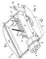
- Fig. 1 shows a general designated 1 terminal box, the one Bottom part 2, a circuit board 3 and a protective cover 4 comprises.
- the Printed circuit board 3 contains various electrical and electronic control and functional parts 5 for controlling a (not shown) The electric motor.
- the printed circuit board 3 is in the finished Bottom part 2 used, after which the protective cover 4 with the bottom part is connected by positive locking or by screw connection.
- the bottom part 2 has a connector strip 6 on its motor side, with which the terminal box 1 is plugged onto the electric motor for this purpose in a known manner has a plug receptacle around the stator of the motor to be connected electrically.
- the electric motor in particular used to drive a heating pump (not shown).
- the plastic base part 2 has at least one set A.
- Plug-in contact parts which form connecting terminals and on the one hand with the PCB 3 are in electrical contact and on the other hand up to Extension strip 6 extend in which their ends for executing the plug connection open freely with the electric motor (Fig. 4).
- the base part 2 has an inside stabilizing bar 7 on, in which the plug contact parts A with their inner portion in are essentially embedded and thus protected against bending.
- the bottom part 2 is not shown as such to the shape all plug-in contact parts and other contact parts, such as those in the base part are cast in, to be able to recognize better.
- connection with the 3 and 4 is clear how the location and the course of all contact parts in the cast bottom part 2.
- FIG. 2 From Fig. 2 it can be seen how the plug contact parts A are shaped and later held in position in the bottom part 2. In Fig. 2 are in addition to the plug contact parts A also other, explained below Contact parts in their shape and later fixed positioning shown in the bottom part.
- the bottom part 2 is made of plastic and is produced by injection molding.
- the injection mold for the base part is designed so that the plug contact parts A and the other contact parts shown in Fig. 2 before injection molding into the mold in the intended position being held.
- the liquid casting material is provided with contact parts and is ready for casting injected from plastic, which is in the mold Body shape of the bottom part 2 forms and thereby all plug contact parts at the same time A and the other contact parts as well as other parts according to Fig. 2 are poured directly into the bottom part.
- the Plug-in contact parts A in the base part 2 at least with its central section 8 poured directly.
- the bottom part shows an outer header 6 and an inner stabilizer bar 7 for Plug contact parts A on.
- the plug contact parts A punch out from a circuit board in such a way that that at least at the edge at least one metal holding strip remains for the contact parts, after which a bending shape of the punched plug contact parts can be made.
- the contact parts then become a common plastic holding strip cast on, which holds all contact parts prepositioned to each other.
- the metal holding strip is punched out so that a prefabricated plug contact structure is obtained.
- This structure will then alternatively inserted into the mold for the bottom part. After that is done pouring the pre-positioned plug contact parts A into the bottom part by pouring the same, whereby the plug contact parts indirectly in are cast in the bottom part.
- the plug contact parts B there is an additional set B of plug contact parts provided for the bottom part 2.
- the bottom part has a molded protective sleeve 9, in which the protrude into the bottom part of the plug-in contact parts B as it protrudes 1 and 3 can be seen.
- the protective sleeve 9 with the plug contact parts B thus forms a further plug-in area of the terminal box.
- the plug contact parts B can also indirectly in the Be cast in the bottom part, i.e. with the help of a pre-cast and prepositioning Retaining strip made of plastic.
- one of the additional plug contact parts B is a grounding element 10 with which the electrical grounding of the connected Electric motor is effected.
- This grounding element points a portion 11 molded in the molded material of the bottom part with a hole 12 on.
- the section 11 of the grounding element is however shaped and cast in the bottom part so that this section exposed to the cast bottom wall of the bottom part Has contact surface 13.
- This contact surface comes later when assembling the terminal box on the electric motor directly or indirectly with its housing in electrical contact, advantageously by direct Investment.
- a screw is used, which advantageously the hole 12 engages in section 11 and the contact surface 13 against the motor housing suppressed.
- a temperature sensing element 14 is cast in the bottom part.
- the element 14 With its lower section 15, the element 14 is in the bottom wall of the bottom part 2 cast directly.
- This section can at least have an extension 16 which in the inner stabilizing bar 7 of Bottom part 2 is cast in to the temperature sensing element to anchor more securely in the bottom part.
- the lower section 15 is also so shaped and poured into the bottom wall of the bottom part, that an exposed contact surface opposite the cast bottom wall 17 is provided.
- This contact surface is also advantageous directly on the housing of the electric motor with the terminal box attached 1 to the facility.
- the temperature sensing element 14 has an upper section 19 with, for example, two plug ends 20. As from FIGS. 1 and 3 can be seen is the section extending into the interior of the bottom part 19 of the element 14 essentially embedded in a holding rib 21, which is also cast when casting the bottom part 2.
- the free ones are located Ends 25 of the plug contact parts A, the free ends 24 of the plug contact parts B and the free ends 20 of the temperature sensing element 14 in one common level. According to the position of these free ends Provide the circuit board with corresponding holes 26 and 27, so that the Assembled circuit board on the free ends 20, 24 in one operation and 25 can be attached. If the control parts 5 and other functional parts the circuit board 3 already with the associated routes of PCB should be electrically connected, in the end only nor the ends 25 and 24 inserted into the holes 26 in the printed circuit board the plug contact parts A and B electrically connected to each other, for. B. by soldering or using an electrically conductive adhesive.
- the free ends 20 of the temperature sensing element 14 protrude through Holes 27 of the circuit board 3, but they are not with this circuit board conductively connected, but isolated from this. They are thermally conductive with a temperature sensor mounted on the circuit board 3 (not shown) connected, which in turn with the control parts 5 of the circuit board interacts to generate a switching pulse to the terminal box 1 to be provided electric motor.
- the above embodiment is in connection with an equipped PCB 3 described.
- the terminal box can be modified 1 but can also be used without a printed circuit board.
- the electrical control parts 5 and other functional parts if desired, arranged in a conventional manner in the bottom part and fastened and with the cast-in electrical plug contact parts A, B electrically connected.
Landscapes
- Engineering & Computer Science (AREA)
- Power Engineering (AREA)
- Manufacturing & Machinery (AREA)
- Microelectronics & Electronic Packaging (AREA)
- Motor Or Generator Frames (AREA)
- Connector Housings Or Holding Contact Members (AREA)
- Structures Of Non-Positive Displacement Pumps (AREA)
- Details Of Reciprocating Pumps (AREA)
Description
- Fig. 1
- eine auseinandergezogene Perspektivansicht des Ausführungsbeispiels,
- Fig. 2
- eine Perspektivansicht von bestimmungsgemäß geformten und positionierten Kontaktteilen, die jedoch noch nicht eingegossen sind,
- Fig. 3
- eine Perspektivansicht des Bodenteils des Klemmenkastens, wobei die Kontaktteile in dem Bodenteil unmittelbar eingegossen sind,
- Fig. 4
- einen Querschnitt durch das Bodenteil mit eingegossenen Steckkontaktteilen nach der Linie IV - IV in Fig. 3.
Claims (10)
- Steckbarer Klemmenkasten zum elektrischen Anschluss an einen insbesondere für eine Heizungspumpe bestimmten Elektromotor, umfassenddadurch gekennzeichnet, dass alle Steckkontaktteile (A) des Steckbereiches durch den Vorgang des Gießens des Bodenteils (2) in diesem Bodenteil ortsfest eingebettet sind.ein aus Kunststoff bestehendes Bodenteil mit mindestens einem Steckbereich, der elektrische Steckkontaktteile als Anschlußklemmen aufweist, die mit ihrem äußeren Steckabschnitt in elektrische Gegensteckkontaktteile des Elektromotors steckbar sind,in dem Bodenteil vorgesehene elektrische Steuerteile für die Steuerung des Elektromotorsund einen mit dem Bodenteil verbundenen Schutzdeckel für alle Steuerteile in dem Klemmenkasten,
- Klemmenkasten nach Anspruch 1, dadurch gekennzeichnet, dass das Bodenteil (2) in seinem motorseitigen Steckbereich eine aussenseitige, mitgegossene Steckleiste (6) aufweist, in welcher der äußere Abschnitt der Steckkontaktteile (A) teilweise eingegossen ist.
- Klemmenkasten nach Anspruch 1 oder 2, dadurch gekennzeichnet, dass das Bodenteil (2) eine innenseitige, mitgegossene Stabilisierungsleiste (7) aufweist, in welcher der innere Abschnitt der Steckkontaktteile (A) teilweise eingegeossen ist.
- Klemmkasten nach Anspruch 1, 2 oder 3, dadurch gekennzeichnet, dass das Bodenteil (2) zum elektrischen Anschluss des Klemmenkastens ( 1 ) an ein Versorgungsstromnetz einen weiteren Steckbereich mit zusätzlichen Steckkontaktteilen (B) aufweist, die alle einerseits in der Wand dieses Steckbereiches eingegossen sind und andererseits zum Anschließen eines Steckelementes eines Netzkabels aus dem Bodenteil herausragen.
- Klemmenkasten nach Anspruch 4, dadurch gekennzeichnet, dass eines der zusätzlichen Steckkontaktteile (B) ein Erdungselement (10) ist, das derart in dem Bodenteil (2) eingegossen ist, dass es eine gegenüber der gegossenen Bodenwand des Bodenteils freiliegende Kontaktfläche (13) aufweist, die beim Anbringen des Klemmenkastens (1) an dem Elektromotor mit dessen Gehäuse in leitende Verbindung gelangt.
- Klemmenkasten nach einem der vorstehenden Ansprüche, dadurch gekennzeichnet, dass in der Bodenwand des Bodenteils (2) ein Temperaturfühlelement (14) derart eingegossen ist, dass es einerseits eine gegenüber der gegossenen Bodenwand freiliegende Kontaktfläche (17) aufweist, die beim Anbringen des Klemmenkastens (1) an dem Elektromotor mit dessen Gehäuse in Kontakt kommt, und sich andererseits in das Innere des Bodenteils (2) erstreckt.
- Klemmenkasten nach Anspruch 6, dadurch gekennzeichnet, dass der sich in das Innere des Bodenteils (2) erstreckende Abschnitt (19) des Temperaturfühlelementes (14) im Wesentlichen in einer mitgegossenen Halterippe (21) eingebettet ist.
- Klemmenkasten nach einem der Ansprüche 1 bis 5, dadurch gekennzeichnet, dass alle aus dem Bodenteil nach außen herausragenden Steckkontaktteile (A, B) jedes Steckbereiches jeweils eine Gruppe bilden und dass die beiden Gruppen je von einer angegossenen Schutzhülse (9, 23) umgeben sind.
- Klemmenkasten nach einem der vorstehenden Ansprüche, dadurch gekennzeichnet, dass die inneren Enden (24, 25, 20) sämtlicher stromleitender Steckkontaktteile (A, B) und des Temperaturfühlelementes (14) in einer Ebene vorgesehen und steckbar ausgebildet sind, dass eine Leiterplatte (3) vorgesehen ist, auf der die elektischen Steuerteile (5) angeordnet sind und die Löcher (26, 27) zur Aufnahme dieser steckbaren Enden aufweist und dass die darin eingesteckten Enden sämtlicher eingegossenen Steckkontaktteile (A, B) mit der Leiterplatte (3) elektrisch verbunden sind.
- Klemmenkasten nach einem der Ansprüche 1 bis 8, dadurch gekennzeichnet, dass die inneren Enden (24, 25, 20) sämtlicher stromleitender Steckkontaktteile (A, B) und des Temperaturfühlelementes (14) in einer Ebene vorgesehen und steckbar ausgebildet sind, dass eine Leiterplatte (3) vorgesehen ist, auf der die elektrischen Steuerteile (5) angeordnet sind und die Löcher (26, 27) zur Aufnahme dieser steckbaren Enden aufweist und dass die darin eingesteckten Enden sämtlicher eingegossenen Steckkontaktteile (A, B) sowie die elektrischen Steuerteile (5) der Leiterplatte (3) mit der letzteren durch einen einzigen elektrischen Verbindungsvorgang verbunden sind.
Applications Claiming Priority (2)
| Application Number | Priority Date | Filing Date | Title |
|---|---|---|---|
| DE10005505.2A DE10005505B4 (de) | 2000-02-08 | 2000-02-08 | Heizungspumpe |
| DE10005505 | 2000-02-08 |
Publications (4)
| Publication Number | Publication Date |
|---|---|
| EP1133012A2 EP1133012A2 (de) | 2001-09-12 |
| EP1133012A3 EP1133012A3 (de) | 2002-05-29 |
| EP1133012B1 true EP1133012B1 (de) | 2003-06-04 |
| EP1133012B2 EP1133012B2 (de) | 2016-11-30 |
Family
ID=7630208
Family Applications (1)
| Application Number | Title | Priority Date | Filing Date |
|---|---|---|---|
| EP01102297.7A Expired - Lifetime EP1133012B2 (de) | 2000-02-08 | 2001-02-01 | Steckbarer Klemmenkasten |
Country Status (2)
| Country | Link |
|---|---|
| EP (1) | EP1133012B2 (de) |
| DE (2) | DE10005505B4 (de) |
Families Citing this family (16)
| Publication number | Priority date | Publication date | Assignee | Title |
|---|---|---|---|---|
| JP3868796B2 (ja) * | 2001-11-07 | 2007-01-17 | アルプス電気株式会社 | 電気部品 |
| DE50304462D1 (de) * | 2003-03-21 | 2006-09-14 | Grundfos As | Pumpenaggregat |
| WO2008019818A1 (de) * | 2006-08-14 | 2008-02-21 | Grundfos Management A/S | Statoranordnung für ein pumpenaggregat |
| ATE505651T1 (de) * | 2007-01-18 | 2011-04-15 | Grundfos Management As | Pumpenaggregat |
| DE102011002933A1 (de) * | 2011-01-20 | 2012-07-26 | Siemens Aktiengesellschaft | Stator einer elektrischen Maschine mit einem Kontaktierelement |
| DE102011079377A1 (de) * | 2011-07-19 | 2013-01-24 | Robert Bosch Gmbh | Steckermodul, insbesondere für Fensterheberantriebe, sowie Verfahren zu dessen Herstellung |
| EP2589817B1 (de) * | 2011-11-07 | 2017-12-13 | Grundfos Holding A/S | Pumpenaggregat |
| EP2610500B1 (de) | 2011-12-27 | 2015-09-16 | Grundfos Holding A/S | Pumpenaggregat |
| FR2992794B1 (fr) | 2012-06-29 | 2014-08-08 | Leroy Somer Moteurs | Machine electrique tournante equipee d'une boite a bornes. |
| PL2750265T4 (pl) * | 2012-12-27 | 2018-07-31 | Grundfos Holding A/S | Agregat pompowy |
| DE102015119002A1 (de) * | 2015-11-05 | 2017-05-11 | Ebm-Papst Mulfingen Gmbh & Co. Kg | Elektronikeinheit |
| DE102017112810A1 (de) | 2017-06-09 | 2018-12-13 | Hefei Xinhu Canned Motor Pump Co.,Ltd | Stator-Anschlusskasten-Einheit für eine elektrisch angetriebene Umwälzpumpe |
| DE102018210892B4 (de) * | 2018-07-03 | 2025-08-07 | Bayerische Motoren Werke Aktiengesellschaft | Steckverbindungselement für ein Kraftfahrzeug und Verfahren zum Herstellen eines solchen Steckverbindungselements |
| DE102019117834A1 (de) * | 2019-07-02 | 2021-01-07 | Kolektor Group D.O.O. | Elektrische oder elektronische Baugruppe sowie Verfahren zur Herstellung eines elektrischen oder elektronischen Bauteils |
| DE102021118958A1 (de) * | 2021-07-22 | 2023-01-26 | KSB SE & Co. KGaA | Pumpe mit am Motorgehäuse montiertem Elektronikgehäuse |
| DE102023207808A1 (de) * | 2023-08-14 | 2025-02-20 | Robert Bosch Gesellschaft mit beschränkter Haftung | Elektromotorische Antriebseinheit |
Family Cites Families (11)
| Publication number | Priority date | Publication date | Assignee | Title |
|---|---|---|---|---|
| DE2264146A1 (de) * | 1972-12-29 | 1974-07-11 | Siemens Ag | Kontaktleiste, insbesondere steckkontaktmesserleiste fuer elektrische anlagen |
| US4642885A (en) * | 1984-02-15 | 1987-02-17 | General Electric Company | Method of assembling a stator |
| US4656378A (en) * | 1985-11-12 | 1987-04-07 | Amp Incorporated | Motor stator and connector for making connections to stator windings |
| JPH066689Y2 (ja) * | 1987-10-21 | 1994-02-16 | 三菱電機株式会社 | 小型電動機 |
| DE3743168A1 (de) * | 1987-12-19 | 1989-06-29 | Oplaender Wilo Werk Gmbh | Elektromotor einer kreiselpumpe |
| DE3803164A1 (de) * | 1988-02-03 | 1989-08-17 | Ruetschi Ag Pumpenbau K | Anschluss- und schalteinrichtung fuer einen elektromotor |
| JP2598130B2 (ja) * | 1989-05-24 | 1997-04-09 | ファナック株式会社 | 一体成形コネクタを有したモータの構造 |
| DE9315914U1 (de) * | 1993-10-19 | 1993-12-23 | Grundfos A/S, Bjerringbro | Steckkontaktsatz für eine steckbare elektrische Anschlußeinrichtung für den Elektromotor einer Heizungspumpe |
| FR2719875B1 (fr) * | 1994-05-10 | 1996-07-12 | Rena France | Perfectionnement pour moteur de pompe hydraulique. |
| JPH10272650A (ja) * | 1997-03-31 | 1998-10-13 | Sumitomo Wiring Syst Ltd | コネクタ付きインサート成形品及びその製造方法 |
| DE19851455A1 (de) | 1998-02-05 | 1999-08-12 | Bosch Gmbh Robert | Elektronikmodul für eine elektromotorisch betriebene Antriebseinheit |
-
2000
- 2000-02-08 DE DE10005505.2A patent/DE10005505B4/de not_active Expired - Lifetime
-
2001
- 2001-02-01 DE DE50100273T patent/DE50100273D1/de not_active Expired - Lifetime
- 2001-02-01 EP EP01102297.7A patent/EP1133012B2/de not_active Expired - Lifetime
Also Published As
| Publication number | Publication date |
|---|---|
| DE50100273D1 (de) | 2003-07-10 |
| EP1133012A3 (de) | 2002-05-29 |
| EP1133012B2 (de) | 2016-11-30 |
| EP1133012A2 (de) | 2001-09-12 |
| DE10005505B4 (de) | 2019-03-28 |
| DE10005505A1 (de) | 2001-08-16 |
Similar Documents
| Publication | Publication Date | Title |
|---|---|---|
| EP1133012B1 (de) | Steckbarer Klemmenkasten | |
| DE69019307T2 (de) | Aufbau eines motorgehäuses mit integriert angegossenem elektrischem anschluss. | |
| DE60206541T2 (de) | Anschlussverbindungsanordnung | |
| EP0717588B1 (de) | Gehäuse für ein elektrisches Bauteil | |
| DE10329843A1 (de) | Verfahren zum wasserdichten Abdichten eines Leistungsschaltkreisabschnittes und Leistungsmodul mit einem derartigen Leistungsschaltkreisabschnitt | |
| EP1199913B1 (de) | Verfahren zur Herstellung von Leiterfolie-Trägergehäuse-Einheiten | |
| DE102008062561A1 (de) | Bausatz für einen Elektromotor mit einem Drehwinkelgeber | |
| DE19723664A1 (de) | Steuereinheit für einen Elektromotor | |
| EP2351059B1 (de) | Komponententräger für im wesentlichen elektrische bauelemente | |
| DE3822533A1 (de) | Verfahren zur herstellung einer temperaturfuehler-vorrichtung und nach dem verfahren hergestellte fuehlervorrichtung | |
| WO2004103044A1 (de) | Komponententräger | |
| EP1357774A1 (de) | Verfahren zum Herstellen einer kunststoffumspritzen Leiterstruktur sowie elektrische Schaltungseinheit mit einer kunststoffumspritzten Leiterstruktur | |
| EP0982978A2 (de) | Gehäuse, insbesondere Schlossgehäuse mit elektrischen Anschlusseinrichtungen | |
| EP1170110A1 (de) | Verfahren zum Herstellen einer kunststoffumspritzten Leiterstruktur einer elektrischen Schaltungseinheit sowie eine elektrische Schaltungseinheit mit einer kunststoffumspritzten Leiterstruktur | |
| EP0105392A2 (de) | Kasten-Bürstenhalter für einen Elektro-Kommutatormotor | |
| DE4110474A1 (de) | Elektromotor | |
| DE68910252T2 (de) | Gehäuse für elektronische Schaltungen, insbesondere für Kraftfahrzeuge. | |
| EP3221935B1 (de) | Elektrische verbindungsanordnung und verfahren zu deren herstellung | |
| WO2000002431A2 (de) | Gehäuse für eine elektronik-einheit, insbesondere für ein airbag-steuergerät | |
| EP1502324B1 (de) | Steckerbr cke mit hohlstift | |
| DE3205714A1 (de) | Zuendanlage fuer brennkraftmaschinen | |
| EP1164687B1 (de) | Verfahren zum Herstellen eines Gehäusebodenteils eines aufsteckbaren Klemmenkastens für einen Elektromotor | |
| EP0696881A1 (de) | Kunststoffgehäuse für ein elektrisches Modul | |
| DE10320441B3 (de) | Komponententräger | |
| DE19733237C1 (de) | Elektrisches Gerät |
Legal Events
| Date | Code | Title | Description |
|---|---|---|---|
| PUAI | Public reference made under article 153(3) epc to a published international application that has entered the european phase |
Free format text: ORIGINAL CODE: 0009012 |
|
| AK | Designated contracting states |
Kind code of ref document: A2 Designated state(s): AT BE CH CY DE DK ES FI FR GB GR IE IT LI LU MC NL PT SE TR |
|
| AX | Request for extension of the european patent |
Free format text: AL;LT;LV;MK;RO;SI |
|
| PUAL | Search report despatched |
Free format text: ORIGINAL CODE: 0009013 |
|
| AK | Designated contracting states |
Kind code of ref document: A3 Designated state(s): AT BE CH CY DE DK ES FI FR GB GR IE IT LI LU MC NL PT SE TR |
|
| AX | Request for extension of the european patent |
Free format text: AL;LT;LV;MK;RO;SI |
|
| RIC1 | Information provided on ipc code assigned before grant |
Free format text: 7H 01R 13/115 A, 7H 01R 13/504 B, 7H 01R 43/24 B, 7H 02K 5/22 B |
|
| GRAH | Despatch of communication of intention to grant a patent |
Free format text: ORIGINAL CODE: EPIDOS IGRA |
|
| 17P | Request for examination filed |
Effective date: 20020830 |
|
| AKX | Designation fees paid |
Designated state(s): DE FR GB IT |
|
| GRAH | Despatch of communication of intention to grant a patent |
Free format text: ORIGINAL CODE: EPIDOS IGRA |
|
| GRAA | (expected) grant |
Free format text: ORIGINAL CODE: 0009210 |
|
| AK | Designated contracting states |
Designated state(s): DE FR GB IT |
|
| REG | Reference to a national code |
Ref country code: GB Ref legal event code: FG4D Free format text: NOT ENGLISH |
|
| REG | Reference to a national code |
Ref country code: IE Ref legal event code: FG4D Free format text: GERMAN |
|
| REF | Corresponds to: |
Ref document number: 50100273 Country of ref document: DE Date of ref document: 20030710 Kind code of ref document: P |
|
| GBT | Gb: translation of ep patent filed (gb section 77(6)(a)/1977) |
Effective date: 20031020 |
|
| REG | Reference to a national code |
Ref country code: IE Ref legal event code: FD4D |
|
| PLBI | Opposition filed |
Free format text: ORIGINAL CODE: 0009260 |
|
| PLBQ | Unpublished change to opponent data |
Free format text: ORIGINAL CODE: EPIDOS OPPO |
|
| PLAX | Notice of opposition and request to file observation + time limit sent |
Free format text: ORIGINAL CODE: EPIDOSNOBS2 |
|
| ET | Fr: translation filed | ||
| 26 | Opposition filed |
Opponent name: WILO AG Effective date: 20040226 |
|
| PLAX | Notice of opposition and request to file observation + time limit sent |
Free format text: ORIGINAL CODE: EPIDOSNOBS2 |
|
| PLBB | Reply of patent proprietor to notice(s) of opposition received |
Free format text: ORIGINAL CODE: EPIDOSNOBS3 |
|
| APBM | Appeal reference recorded |
Free format text: ORIGINAL CODE: EPIDOSNREFNO |
|
| APBP | Date of receipt of notice of appeal recorded |
Free format text: ORIGINAL CODE: EPIDOSNNOA2O |
|
| APAH | Appeal reference modified |
Free format text: ORIGINAL CODE: EPIDOSCREFNO |
|
| APBM | Appeal reference recorded |
Free format text: ORIGINAL CODE: EPIDOSNREFNO |
|
| APBP | Date of receipt of notice of appeal recorded |
Free format text: ORIGINAL CODE: EPIDOSNNOA2O |
|
| APBQ | Date of receipt of statement of grounds of appeal recorded |
Free format text: ORIGINAL CODE: EPIDOSNNOA3O |
|
| REG | Reference to a national code |
Ref country code: FR Ref legal event code: PLFP Year of fee payment: 16 |
|
| APBU | Appeal procedure closed |
Free format text: ORIGINAL CODE: EPIDOSNNOA9O |
|
| PUAH | Patent maintained in amended form |
Free format text: ORIGINAL CODE: 0009272 |
|
| STAA | Information on the status of an ep patent application or granted ep patent |
Free format text: STATUS: PATENT MAINTAINED AS AMENDED |
|
| 27A | Patent maintained in amended form |
Effective date: 20161130 |
|
| AK | Designated contracting states |
Kind code of ref document: B2 Designated state(s): DE FR GB IT |
|
| REG | Reference to a national code |
Ref country code: DE Ref legal event code: R102 Ref document number: 50100273 Country of ref document: DE |
|
| REG | Reference to a national code |
Ref country code: FR Ref legal event code: PLFP Year of fee payment: 17 |
|
| REG | Reference to a national code |
Ref country code: FR Ref legal event code: PLFP Year of fee payment: 18 |
|
| PGFP | Annual fee paid to national office [announced via postgrant information from national office to epo] |
Ref country code: GB Payment date: 20200225 Year of fee payment: 20 Ref country code: IT Payment date: 20200221 Year of fee payment: 20 Ref country code: DE Payment date: 20200226 Year of fee payment: 20 |
|
| PGFP | Annual fee paid to national office [announced via postgrant information from national office to epo] |
Ref country code: FR Payment date: 20200220 Year of fee payment: 20 |
|
| REG | Reference to a national code |
Ref country code: DE Ref legal event code: R071 Ref document number: 50100273 Country of ref document: DE |
|
| REG | Reference to a national code |
Ref country code: GB Ref legal event code: PE20 Expiry date: 20210131 |
|
| PG25 | Lapsed in a contracting state [announced via postgrant information from national office to epo] |
Ref country code: GB Free format text: LAPSE BECAUSE OF EXPIRATION OF PROTECTION Effective date: 20210131 |