EP1133018A2 - Anti-decoupling arrangement for an electrical connector - Google Patents
Anti-decoupling arrangement for an electrical connector Download PDFInfo
- Publication number
- EP1133018A2 EP1133018A2 EP01300351A EP01300351A EP1133018A2 EP 1133018 A2 EP1133018 A2 EP 1133018A2 EP 01300351 A EP01300351 A EP 01300351A EP 01300351 A EP01300351 A EP 01300351A EP 1133018 A2 EP1133018 A2 EP 1133018A2
- Authority
- EP
- European Patent Office
- Prior art keywords
- spring ring
- spiral lock
- coupling nut
- lock clutch
- decoupling
- Prior art date
- Legal status (The legal status is an assumption and is not a legal conclusion. Google has not performed a legal analysis and makes no representation as to the accuracy of the status listed.)
- Granted
Links
Images

Classifications
-
- H—ELECTRICITY
- H01—ELECTRIC ELEMENTS
- H01R—ELECTRICALLY-CONDUCTIVE CONNECTIONS; STRUCTURAL ASSOCIATIONS OF A PLURALITY OF MUTUALLY-INSULATED ELECTRICAL CONNECTING ELEMENTS; COUPLING DEVICES; CURRENT COLLECTORS
- H01R13/00—Details of coupling devices of the kinds covered by groups H01R12/70 or H01R24/00 - H01R33/00
- H01R13/62—Means for facilitating engagement or disengagement of coupling parts or for holding them in engagement
- H01R13/622—Screw-ring or screw-casing
Definitions
- the present invention generally relates to anti-decoupling arrangements for connectors of the type in which coupling is achieved by means of a coupling nut, and more particularly to an anti-decoupling arrangement for an electrical connector that uses a ratchet mechanism to limit rotation of the coupling nut in the decoupling direction and a spiral lock clutch to permit free rotation of the coupling nut in the coupling direction. Still more particularly, the invention relates to improvements on the anti-decoupling arrangement disclosed in copending U.S. Patent Application Ser. No. 09/391,458, filed September 8, 1999, incorporated by reference herein.
- a typical connector to which the present invention may be applied includes a connector shell containing electrical contacts and an internally threaded coupling nut rotatably mounted on the connector shell.
- the connector shell is coupled to a corresponding externally threaded mating connector by means of the coupling nut in such a manner that electrical contacts in the mating connector engage the electrical contacts in the connector shell.
- the coupling nut is held on the connector shell by one or more retaining rings and/or spring washers that are designed to captivate or press a radial flange of the coupling nut against a corresponding flange or shoulder on the connector shell.
- the simplest and most common method of preventing unintended decoupling as a result of shocks or vibrations has been to include in the connector a metal ratchet spring having protrusions or dimples at the center of the beam, the ratchet spring being permanently attached to the inside diameter of the threaded coupling nut.
- the connector shell is provided with ratchet teeth on its outer diameter, which are engaged by the ratchet spring.
- the tooth wheel includes extensions or knurls that cooperate with corresponding slots or surfaces of the coupling nut to prevent relative rotation between the coupling nut and the tooth wheel, while the spring ring includes spring tines that engage radial cuts in the tooth wheel to permit ratcheting of the tooth wheel relative to the spring ring.
- the spring ring in turn, is locked against rotation relative to the spiral lock clutch.
- turning of the coupling nut causes corresponding turning of the tooth wheel. Since the spiral lock clutch is arranged to unwind and permit free running in the coupling direction, the engagement between the spring tines on the spring ring and the radial cuts is not subject to any ratcheting force and the spring ring and spiral lock clutch turn freely with the coupling nut and tooth wheel.
- the spiral lock clutch winds tightly against the connector shell, preventing rotation of the spiral lock clutch and spring ring.
- a sufficient force must be applied to the coupling nut to permit ratcheting of the spring ring relative to the tooth wheel, i . e ., to permit the spring tines to glide over the teeth formed by the radial cuts in the ratchet wheel.
- the above-described anti-decoupling arrangement has the advantages, relative to the anti-decoupling arrangement described in U.S. Patent No. 4,536,048, of attaining a high uncoupling torque due to the use of multiple tines or beams on the spring ring attached to the spiral lock clutch, control of the coupling torque through appropriate choice of the spiral lock clutch, spring tines, and tooth configuration, and simplified assembly to the connector shell by fitting all of the components over the shell, angularly orienting the components, and holding them in place with a retaining ring. Nevertheless, the above-described anti-decoupling mechanism still could benefit from the following improvements:
- an anti-decoupling arrangement for an electrical connector (as well as an electrical connector incorporating such an anti-decoupling arrangement) which consists of just three operative components: a spiral lock clutch, at least one spring ring, and ratchet teeth or serrations formed on an inside surface of the coupling nut.
- the ratchet teeth are in the form of serrations formed into the inside diameter of a recessed area of the coupling nut in which all of the components reside, and each spring ring is a self-supporting ring that has spring cantilevers with engaging tines of a given number located around its outer circumference, the engaging tines engaging the serrations in a radial direction.
- the engaging tines thus provide a torque/ratchet mechanism when they glide over the radial cuts of the tooth ring in the uncoupling direction.
- the coupling nut may be assembled to the shell so that it bottoms out shoulder to shoulder, and subsequently the spiral clutch band is assembled onto the shell at a position spaced from but near a shoulder extending from the shell. If a groove is provided, the clutch band may be assembled in the groove.
- a tapered shaft is fitted over the rear of the plug shell to temporarily enlarge the spiral lock clutch band, allowing it to slide over the rear of the shell and down into the first groove.
- the spring ring or rings are then assembled onto the spiral lock clutch by aligning respective complementary interengaging structures on the spring ring or rings and on the spiral lock clutch band, the complementary interengaging structures including, by way of example and not limitation, a slot in each spring ring and a small hook like bend on the end of the spiral lock clutch band.
- the order of assembly may be varied within the scope of the invention, for example, by first assembling the spring ring or rings to the plug shell, and then assembling the clutch.
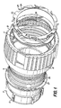
- Fig. 1 is an isometric view showing an electrical connector anti-decoupling arrangement constructed in accordance with the principles of a preferred embodiment of the invention.
- Fig. 2 is a cross-sectional side view of the electrical connector and anti-decoupling arrangement of Fig. 1.
- Fig. 3 is an isometric view showing details of a coupling nut for use in the anti-decoupling arrangement of the preferred embodiment.
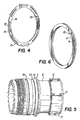
- Fig. 4 is an isometric view showing details of a spring ring for use in the anti-decoupling arrangement of the preferred embodiment.
- Fig. 5 is an isometric view showing details of a plug shell for use with the anti-decoupling arrangement of the preferred embodiment.
- Fig. 6 is an isometric view showing details of a spiral lock clutch for use in the anti-decoupling arrangement of the preferred embodiment.
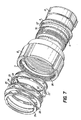
- Fig. 7 is an isometric view showing an electrical connector anti-decoupling arrangement constructed in accordance with the principles of a second preferred embodiment of the invention.
- a connector having an anti-decoupling mechanism constructed in accordance with the principles of a preferred embodiment of the invention includes a plug connector shell 8 having a front mating section corresponding to the one illustrated in U.S. Patent No. 4,536,048, incorporated herein by reference. Between the front and rear section of the plug connector shell 8 is a flange or shoulder 9 having a rear surface 10 which faces a collar or flange 11 extending radially inwardly from the coupling nut 12.
- the illustrated connector shell 8 and coupling nut 12 have the general configuration of a type of connector known as the "Series III" connector, including such features as polarizing keys 13, and a standard Tri-start thread 14 on the coupling nut 12.
- Series III a type of connector known as the "Series III" connector
- the anti-decoupling arrangement of the preferred embodiment is especially suitable for use in the Series III connector, which is designed to be used in harsh environments (the standards therefor being specified in standard shell sizes 9-25 according to MIL-C-38999/26D, dated May 7, 1990), those skilled in the art will appreciate that the principles of the invention are not limited to Series III connectors, but rather are applicable to any cylindrical connectors having threaded couplings and a need for an anti-decoupling arrangement.
- Spiral lock clutch 19 is preferably in the form of a wound radial spring band surrounding the shell 13.
- the spiral lock clutch may be loosely captured in a groove 27 situated rearwardly of flange 9, although it is also within the scope of the invention to omit groove 27, and includes a small hook like bend or tab 20 extending from one end 21 of the band in a transverse direction relative to the principal plane of the band so as to project rearwardly of the band when the band is assembled to the plug shell 8.
- Tab 20 is arranged to engage a slot 22 extending from an inside diameter of a spring ring 23 such that when the spring ring 23 is fitted onto the plug connector shell 8 and oriented so that slot 22 aligns with tab 20, spring ring 23 and end 21 of the band are thereby locked against relative rotational movement.
- spiral lock clutch 19 may be similar to the spiral ring disclosed in the above-cited copending U.S. Patent Application Ser. No. 09/391,458.
- clutch 19 and ring 23 are locked together against relative rotational movement may take a variety of forms, such as a tab on clutch 19 and a slot, notch, or groove situated away from the inside diameter of the spring ring 23, a slot in the clutch and tab on the spring ring, a weld joint, or any other suitable joining structure.
- Spring ring 23 includes, in addition to slot 22, a plurality of spring tines or beams 24 arranged to flex in a radial direction, as shown in Fig. 4.
- Spring beams 24 include, at their distal ends, radially outwardly extending angled sections or detents 25 arranged to cooperate with corresponding serrations 26 formed into the inside surface of coupling nut 12 to provide a ratcheting effect, as described below, when the spring ring 23 is fitted over plug shell 8 such that the serrations surround the spring ring.
- spring ring 23 of the preferred embodiment is completely planar in construction and therefore can be more easily manufactured.
- the planar construction and radial engagement of beams 24 with serrations 26 permits multiple spring rings 23',23" of the same or different thickness to be stacked upon one another as a way to adjust torque without having to change the design of any of the other components of the anti-decoupling mechanism.
- two spring rings are illustrated, those skilled in the art will appreciate that the number of spring rings may be increased to three or more without departing from the scope of the invention.
- Coupling nut 12 preferably takes the form of a standard coupling nut, with the addition of serrations 26, and is held on the plug shell 8 by a cover ring 28 and standard retaining ring 29 situated in a second groove 30, completing the anti-decoupling mechanism. It will of course be appreciated by those skilled in the art that the combination of a cover ring and retaining ring may be replaced by any suitable retention mechanism, including a non-standard retaining ring that extends outwardly far enough to engage the coupling nut.
- the invention provides for a much greater axial tolerance in positioning the spring ring 23 or rings 23',23" and the spiral lock clutch 19, and a much simpler structure overall, than is possible in the anti-decoupling mechanism described in copending U.S. Patent Application Ser. No.
- the anti-decoupling mechanism ofthe preferred embodiments illustrated in Figs. 1-7 may assembled to the connector, as follows:
- the connector thus assembled operates as follows: When the coupling nut 12 is rotated in the mating or coupling direction, serrations 26 exert a torque on cantilever beams 24 and detents 25, rotating the spring ring 23 or rings 23',23", which in turn rotates the spiral lock clutch 19 in a direction that causes the clutch to unwind from the plug connector shell 8 and freely rotate relative thereto. As a result, the coupling nut can be rotated with a light torque to secure the coupling nut 12 to a mating connector.
- the decoupling torque applied to the coupling nut exceeds a threshold (preferably above the value of any vibration or shock induced torques to which the connector is subject), since the spring ring 23 or rings 23',23" is/are locked against rotation by the spiral lock clutch 19, the serrations 26 are forced to ratchet over the cantilever beams 24, thereby permitting the coupling nut 12 to be decoupled from the corresponding externally threaded portion of the mating connector.
- a threshold preferably above the value of any vibration or shock induced torques to which the connector is subject
- the type of connector to which the decoupling arrangement of the preferred embodiment is applied may be freely modified, as may such details as the nature of the complementary interengaging surfaces between the coupling nut and the plug connector shell ( i . e ., flanges 9 and 11) or the structures that lock the spring ring 23 to the spiral lock clutch 19.
Landscapes
- Details Of Connecting Devices For Male And Female Coupling (AREA)
Abstract
Description
Claims (15)
- An anti-decoupling arrangement arranged to be fitted on a connector shell having a front mating end and a coupling nut fitted over the connector shell, said anti-decoupling arrangement preventing rotation of the coupling nut in a decoupling direction, comprising:a spiral lock clutch extending around said connector shell;at least one spring ring positioned to the rear of the spiral lock clutch, front and rear being hereinafter taken relative to an axis of the connector shell and its front mating end, said spring ring also extending around said connector shell, said spring ring and spiral lock clutch being locked together against relative movement so that the spiral lock clutch rotates with the spring ring, and said spring ring further including cantilever beams, the distal ends of which are formed with radially outwardly extending detents;serrations on an inside surface of said coupling nut, said serrations engaging said detents; andat least one retention member positioned to the rear of the coupling nut to capture the tooth ring, spring ring, spiral lock clutch, and coupling nut and retain them on the connector shell,wherein when said coupling nut is rotated in a coupling direction, said engagement of said cantilever beams with said serrations causes rotation of the spring ring in the coupling direction, the rotation of the spring ring causing rotation of the spiral lock clutch in the coupling direction, said spiral lock clutch being arranged to freely rotate relative to the connector shell and thereby provide minimal resistance to said rotation of the coupling nut in the coupling direction,wherein when a torque less than a threshold value is applied to said coupling nut in a decoupling direction, a corresponding torque is applied by the serrations to the spring ring in the decoupling direction, and said torque applied to the spring ring in the decoupling direction causing said spiral lock clutch to lock and prevent rotation of the spring ring in the decoupling direction, andwherein when a torque greater than a threshold value is applied to the coupling nut in the decoupling direction, said greater torque causes said serrations to ratchet over said detents and thereby permit the coupling nut to be rotated in the decoupling direction despite continued locking of the spiral lock clutch and spring ring against rotation.
- An arrangement as claimed in claim 1, wherein said spiral lock clutch is a wound radial spring band.
- An arrangement as claimed in claim 2, wherein said clutch includes a tab extending transversely from one end of the spiral lock clutch, and said spring ring includes a slot arranged to engage said tab and thereby prevent relative rotation between said spring ring and said clutch.
- An arrangement as claimed in claim 1, wherein said shell is an electrical connector shell.
- An arrangement as claimed in claim 4, wherein said shell is a Series III connector shell.
- An arrangement as claimed in claim 1, wherein said retention member includes a retaining ring and a cover ring arranged to engage said coupling nut.
- An arrangement as claimed in claim 1, further comprising at least one additional spring ring positioned to the rear of the spiral lock clutch and locked together with said first spring ring and clutch against relative movement, said additional spring ring including additional cantilever beams, distal ends of which are formed with radially outwardly extending additional detents, said serrations engaging said additional detents.
- An electrical connector including a connector shell having a front mating end, a coupling nut fitted over the connector shell, and an anti-decoupling arrangement preventing rotation of the coupling nut in a decoupling direction, said anti-decoupling arrangement comprising:a spiral lock clutch extending around said connector shell;at least one spring ring positioned to the rear of the spiral lock clutch, front and rear being hereinafter taken relative to an axis of the connector shell and its front mating end, said spring ring also extending around said connector shell, said spring ring and spiral lock clutch being locked together against relative movement so that the spiral lock clutch rotates with the spring ring, and said spring ring further including cantilever beams, the distal ends of which are formed with radially outwardly extending detents;serrations on an inside surface of said coupling nut, said serrations engaging said detents; andat least one retention member positioned to the rear of the coupling nut to capture the tooth ring, spring ring, spiral lock clutch, and coupling nut and retain them on the connector shell,wherein when said coupling nut is rotated in a coupling direction, said engagement of said cantilever beams with said serrations causes rotation of the spring ring in the coupling direction, the rotation of the spring ring causing rotation of the spiral lock clutch in the coupling direction, said spiral lock clutch being arranged to freely rotate relative to the connector shell and thereby provide minimal resistance to said rotation of the coupling nut in the coupling direction,wherein when a torque less than a threshold value is applied to said coupling nut in a decoupling direction, a corresponding torque is applied by the serrations to the spring ring in the decoupling direction, and said torque applied to the spring ring in the decoupling direction causing said spiral lock clutch to lock and prevent rotation of the spring ring in the decoupling direction, andwherein when a torque greater than a threshold value is applied to the coupling nut in the decoupling direction, said greater torque causes said serrations to ratchet over said detents and thereby permit the coupling nut to be rotated in the decoupling direction despite continued locking of the spiral lock clutch and spring ring against rotation.
- An electrical connector as claimed in claim 8, wherein said spiral lock clutch is a wound radial spring band.
- An electrical connector as claimed in claim 9, wherein said spiral lock clutch is situated in a groove in said connector shell.
- An electrical connector as claimed in claim 8, wherein said clutch includes a tab extending transversely from one end of the spiral lock clutch, and said spring ring includes a slot arranged to engage said tab and thereby prevent relative rotation between said spring ring and said clutch.
- An electrical connector as claimed in claim 8, wherein said shell is an electrical connector shell.
- An electrical connector as claimed in claim 12, wherein said shell is a Series III connector shell.
- An electrical connector as claimed in claim 8, wherein said retention member includes a retaining ring and a cover ring arranged to engage said coupling nut.
- An electrical connector as claimed in claim 8, further comprising at least one additional spring ring positioned to the rear of the spiral lock clutch and locked together with said first spring ring and clutch against relative movement, said additional spring ring including additional cantilever beams, distal ends of which are formed with radially outwardly extending additional detents, said serrations engaging said additional detents.
Applications Claiming Priority (2)
| Application Number | Priority Date | Filing Date | Title |
|---|---|---|---|
| US09/487,214 US6152753A (en) | 2000-01-19 | 2000-01-19 | Anti-decoupling arrangement for an electrical connector |
| US487214 | 2000-01-19 |
Publications (3)
| Publication Number | Publication Date |
|---|---|
| EP1133018A2 true EP1133018A2 (en) | 2001-09-12 |
| EP1133018A3 EP1133018A3 (en) | 2003-01-08 |
| EP1133018B1 EP1133018B1 (en) | 2004-10-06 |
Family
ID=23934835
Family Applications (1)
| Application Number | Title | Priority Date | Filing Date |
|---|---|---|---|
| EP01300351A Expired - Lifetime EP1133018B1 (en) | 2000-01-19 | 2001-01-16 | Anti-decoupling arrangement for an electrical connector |
Country Status (5)
| Country | Link |
|---|---|
| US (1) | US6152753A (en) |
| EP (1) | EP1133018B1 (en) |
| CA (1) | CA2331248C (en) |
| DE (1) | DE60106116T2 (en) |
| IL (1) | IL140800A0 (en) |
Cited By (2)
| Publication number | Priority date | Publication date | Assignee | Title |
|---|---|---|---|---|
| CN101807765A (en) * | 2010-03-24 | 2010-08-18 | 中航光电科技股份有限公司 | Electric connector |
| US9528646B2 (en) | 2014-05-02 | 2016-12-27 | Itt Manufacturing Enterprises, Llc | Locking and ratcheting connector |
Families Citing this family (92)
| Publication number | Priority date | Publication date | Assignee | Title |
|---|---|---|---|---|
| US6666726B2 (en) * | 2000-07-31 | 2003-12-23 | Tru Corporation | Electrical connector assembly |
| US20060110977A1 (en) | 2004-11-24 | 2006-05-25 | Roger Matthews | Connector having conductive member and method of use thereof |
| US8157589B2 (en) | 2004-11-24 | 2012-04-17 | John Mezzalingua Associates, Inc. | Connector having a conductively coated member and method of use thereof |
| US7114990B2 (en) | 2005-01-25 | 2006-10-03 | Corning Gilbert Incorporated | Coaxial cable connector with grounding member |
| US6966788B1 (en) * | 2005-03-15 | 2005-11-22 | Ruhl Jr Harold John | Anti-decoupling mechanism for solid or tubular circular cross section assemblies having a rotating coupling nut or nuts |
| US7128616B1 (en) | 2005-08-15 | 2006-10-31 | Woven Electronics Corporation | High speed data transmission cable connector system |
| US7566236B2 (en) | 2007-06-14 | 2009-07-28 | Thomas & Betts International, Inc. | Constant force coaxial cable connector |
| US9106012B2 (en) * | 2008-05-30 | 2015-08-11 | Itt Manufacturing Enterprises, Inc. | Antirotation coupling for connector |
| US8075337B2 (en) | 2008-09-30 | 2011-12-13 | Belden Inc. | Cable connector |
| US7845963B2 (en) * | 2008-10-21 | 2010-12-07 | Itt Manufacturing Enterprises, Inc. | Axial anti-rotation coupling |
| US7625226B1 (en) | 2008-12-02 | 2009-12-01 | Itt Manufacturing Enterprises, Inc. | Radial anti-rotation coupling |
| US8025518B2 (en) | 2009-02-24 | 2011-09-27 | Corning Gilbert Inc. | Coaxial connector with dual-grip nut |
| US8029315B2 (en) | 2009-04-01 | 2011-10-04 | John Mezzalingua Associates, Inc. | Coaxial cable connector with improved physical and RF sealing |
| US7824216B2 (en) | 2009-04-02 | 2010-11-02 | John Mezzalingua Associates, Inc. | Coaxial cable continuity connector |
| US7892005B2 (en) | 2009-05-19 | 2011-02-22 | John Mezzalingua Associates, Inc. | Click-tight coaxial cable continuity connector |
| US8444445B2 (en) | 2009-05-22 | 2013-05-21 | Ppc Broadband, Inc. | Coaxial cable connector having electrical continuity member |
| US8573996B2 (en) | 2009-05-22 | 2013-11-05 | Ppc Broadband, Inc. | Coaxial cable connector having electrical continuity member |
| US9570845B2 (en) | 2009-05-22 | 2017-02-14 | Ppc Broadband, Inc. | Connector having a continuity member operable in a radial direction |
| US8287320B2 (en) | 2009-05-22 | 2012-10-16 | John Mezzalingua Associates, Inc. | Coaxial cable connector having electrical continuity member |
| US9017101B2 (en) | 2011-03-30 | 2015-04-28 | Ppc Broadband, Inc. | Continuity maintaining biasing member |
| US8070504B2 (en) * | 2009-06-17 | 2011-12-06 | John Mezzalingua Associates, Inc. | Coaxial cable port locking terminator and method of use thereof |
| WO2011006154A1 (en) * | 2009-07-10 | 2011-01-13 | Woodhead Industries, Inc. | High strength electrical connector |
| US20110086543A1 (en) * | 2009-10-09 | 2011-04-14 | Alrutz Mark E | F-Style Coaxial Connectors Having Internally Threaded Nuts that Exhibit Increased Drag and Mechanical Resistance |
| CN102044305B (en) * | 2009-10-12 | 2013-06-05 | 西安威尔罗根能源科技有限公司 | Connecting device for electronic instrument framework and bearing disc |
| US8272893B2 (en) | 2009-11-16 | 2012-09-25 | Corning Gilbert Inc. | Integrally conductive and shielded coaxial cable connector |
| FR2956255B1 (en) * | 2010-02-05 | 2014-08-08 | Souriau | ANTI-UNLOCKING DEVICE FOR CONNECTOR |
| CN101814672B (en) * | 2010-03-24 | 2011-12-21 | 中航光电科技股份有限公司 | Anti-shake connector |
| TWI549386B (en) | 2010-04-13 | 2016-09-11 | 康寧吉伯特公司 | Coaxial connector with inhibited ingress and improved grounding |
| CN101882727B (en) * | 2010-06-30 | 2012-11-28 | 中航光电科技股份有限公司 | Connection-in-place identifiable anti-loose connector |
| US8079860B1 (en) | 2010-07-22 | 2011-12-20 | John Mezzalingua Associates, Inc. | Cable connector having threaded locking collet and nut |
| US8152551B2 (en) | 2010-07-22 | 2012-04-10 | John Mezzalingua Associates, Inc. | Port seizing cable connector nut and assembly |
| US8113879B1 (en) | 2010-07-27 | 2012-02-14 | John Mezzalingua Associates, Inc. | One-piece compression connector body for coaxial cable connector |
| US8888526B2 (en) | 2010-08-10 | 2014-11-18 | Corning Gilbert, Inc. | Coaxial cable connector with radio frequency interference and grounding shield |
| US8025536B1 (en) * | 2010-08-23 | 2011-09-27 | Distinct Intuitive Designs, LLC | Polarized shell for preventing coaxial connector mis-mating |
| US8167636B1 (en) | 2010-10-15 | 2012-05-01 | John Mezzalingua Associates, Inc. | Connector having a continuity member |
| US8167646B1 (en) | 2010-10-18 | 2012-05-01 | John Mezzalingua Associates, Inc. | Connector having electrical continuity about an inner dielectric and method of use thereof |
| US8167635B1 (en) | 2010-10-18 | 2012-05-01 | John Mezzalingua Associates, Inc. | Dielectric sealing member and method of use thereof |
| US8323053B2 (en) | 2010-10-18 | 2012-12-04 | John Mezzalingua Associates, Inc. | Connector having a constant contact nut |
| US8075338B1 (en) | 2010-10-18 | 2011-12-13 | John Mezzalingua Associates, Inc. | Connector having a constant contact post |
| US8172611B1 (en) | 2010-10-26 | 2012-05-08 | John Mezzalingua Associates, Inc. | Method and assembly for connecting a coaxial cable end to a threaded port |
| TWI558022B (en) | 2010-10-27 | 2016-11-11 | 康寧吉伯特公司 | Push-on cable connector with a coupler and retention and release mechanism |
| US8337229B2 (en) | 2010-11-11 | 2012-12-25 | John Mezzalingua Associates, Inc. | Connector having a nut-body continuity element and method of use thereof |
| US8414322B2 (en) | 2010-12-14 | 2013-04-09 | Ppc Broadband, Inc. | Push-on CATV port terminator |
| US8398421B2 (en) | 2011-02-01 | 2013-03-19 | John Mezzalingua Associates, Inc. | Connector having a dielectric seal and method of use thereof |
| US8157588B1 (en) | 2011-02-08 | 2012-04-17 | Belden Inc. | Cable connector with biasing element |
| US8465322B2 (en) | 2011-03-25 | 2013-06-18 | Ppc Broadband, Inc. | Coaxial cable connector |
| US8342879B2 (en) | 2011-03-25 | 2013-01-01 | John Mezzalingua Associates, Inc. | Coaxial cable connector |
| US8366481B2 (en) | 2011-03-30 | 2013-02-05 | John Mezzalingua Associates, Inc. | Continuity maintaining biasing member |
| US8388377B2 (en) | 2011-04-01 | 2013-03-05 | John Mezzalingua Associates, Inc. | Slide actuated coaxial cable connector |
| US8348697B2 (en) | 2011-04-22 | 2013-01-08 | John Mezzalingua Associates, Inc. | Coaxial cable connector having slotted post member |
| WO2012162431A2 (en) | 2011-05-26 | 2012-11-29 | Belden Inc. | Coaxial cable connector with conductive seal |
| US9711917B2 (en) | 2011-05-26 | 2017-07-18 | Ppc Broadband, Inc. | Band spring continuity member for coaxial cable connector |
| US8758050B2 (en) | 2011-06-10 | 2014-06-24 | Hiscock & Barclay LLP | Connector having a coupling member for locking onto a port and maintaining electrical continuity |
| US8591244B2 (en) | 2011-07-08 | 2013-11-26 | Ppc Broadband, Inc. | Cable connector |
| US9190744B2 (en) | 2011-09-14 | 2015-11-17 | Corning Optical Communications Rf Llc | Coaxial cable connector with radio frequency interference and grounding shield |
| US20130072057A1 (en) | 2011-09-15 | 2013-03-21 | Donald Andrew Burris | Coaxial cable connector with integral radio frequency interference and grounding shield |
| US9147955B2 (en) | 2011-11-02 | 2015-09-29 | Ppc Broadband, Inc. | Continuity providing port |
| US9136654B2 (en) | 2012-01-05 | 2015-09-15 | Corning Gilbert, Inc. | Quick mount connector for a coaxial cable |
| US9407016B2 (en) | 2012-02-22 | 2016-08-02 | Corning Optical Communications Rf Llc | Coaxial cable connector with integral continuity contacting portion |
| US8915751B2 (en) | 2012-05-29 | 2014-12-23 | Commscope, Inc. Of North Carolina | Male coaxial connectors having ground plane extensions |
| US9287659B2 (en) | 2012-10-16 | 2016-03-15 | Corning Optical Communications Rf Llc | Coaxial cable connector with integral RFI protection |
| US9147963B2 (en) | 2012-11-29 | 2015-09-29 | Corning Gilbert Inc. | Hardline coaxial connector with a locking ferrule |
| US9130362B2 (en) | 2012-12-20 | 2015-09-08 | Remy Technologies, L.L.C. | Connector member including a locking element |
| US9153911B2 (en) | 2013-02-19 | 2015-10-06 | Corning Gilbert Inc. | Coaxial cable continuity connector |
| CA2845372A1 (en) * | 2013-03-13 | 2014-09-13 | Amphenol Corporation | Anti-decoupling member for connector component |
| US9172154B2 (en) | 2013-03-15 | 2015-10-27 | Corning Gilbert Inc. | Coaxial cable connector with integral RFI protection |
| US9397441B2 (en) * | 2013-03-15 | 2016-07-19 | Cinch Connections, Inc. | Connector with anti-decoupling mechanism |
| US9130281B2 (en) | 2013-04-17 | 2015-09-08 | Ppc Broadband, Inc. | Post assembly for coaxial cable connectors |
| US10290958B2 (en) | 2013-04-29 | 2019-05-14 | Corning Optical Communications Rf Llc | Coaxial cable connector with integral RFI protection and biasing ring |
| CN105284015B (en) | 2013-05-20 | 2019-03-08 | 康宁光电通信Rf有限责任公司 | Coaxial Cable Connectors with Integral RFI Protection |
| US9548557B2 (en) | 2013-06-26 | 2017-01-17 | Corning Optical Communications LLC | Connector assemblies and methods of manufacture |
| US9048599B2 (en) | 2013-10-28 | 2015-06-02 | Corning Gilbert Inc. | Coaxial cable connector having a gripping member with a notch and disposed inside a shell |
| US9099807B2 (en) * | 2013-12-05 | 2015-08-04 | Itt Manufacturing Enterprises, Llc | Releasable locking connector assembly |
| DE102014102930A1 (en) * | 2014-03-05 | 2015-09-10 | Phoenix Contact Gmbh & Co. Kg | Housing for a connector |
| US20150270640A1 (en) * | 2014-03-19 | 2015-09-24 | Donald Thomas | Trailer wiring connector |
| US9531120B2 (en) * | 2014-09-04 | 2016-12-27 | Conesys, Inc. | Circular connectors |
| US9362666B2 (en) * | 2014-09-12 | 2016-06-07 | Cooper Technologies Company | Anti-decoupling spring |
| WO2016073309A1 (en) | 2014-11-03 | 2016-05-12 | Corning Optical Communications Rf Llc | Coaxial cable connector with integral rfi protection |
| US9590287B2 (en) | 2015-02-20 | 2017-03-07 | Corning Optical Communications Rf Llc | Surge protected coaxial termination |
| US10033122B2 (en) | 2015-02-20 | 2018-07-24 | Corning Optical Communications Rf Llc | Cable or conduit connector with jacket retention feature |
| US10211547B2 (en) | 2015-09-03 | 2019-02-19 | Corning Optical Communications Rf Llc | Coaxial cable connector |
| US9525220B1 (en) | 2015-11-25 | 2016-12-20 | Corning Optical Communications LLC | Coaxial cable connector |
| US9666973B1 (en) * | 2016-06-10 | 2017-05-30 | Amphenol Corporation | Self-locking connector coupling |
| US10756482B2 (en) | 2016-09-20 | 2020-08-25 | Itt Manufacturing Enterprises Llc | Torque-limiting couplings |
| US10348021B2 (en) | 2016-12-02 | 2019-07-09 | Rd Scan Holdings Inc. | Lock for an explosion proof connector |
| CN206685525U (en) * | 2017-04-28 | 2017-11-28 | 深圳市大疆创新科技有限公司 | Attachment structure |
| US10186804B2 (en) | 2017-06-20 | 2019-01-22 | Amphenol Corporation | Cable connector with backshell locking |
| EP3528346B1 (en) | 2018-02-16 | 2023-05-10 | Connecteurs Electriques Deutsch | Electrical connector assembly |
| US10790615B2 (en) * | 2018-12-28 | 2020-09-29 | Raytheon Company | Cable quick connector adapter |
| DE102020120306A1 (en) * | 2020-07-31 | 2022-02-03 | Harting Electric Gmbh & Co. Kg | Circular connector with shield connection |
| US12034264B2 (en) | 2021-03-31 | 2024-07-09 | Corning Optical Communications Rf Llc | Coaxial cable connector assemblies with outer conductor engagement features and methods for using the same |
| CN217427232U (en) * | 2022-04-11 | 2022-09-13 | 东莞富强电子有限公司 | Charging connector |
Family Cites Families (24)
| Publication number | Priority date | Publication date | Assignee | Title |
|---|---|---|---|---|
| US4030798A (en) * | 1975-04-11 | 1977-06-21 | Akzona Incorporated | Electrical connector with means for maintaining a connected condition |
| US4109990A (en) * | 1977-05-26 | 1978-08-29 | The Bendix Corporation | Electrical connector assembly having anti-decoupling mechanism |
| US4478474A (en) * | 1982-09-30 | 1984-10-23 | The Bendix Corporation | Coupling nut for an electrical connector |
| US4479689A (en) * | 1982-09-30 | 1984-10-30 | The Bendix Corporation | Coupling nut for an electrical connector |
| US4472013A (en) * | 1982-10-04 | 1984-09-18 | The Bendix Corporation | Electrical connector assembly having an anti-decoupling device |
| US4484790A (en) * | 1983-03-30 | 1984-11-27 | The Bendix Corporation | Anti-decoupling device for an electrical connector |
| US4508408A (en) * | 1983-05-11 | 1985-04-02 | Allied Corporation | Anti-decoupling mechanism for an electrical connector assembly |
| US4536048A (en) * | 1983-05-11 | 1985-08-20 | Allied Corporation | Anti-decoupling mechanism for an electrical connector assembly |
| US4588246A (en) * | 1983-05-11 | 1986-05-13 | Allied Corporation | Anti-decoupling mechanism for an electrical connector assembly |
| US4525017A (en) * | 1983-05-11 | 1985-06-25 | Allied Corporation | Anti-decoupling mechanism for an electrical connector assembly |
| US4487470A (en) * | 1983-05-11 | 1984-12-11 | The Bendix Corporation | Anti-decoupling mechanism for an electrical connector assembly |
| US4519661A (en) * | 1983-12-09 | 1985-05-28 | Allied Corporation | Connector assembly having an anti-decoupling mechanism |
| US4641811A (en) * | 1984-08-02 | 1987-02-10 | Allied Corp. | Electrical connector having a molded anti-decoupling mechanism |
| US4588245A (en) * | 1984-08-23 | 1986-05-13 | Flight Connector Corporation | Self-locking coupling nut |
| FR2587552B1 (en) * | 1985-09-13 | 1987-12-18 | Socapex | ELECTRICAL CONNECTOR COMPRISING AN ANTI-LOCKING DEVICE |
| US4808123A (en) * | 1987-02-04 | 1989-02-28 | Diverse Termination Products, Inc. | Self-locking strain-relief end bell for electrical connector assembly |
| US4726782A (en) * | 1987-01-05 | 1988-02-23 | G & H Technology, Inc. | Anti-decoupling device for an electrical connector |
| US4808117A (en) * | 1987-09-08 | 1989-02-28 | Stanley Aviation Corporation | Coupler with combination locking and bonding ring |
| US5082454A (en) * | 1989-09-28 | 1992-01-21 | Joslyn Corporation | Two-piece retaining ring |
| US4984995A (en) * | 1989-11-13 | 1991-01-15 | Icore International, Inc. | Anti-decoupling device for electrical conduit connector |
| US5199894A (en) * | 1990-12-14 | 1993-04-06 | Kalny Lou E | Self-locking connector |
| US5145394A (en) * | 1991-10-03 | 1992-09-08 | G & H Technology, Inc. | Anti-rotation assembly for interconnect devices |
| US5681177A (en) * | 1995-01-25 | 1997-10-28 | Amphenol Corporation | Anti-decoupling device |
| US5702263A (en) * | 1996-03-12 | 1997-12-30 | Hirel Connectors Inc. | Self locking connector backshell |
-
2000
- 2000-01-19 US US09/487,214 patent/US6152753A/en not_active Expired - Lifetime
-
2001
- 2001-01-08 IL IL14080001A patent/IL140800A0/en not_active IP Right Cessation
- 2001-01-16 DE DE60106116T patent/DE60106116T2/en not_active Expired - Lifetime
- 2001-01-16 EP EP01300351A patent/EP1133018B1/en not_active Expired - Lifetime
- 2001-01-17 CA CA002331248A patent/CA2331248C/en not_active Expired - Fee Related
Cited By (3)
| Publication number | Priority date | Publication date | Assignee | Title |
|---|---|---|---|---|
| CN101807765A (en) * | 2010-03-24 | 2010-08-18 | 中航光电科技股份有限公司 | Electric connector |
| CN101807765B (en) * | 2010-03-24 | 2012-08-22 | 中航光电科技股份有限公司 | Electric connector |
| US9528646B2 (en) | 2014-05-02 | 2016-12-27 | Itt Manufacturing Enterprises, Llc | Locking and ratcheting connector |
Also Published As
| Publication number | Publication date |
|---|---|
| EP1133018A3 (en) | 2003-01-08 |
| CA2331248C (en) | 2006-03-21 |
| IL140800A0 (en) | 2002-02-10 |
| DE60106116T2 (en) | 2005-10-13 |
| CA2331248A1 (en) | 2001-07-19 |
| EP1133018B1 (en) | 2004-10-06 |
| US6152753A (en) | 2000-11-28 |
| DE60106116D1 (en) | 2004-11-11 |
Similar Documents
| Publication | Publication Date | Title |
|---|---|---|
| US6152753A (en) | Anti-decoupling arrangement for an electrical connector | |
| US6123563A (en) | Anti-decoupling arrangement for an electrical connector | |
| EP2325951B1 (en) | Anti-vibration connector coupling | |
| US4109990A (en) | Electrical connector assembly having anti-decoupling mechanism | |
| US4588246A (en) | Anti-decoupling mechanism for an electrical connector assembly | |
| US4525017A (en) | Anti-decoupling mechanism for an electrical connector assembly | |
| US6086400A (en) | Self-locking cable connector coupling | |
| US6358077B1 (en) | G-load coupling nut | |
| US6602085B2 (en) | G-load coupling nut | |
| US3917373A (en) | Coupling ring assembly | |
| US4648670A (en) | Electrical connector assembly having anti-decoupling mechanism | |
| EP2395609B1 (en) | Anti-vibration connector coupling | |
| US4484790A (en) | Anti-decoupling device for an electrical connector | |
| US4536048A (en) | Anti-decoupling mechanism for an electrical connector assembly | |
| US5496189A (en) | Electrical connector assembly including improved decoupling retardation mechanism | |
| US4500154A (en) | Electrical connector assembly having an anti-decoupling device | |
| US4508408A (en) | Anti-decoupling mechanism for an electrical connector assembly | |
| US4506942A (en) | Anti-decoupling mechanism for electrical connector | |
| US4255008A (en) | Electrical connector assembly having anti-decoupling device | |
| WO1999041808A1 (en) | Connector assembly | |
| EP3751159B1 (en) | Lockwireless rod assembly | |
| JP3344905B2 (en) | Torque limiter | |
| CA2052576C (en) | Ratcheted coupling | |
| JPH06219249A (en) | Parking mechanism for transmission | |
| CA1298097C (en) | Ball retainer |
Legal Events
| Date | Code | Title | Description |
|---|---|---|---|
| PUAI | Public reference made under article 153(3) epc to a published international application that has entered the european phase |
Free format text: ORIGINAL CODE: 0009012 |
|
| AK | Designated contracting states |
Kind code of ref document: A2 Designated state(s): AT BE CH CY DE DK ES FI FR GB GR IE IT LI LU MC NL PT SE TR |
|
| AX | Request for extension of the european patent |
Free format text: AL;LT;LV;MK;RO;SI |
|
| PUAL | Search report despatched |
Free format text: ORIGINAL CODE: 0009013 |
|
| AK | Designated contracting states |
Kind code of ref document: A3 Designated state(s): AT BE CH CY DE DK ES FI FR GB GR IE IT LI LU MC NL PT SE TR |
|
| AX | Request for extension of the european patent |
Free format text: AL;LT;LV;MK;RO;SI |
|
| 17P | Request for examination filed |
Effective date: 20030630 |
|
| AKX | Designation fees paid |
Designated state(s): DE FR GB IT NL |
|
| 17Q | First examination report despatched |
Effective date: 20031010 |
|
| GRAP | Despatch of communication of intention to grant a patent |
Free format text: ORIGINAL CODE: EPIDOSNIGR1 |
|
| GRAS | Grant fee paid |
Free format text: ORIGINAL CODE: EPIDOSNIGR3 |
|
| GRAA | (expected) grant |
Free format text: ORIGINAL CODE: 0009210 |
|
| AK | Designated contracting states |
Kind code of ref document: B1 Designated state(s): DE FR GB IT NL |
|
| REG | Reference to a national code |
Ref country code: GB Ref legal event code: FG4D |
|
| REG | Reference to a national code |
Ref country code: IE Ref legal event code: FG4D |
|
| REF | Corresponds to: |
Ref document number: 60106116 Country of ref document: DE Date of ref document: 20041111 Kind code of ref document: P |
|
| PG25 | Lapsed in a contracting state [announced via postgrant information from national office to epo] |
Ref country code: IT Free format text: LAPSE BECAUSE OF NON-PAYMENT OF DUE FEES Effective date: 20050116 |
|
| PLBE | No opposition filed within time limit |
Free format text: ORIGINAL CODE: 0009261 |
|
| STAA | Information on the status of an ep patent application or granted ep patent |
Free format text: STATUS: NO OPPOSITION FILED WITHIN TIME LIMIT |
|
| ET | Fr: translation filed | ||
| 26N | No opposition filed |
Effective date: 20050707 |
|
| PGRI | Patent reinstated in contracting state [announced from national office to epo] |
Ref country code: IT Effective date: 20091201 |
|
| PGFP | Annual fee paid to national office [announced via postgrant information from national office to epo] |
Ref country code: IT Payment date: 20120123 Year of fee payment: 12 |
|
| PGFP | Annual fee paid to national office [announced via postgrant information from national office to epo] |
Ref country code: GB Payment date: 20121228 Year of fee payment: 13 |
|
| PGFP | Annual fee paid to national office [announced via postgrant information from national office to epo] |
Ref country code: DE Payment date: 20130131 Year of fee payment: 13 Ref country code: FR Payment date: 20130128 Year of fee payment: 13 |
|
| PGFP | Annual fee paid to national office [announced via postgrant information from national office to epo] |
Ref country code: NL Payment date: 20130110 Year of fee payment: 13 |
|
| REG | Reference to a national code |
Ref country code: DE Ref legal event code: R119 Ref document number: 60106116 Country of ref document: DE |
|
| REG | Reference to a national code |
Ref country code: NL Ref legal event code: V1 Effective date: 20140801 |
|
| GBPC | Gb: european patent ceased through non-payment of renewal fee |
Effective date: 20140116 |
|
| REG | Reference to a national code |
Ref country code: DE Ref legal event code: R119 Ref document number: 60106116 Country of ref document: DE Effective date: 20140801 |
|
| PG25 | Lapsed in a contracting state [announced via postgrant information from national office to epo] |
Ref country code: DE Free format text: LAPSE BECAUSE OF NON-PAYMENT OF DUE FEES Effective date: 20140801 Ref country code: NL Free format text: LAPSE BECAUSE OF NON-PAYMENT OF DUE FEES Effective date: 20140801 |
|
| REG | Reference to a national code |
Ref country code: FR Ref legal event code: ST Effective date: 20140930 |
|
| PG25 | Lapsed in a contracting state [announced via postgrant information from national office to epo] |
Ref country code: FR Free format text: LAPSE BECAUSE OF NON-PAYMENT OF DUE FEES Effective date: 20140131 Ref country code: GB Free format text: LAPSE BECAUSE OF NON-PAYMENT OF DUE FEES Effective date: 20140116 |
|
| PG25 | Lapsed in a contracting state [announced via postgrant information from national office to epo] |
Ref country code: IT Free format text: LAPSE BECAUSE OF NON-PAYMENT OF DUE FEES Effective date: 20140116 |