EP1133047A1 - Frequenzumrichter - Google Patents
Frequenzumrichter Download PDFInfo
- Publication number
- EP1133047A1 EP1133047A1 EP01105084A EP01105084A EP1133047A1 EP 1133047 A1 EP1133047 A1 EP 1133047A1 EP 01105084 A EP01105084 A EP 01105084A EP 01105084 A EP01105084 A EP 01105084A EP 1133047 A1 EP1133047 A1 EP 1133047A1
- Authority
- EP
- European Patent Office
- Prior art keywords
- component
- frequency converter
- sheet metal
- metal sections
- control
- Prior art date
- Legal status (The legal status is an assumption and is not a legal conclusion. Google has not performed a legal analysis and makes no representation as to the accuracy of the status listed.)
- Granted
Links
- 239000002184 metal Substances 0.000 claims abstract description 39
- 239000004065 semiconductor Substances 0.000 claims abstract description 30
- 238000005266 casting Methods 0.000 claims abstract description 15
- 230000001105 regulatory effect Effects 0.000 claims abstract description 11
- 238000004382 potting Methods 0.000 claims description 12
- 238000003466 welding Methods 0.000 claims description 3
- 238000003698 laser cutting Methods 0.000 claims description 2
- 238000004080 punching Methods 0.000 claims 1
- 230000000712 assembly Effects 0.000 description 6
- 238000000429 assembly Methods 0.000 description 6
- 238000004519 manufacturing process Methods 0.000 description 6
- 238000010276 construction Methods 0.000 description 2
- 239000003990 capacitor Substances 0.000 description 1
- 150000001875 compounds Chemical class 0.000 description 1
- 239000004020 conductor Substances 0.000 description 1
- 238000001816 cooling Methods 0.000 description 1
- 239000008393 encapsulating agent Substances 0.000 description 1
- 230000005226 mechanical processes and functions Effects 0.000 description 1
- 238000005476 soldering Methods 0.000 description 1
- 238000005482 strain hardening Methods 0.000 description 1
- 239000002918 waste heat Substances 0.000 description 1
Images
Classifications
-
- H—ELECTRICITY
- H02—GENERATION; CONVERSION OR DISTRIBUTION OF ELECTRIC POWER
- H02M—APPARATUS FOR CONVERSION BETWEEN AC AND AC, BETWEEN AC AND DC, OR BETWEEN DC AND DC, AND FOR USE WITH MAINS OR SIMILAR POWER SUPPLY SYSTEMS; CONVERSION OF DC OR AC INPUT POWER INTO SURGE OUTPUT POWER; CONTROL OR REGULATION THEREOF
- H02M7/00—Conversion of AC power input into DC power output; Conversion of DC power input into AC power output
- H02M7/003—Constructional details, e.g. physical layout, assembly, wiring or busbar connections
-
- H—ELECTRICITY
- H02—GENERATION; CONVERSION OR DISTRIBUTION OF ELECTRIC POWER
- H02K—DYNAMO-ELECTRIC MACHINES
- H02K11/00—Structural association of dynamo-electric machines with electric components or with devices for shielding, monitoring or protection
- H02K11/30—Structural association with control circuits or drive circuits
- H02K11/33—Drive circuits, e.g. power electronics
Definitions
- the invention relates to a frequency converter for an electric motor with the The preamble of claim 1 features specified.
- Frequency converters of this type are used, for example, to drive electric motors used by pump units, fans or other machines. Whereas in the past a frequency converter was only used for motors over 1 KW performance came into question, with increasing miniaturization of the frequency converter and production in large series also in the area between 50 and 1000 W motor power economically practical. Especially with pump units the use of frequency converters is particularly advantageous because hereby pump units can be created due to high speed realize large flow rates despite a comparatively small diameter.
- a submersible motor unit for such a pump unit is for example from DE 197 27 202 A1 known.
- all components of the Frequency converter comparatively small within a cylindrical housing To accommodate diameter.
- the components of the frequency converter on the surface To arrange the outer circumference of the motor housing.
- the frequency converter should be in the terminal box of the motor be accommodated on the cuboid housing.
- the Modify the structure for the respective application so that in the power section resulting heat loss is reliably dissipated.
- the invention has for its object a generic To design frequency converters so that its application is even more versatile and its manufacture becomes even cheaper.
- the basic idea of the present invention is to provide line connections and Connections within the frequency converter, if possible, in one component, namely in that of the power section - this essentially includes the Power circuit and possibly also other power electronics such as of the input circle - to integrate.
- the power section Particularly useful since the power section has line connections to the input circuit or the network, to the intermediate circuit, to the control and regulation circuit and to Engine needed.
- These electrical connections can all in a component can be integrated, the lines from sheet metal sections, ie obtained from stamped parts or in any other way (e.g. by laser cutting) Sheet metal sections are formed, which on the one hand are inexpensive to manufacture and on the other hand, high inherent stability and a sufficiently large cable cross-section Offer.
- connection modules where they are contacted, be it by soldering or welding or also by a connector.
- This by means of a casting compound together with the semiconductor module fixed components are inexpensive to manufacture, in different ways Arrangement of the connections, without anything to the basic construction to change.
- additional construction elements be used to secure the semiconductor device.
- the Semiconductor device usually requires intensive cooling, what usually by applying the same in a heat-conducting manner to a heat distributor he follows.
- About the potting body, which either the semiconductor device at least surrounds or encloses three sides, be it partially or completely, can be fastened, either via clamps or screw closures, rivets or the like, take place without mechanically overloading the semiconductor device.
- the semiconductor module containing the power section is usually cuboid and flat, with the line connections on the narrow end faces are brought out.
- the lines pointing to the intermediate circuit component to one side of the casting body or the semiconductor module, which point to the control and regulating component Lines to the opposite side of the potting body and the cables leading to the motor are led out to a side offset by 90 ° are.
- this arrangement is an intersection-free cable routing, This arrangement enables a cable routing in one level the advantage that the intermediate circuit component as well as the control and regulating component depending on the application at a different angle to the power component can be arranged.
- an arrangement can be selected in which these three components are the curvature on the outer circumference of an engine are adjusted. It can be angled by 90 ° in relation to the power unit component an arrangement can also be achieved that is essentially cuboid will be or can be inserted into a cylindrical body. With straight The arrangement, on the other hand, will result in a flat frequency converter. There the electrical connections from the power section through sheet metal sections are formed, which are expediently such that their flat sides in the level of the semiconductor device or parallel to it, these can be along the Sides of the power section component are practically bent. In case you are encased in this area by the casting body, is only the casting mold change accordingly or make the bend before the Casting body is completely solidified.
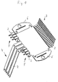
- the semiconductor component 1 shown schematically in FIG. 2 has the same in such integrated components usual cuboid and flat design in which lateral electrical connections in the form of thin wires (not shown) are brought out. These lines are made by bonding, for example by Ultrasonic welding, connected to sheet metal sections 2 by stamping and Cold forming have received the design and arrangement shown in Fig. 1.
- the sheet metal sections 2 are the same Form electrical conductors, arranged in three groups. There is a first group 3 of a total of eighteen sheet metal sections 2 which are angled by approximately 90 ° and extend to one side of the semiconductor device 1. Is opposite a further group 4 of sheet metal sections formed from three sheet metal sections exists, which is also approximately 90 ° from the level of the semiconductor component 1 turned out, but in the opposite direction to that of group 3. These sheet metal sections also have a greater length than the aforementioned ones on.
- the group 5 which the group 4 of sheet metal sections 2 includes, consists of a pair of three sheet metal sections, each are bent twice by 90 °, but in the opposite direction, so that the free ends of the sheet metal sections of group 5 are parallel to the semiconductor component 1 level.
- there are two sheet metal sections 6 is provided, which extends to the other two long sides of the semiconductor component 1 extend and have the purely mechanical function.
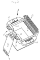
- the groups 3, 4, 5 of sheet metal sections 2 and the two sheet metal sections 6 are positioned in a common casting body 7 and mechanically with one another connected.
- the potting body 7 encloses in the embodiment shown the semiconductor device 1 on all four sides, so that it through the potting body 7 is integrated and protected like a frame.
- the sheet metal sections 6 serve for fastening the entire power part component 8 thus formed Plastic potting body 7 is electrically non-conductive.
- a further potting body 9 is provided, which encloses part of the sheet metal sections of group 4.
- This potting body 9 holds the sheet metal sections embedded therein in their position to each other and at the same time isolates them from the outside in this area.
- the group 4 shows the connecting line to the motor, which is through the frequency converter should be controlled.
- the free ends of the Sheet metal sections 2 of groups 3 and 5 are designed to be tapering so that they form the plug-side part of a plug connection, the socket-side part of Boards is arranged, namely on a schematically shown in Fig. 3, the Control and regulating component forming circuit board 10 and on an intermediate circuit receiving board 11, which may also include parts of the input circuit.
- This intermediate circuit component is connected via group 5 of sheet metal sections 2 and also assigns corresponding recordings for those by the Sheet metal sections 2 of the group 5 formed connector.
- the mechanical fastening of the entire power part component thus formed is expediently carried out via the lateral sheet metal sections 6 such that the Semiconductor component 1 is in direct contact with a heat distributor, by which there dissipate waste heat.
- the semiconductor component 1, which is not described in detail here, comprises at least the power electronics of the power section, in the present exemplary embodiment but also the rectifier of the input circuit.
- the bend the free ends of the sheet metal sections can, like the finished molded form 2 illustrates, also varied after casting by cold working become.
- the sheet metal sections can also be provided depending on the arrangement the other assemblies to deform accordingly before casting.
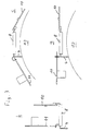
- FIG. 3a that is Power part component essentially in the same plane as the intermediate circuit component 11 and the control and regulating component 10, which on both sides of the Power component 8 are arranged.
- connection to the motor is made perpendicular to it.
- control circuit boards are and control component 10 and the intermediate circuit component 11 perpendicular to the power component 8, d. H. to the plane in which the semiconductor component 1 lies, arranged.
- the frequency converter can be cuboid Housing are arranged.
- 3c shows how the aforementioned three components 8, 10 and 11 can be arranged following the outer circumference of the motor housing 12.
- the line connection is made via group 4 of Sheet metal sections 2 perpendicular downwards to the engine.
- the power component 8 allows with its in a frame-shaped Casting body 7 incorporated sheet metal sections 2 an inexpensive Solution of the electrical and mechanical connection of the individual Assemblies to each other.
Landscapes
- Engineering & Computer Science (AREA)
- Power Engineering (AREA)
- Microelectronics & Electronic Packaging (AREA)
- Inverter Devices (AREA)
Abstract
Description
- Fig. 1
- in vereinfachter perspektivischer Darstellung die Ausbildung und Anordnung der Blecheinschnitte vor dem Herstellen des Vergusskörpers,
- Fig. 2
- in gleicher Darstellung die Anordnung nach dem Herstellen des Vergusskörpers, wobei der Halbleiterbaustein zu Übersichtszwecken außerhalb des Vergusskörpers dargestellt ist und
- Fig. 3
- in schematischer Darstellung drei mögliche Anordnungen der Bauteile eines Frequenzumrichters.
- 1 -
- Halbleiterbauelement
- 2 -
- Blechabschnitte
- 3 -
- Gruppe von Blechabschnitten zum Steuer- und Regelbauteil
- 4 -
- Gruppe von Blechabschnitten zum Motoranschluss
- 5 -
- Gruppe von Blechabschnitten zum Zwischenkreisbauteil
- 6 -
- Blechabschnitte zur Befestigung
- 7 -
- Vergusskörper
- 8 -
- Leistungsteilbauteil
- 9 -
- Vergusskörper der Gruppe 4
- 10 -
- Steuer- und Regelbauteil
- 11 -
- Zwischenkreisbauteil
- 12 -
- Motor
Claims (8)
- Frequenzumrichter für einen Elektromotor im Wesentlichen bestehend aus einem in einem gemeinsamen Halbleiterbaustein (1) integrierten Leistungsteil, einem mindestens die Zwischenkreiselektronik aufnehmenden Bauteil (11) (Zwischenkreisbauteil) und einem die Steuer- und Regelelektronik aufnehmenden Bauteil (10) (Steuer- und Regelbauteil), dadurch gekennzeichnet, dass die elektrischen Verbindungen vom Halbleiterbaustein (1) des Leistungsteils zum Zwischenkreisbauteil (11) und vom Halbleiterbaustein (1) des Leistungsteils zum Steuer- und Regelbauteil (10) durch Blechabschnitte (2) gebildet sind, die durch einen gemeinsamen Vergusskörper (7) positioniert und mechanisch miteinander verbunden sind, wobei das Zwischenkreisbauteil (11) und das Steuer- und Regelbauteil (10) jeweils eine Platine aufweisen und die durch die Blechabschnitte (2) gebildeten Leitungen des Leistungsteils an diese Platinen anschließen.
- Frequenzumrichter nach Anspruch 1, dadurch gekennzeichnet, dass die vom Halbleiterbaustein (1) des Leistungsteils zum Motor führenden Leitungen ebenfalls durch im Vergusskörper (7) gehaltene Blechabschnitte (2) gebildet sind, die am Motor anschließen.
- Frequenzumrichter nach einem der vorhergehenden Ansprüche, dadurch gekennzeichnet, dass der Vergusskörper (7) den Halbleiterbaustein (1) an mindestens drei Seiten umschließt.
- Frequenzumrichter nach einem der vorhergehenden Ansprüche, dadurch gekennzeichnet, dass der Vergusskörper (7) eine Halterung für den Frequenzumrichter bildet.
- Frequenzumrichter nach einem der vorhergehenden Ansprüche, dadurch gekennzeichnet, dass freie Enden von Blechabschnitten (2) Teile von Steckverbindungen zu mindestens einem Anschlussbaustein (10, 11) bilden.
- Frequenzumrichter nach einem der vorhergehenden Ansprüche, dadurch gekennzeichnet, dass die Blechabschnitte (2) durch Stanzen oder Laserschneiden gebildet sind.
- Frequenzumrichter nach einem der vorhergehenden Ansprüche, dadurch gekennzeichnet, dass die zum Zwischenkreisbauteil (11) weisenden Leitungen (5) zu einer Seite des Vergusskörpers (7), die zum Steuer- und Regelbauteil (10) weisenden Leitungen (3) zur gegenüberliegend abgewandten Seite des Vergusskörpers (7) und die zum Motor weisenden Leitungen (4) zu einer dazu jeweils um 90° versetzten Seite herausgeführt sind.
- Frequenzumrichter nach einem der vorhergehenden Ansprüche, dadurch gekennzeichnet, dass die Leitungsanschlüsse des Halbleiterbausteins (1) durch Schweißen mit den Blechabschnitten (2) leitungsverbunden sind.
Applications Claiming Priority (2)
| Application Number | Priority Date | Filing Date | Title |
|---|---|---|---|
| DE10010919 | 2000-03-06 | ||
| DE10010919A DE10010919A1 (de) | 2000-03-06 | 2000-03-06 | Frequenzumrichter |
Publications (2)
| Publication Number | Publication Date |
|---|---|
| EP1133047A1 true EP1133047A1 (de) | 2001-09-12 |
| EP1133047B1 EP1133047B1 (de) | 2007-12-26 |
Family
ID=7633728
Family Applications (1)
| Application Number | Title | Priority Date | Filing Date |
|---|---|---|---|
| EP01105084A Expired - Lifetime EP1133047B1 (de) | 2000-03-06 | 2001-03-02 | Frequenzumrichter |
Country Status (3)
| Country | Link |
|---|---|
| US (1) | US6542378B2 (de) |
| EP (1) | EP1133047B1 (de) |
| DE (2) | DE10010919A1 (de) |
Families Citing this family (9)
| Publication number | Priority date | Publication date | Assignee | Title |
|---|---|---|---|---|
| DE10004059A1 (de) * | 2000-02-01 | 2001-11-08 | Buhler Motor Gmbh | Mehrphasen-Motor |
| US7796162B2 (en) | 2000-10-26 | 2010-09-14 | Front Row Technologies, Llc | Providing multiple synchronized camera views for broadcast from a live venue activity to remote viewers |
| US8583027B2 (en) | 2000-10-26 | 2013-11-12 | Front Row Technologies, Llc | Methods and systems for authorizing computing devices for receipt of venue-based data based on the location of a user |
| US7782363B2 (en) | 2000-06-27 | 2010-08-24 | Front Row Technologies, Llc | Providing multiple video perspectives of activities through a data network to a remote multimedia server for selective display by remote viewing audiences |
| US7149549B1 (en) | 2000-10-26 | 2006-12-12 | Ortiz Luis M | Providing multiple perspectives for a venue activity through an electronic hand held device |
| DE10306227B4 (de) * | 2003-02-13 | 2009-01-02 | Sew-Eurodrive Gmbh & Co. Kg | Leistungsmodul und Umrichter |
| DE102004003798A1 (de) * | 2004-01-26 | 2005-08-18 | Meiko Maschinenbau Gmbh & Co. Kg | Betriebsphasenabhängige Steuerung einer Einrichtung zur Wärmerückgewinnung an Spülmaschinen |
| EP2500577B1 (de) * | 2011-03-12 | 2016-06-22 | Grundfos Management a/s | Heizungsumwälzpumpe |
| DE102011085872B4 (de) * | 2011-11-07 | 2023-03-23 | Lenze Se | Frequenzumrichter und Federelement hierfür |
Citations (5)
| Publication number | Priority date | Publication date | Assignee | Title |
|---|---|---|---|---|
| US4458305A (en) * | 1981-05-12 | 1984-07-03 | Lucas Industries Plc | Multi-phase transistor/diode bridge circuit |
| US5410450A (en) * | 1991-12-10 | 1995-04-25 | Fuji Electric Co., Ltd. | Internal wiring structure of a semiconductor device |
| US5471089A (en) * | 1992-06-30 | 1995-11-28 | Mitsubishi Denki Kabushiki Kaisha | Semiconductor power module |
| US5675223A (en) * | 1995-05-25 | 1997-10-07 | Sanden Corp. | Circuit board unit for driving and controlling motor that drives compressor for air-conditioner |
| US5914577A (en) * | 1996-04-18 | 1999-06-22 | International Rectifier Corporation | Power train partition for 10 horsepower motor controller |
Family Cites Families (10)
| Publication number | Priority date | Publication date | Assignee | Title |
|---|---|---|---|---|
| US4581695A (en) * | 1984-12-12 | 1986-04-08 | Sundstrand Corporation | Rectifier assembly |
| DE3751064T2 (de) * | 1986-12-19 | 1995-06-08 | Fanuc Ltd | Motorantriebseinheit. |
| US5132877A (en) * | 1990-07-05 | 1992-07-21 | Branan Mac W | Molded electrical assembly having an integral connector |
| KR20000052934A (ko) * | 1996-10-31 | 2000-08-25 | 마에다 시게루 | 제어장치 일체형 회전기계 및 인버터장치 |
| DE19649798A1 (de) * | 1996-12-02 | 1998-06-04 | Abb Research Ltd | Leistungshalbleitermodul |
| US5742484A (en) * | 1997-02-18 | 1998-04-21 | Motorola, Inc. | Flexible connector for circuit boards |
| DE19727202A1 (de) * | 1997-06-26 | 1999-01-28 | Grundfos As | Tauchmotoreinheit |
| DE19751109A1 (de) * | 1997-11-18 | 1999-05-20 | Siemens Ag | Kunststoffverbundkörper sowie Verfahren und Werkstoff zum Herstellen eines Kunststoffverbundkörpers |
| US5914860A (en) * | 1998-01-20 | 1999-06-22 | Reliance Electric Industrial Company | Small volume heat sink/electronic assembly |
| US6031730A (en) * | 1998-11-17 | 2000-02-29 | Siemens Automotive Corporation | Connector for electrically connecting circuit boards |
-
2000
- 2000-03-06 DE DE10010919A patent/DE10010919A1/de not_active Withdrawn
-
2001
- 2001-03-02 EP EP01105084A patent/EP1133047B1/de not_active Expired - Lifetime
- 2001-03-02 DE DE50113407T patent/DE50113407D1/de not_active Expired - Lifetime
- 2001-03-05 US US09/799,303 patent/US6542378B2/en not_active Expired - Lifetime
Patent Citations (5)
| Publication number | Priority date | Publication date | Assignee | Title |
|---|---|---|---|---|
| US4458305A (en) * | 1981-05-12 | 1984-07-03 | Lucas Industries Plc | Multi-phase transistor/diode bridge circuit |
| US5410450A (en) * | 1991-12-10 | 1995-04-25 | Fuji Electric Co., Ltd. | Internal wiring structure of a semiconductor device |
| US5471089A (en) * | 1992-06-30 | 1995-11-28 | Mitsubishi Denki Kabushiki Kaisha | Semiconductor power module |
| US5675223A (en) * | 1995-05-25 | 1997-10-07 | Sanden Corp. | Circuit board unit for driving and controlling motor that drives compressor for air-conditioner |
| US5914577A (en) * | 1996-04-18 | 1999-06-22 | International Rectifier Corporation | Power train partition for 10 horsepower motor controller |
Also Published As
| Publication number | Publication date |
|---|---|
| DE10010919A1 (de) | 2001-09-20 |
| US6542378B2 (en) | 2003-04-01 |
| DE50113407D1 (de) | 2008-02-07 |
| EP1133047B1 (de) | 2007-12-26 |
| US20020021051A1 (en) | 2002-02-21 |
Similar Documents
| Publication | Publication Date | Title |
|---|---|---|
| DE102015214457B4 (de) | Ansteuereinheit mit anschlüssen in federndem kontakt miteinander | |
| EP2082472B1 (de) | Elektromotor | |
| EP1171680B1 (de) | Motorgehäuse und poltopf, insbesondere für fensterheber- oder schiebedachmotoren | |
| DE69505086T2 (de) | Zwischenkontakt für elektrischen Anschlusskasten | |
| DE102006034991A1 (de) | Elektrische Servolenkungsvorrichtung | |
| DE3300558A1 (de) | Buerstenkasten-montageuntergruppe fuer einen elektromotor sowie verfahren zum zusammenbauen eines elektromotors | |
| DE102013209315A1 (de) | Steuereinrichtung und mit einer Steuereinrichtung integrierte elektrische Rotationsmaschine | |
| DE2747229A1 (de) | Mehrphasenvollweggleichrichter | |
| EP3340444A2 (de) | Elektromotor und kühlerlüftermodul mit einem solchen elektromotor | |
| EP3477781A1 (de) | Steckerbuchse für leiterplatinen | |
| DE3506763A1 (de) | Elektromotor in flachbauweise | |
| EP1133047B1 (de) | Frequenzumrichter | |
| DE3921889A1 (de) | Endrahmen eines kleinen motors | |
| DE102009035594A1 (de) | Kabelverbinderadapter mit variabler Richtung | |
| EP2410634B1 (de) | Elektrokleinmotor sowie Verfahren zur Herstellung eines Elektrokleinmotors | |
| DE102018214104A1 (de) | Elektromaschine und Montageverfahren | |
| DE202016104464U1 (de) | Leistungsverteilerkasten mit einer Schraube mit einer Hülse | |
| WO2005036700A1 (de) | Schirmanbindung | |
| DE102010012404A1 (de) | Phasenanschlussverbindungen für einen Stator mit Stabwicklungen | |
| EP2270821B1 (de) | Windenergieanlage mit einem Umrichter und wenigstens einem Hochleistungswiderstand | |
| DE112017005289T5 (de) | Elektrische Maschine mit eingepresstem Elektronikmodul | |
| DE20113687U1 (de) | Elektrischer Stellantrieb für ein Kraftfahrzeug | |
| DE69602143T2 (de) | Gehäuse für ein elektrisches Bauteil | |
| EP4068923A1 (de) | Kühlvorrichtung zur kühlung eines halbleitermoduls und umrichter mit der kühlvorrichtung | |
| DE10010961A1 (de) | Motorbaueinheit für ein Tauchpumpenaggregat |
Legal Events
| Date | Code | Title | Description |
|---|---|---|---|
| PUAI | Public reference made under article 153(3) epc to a published international application that has entered the european phase |
Free format text: ORIGINAL CODE: 0009012 |
|
| AK | Designated contracting states |
Kind code of ref document: A1 Designated state(s): DE FR GB IT Kind code of ref document: A1 Designated state(s): AT BE CH CY DE DK ES FI FR GB GR IE IT LI LU MC NL PT SE TR |
|
| AX | Request for extension of the european patent |
Free format text: AL;LT;LV;MK;RO;SI |
|
| 17P | Request for examination filed |
Effective date: 20011219 |
|
| AKX | Designation fees paid |
Free format text: DE FR GB IT |
|
| GRAP | Despatch of communication of intention to grant a patent |
Free format text: ORIGINAL CODE: EPIDOSNIGR1 |
|
| GRAS | Grant fee paid |
Free format text: ORIGINAL CODE: EPIDOSNIGR3 |
|
| GRAA | (expected) grant |
Free format text: ORIGINAL CODE: 0009210 |
|
| AK | Designated contracting states |
Kind code of ref document: B1 Designated state(s): DE FR GB IT |
|
| REG | Reference to a national code |
Ref country code: GB Ref legal event code: FG4D Free format text: NOT ENGLISH |
|
| REF | Corresponds to: |
Ref document number: 50113407 Country of ref document: DE Date of ref document: 20080207 Kind code of ref document: P |
|
| GBT | Gb: translation of ep patent filed (gb section 77(6)(a)/1977) |
Effective date: 20080227 |
|
| ET | Fr: translation filed | ||
| PLBE | No opposition filed within time limit |
Free format text: ORIGINAL CODE: 0009261 |
|
| STAA | Information on the status of an ep patent application or granted ep patent |
Free format text: STATUS: NO OPPOSITION FILED WITHIN TIME LIMIT |
|
| 26N | No opposition filed |
Effective date: 20080929 |
|
| REG | Reference to a national code |
Ref country code: FR Ref legal event code: PLFP Year of fee payment: 16 |
|
| REG | Reference to a national code |
Ref country code: FR Ref legal event code: PLFP Year of fee payment: 17 |
|
| REG | Reference to a national code |
Ref country code: FR Ref legal event code: PLFP Year of fee payment: 18 |
|
| PGFP | Annual fee paid to national office [announced via postgrant information from national office to epo] |
Ref country code: DE Payment date: 20200319 Year of fee payment: 20 Ref country code: IT Payment date: 20200325 Year of fee payment: 20 Ref country code: GB Payment date: 20200325 Year of fee payment: 20 |
|
| PGFP | Annual fee paid to national office [announced via postgrant information from national office to epo] |
Ref country code: FR Payment date: 20200324 Year of fee payment: 20 |
|
| REG | Reference to a national code |
Ref country code: DE Ref legal event code: R071 Ref document number: 50113407 Country of ref document: DE |
|
| REG | Reference to a national code |
Ref country code: GB Ref legal event code: PE20 Expiry date: 20210301 |
|
| PG25 | Lapsed in a contracting state [announced via postgrant information from national office to epo] |
Ref country code: GB Free format text: LAPSE BECAUSE OF EXPIRATION OF PROTECTION Effective date: 20210301 |