EP1133053A2 - Piezoelektrische Resonatoranordnung - Google Patents
Piezoelektrische Resonatoranordnung Download PDFInfo
- Publication number
- EP1133053A2 EP1133053A2 EP01890064A EP01890064A EP1133053A2 EP 1133053 A2 EP1133053 A2 EP 1133053A2 EP 01890064 A EP01890064 A EP 01890064A EP 01890064 A EP01890064 A EP 01890064A EP 1133053 A2 EP1133053 A2 EP 1133053A2
- Authority
- EP
- European Patent Office
- Prior art keywords
- resonator
- arrangement according
- elements
- holding
- arrangement
- Prior art date
- Legal status (The legal status is an assumption and is not a legal conclusion. Google has not performed a legal analysis and makes no representation as to the accuracy of the status listed.)
- Granted
Links
Images

Classifications
-
- H—ELECTRICITY
- H03—ELECTRONIC CIRCUITRY
- H03H—IMPEDANCE NETWORKS, e.g. RESONANT CIRCUITS; RESONATORS
- H03H9/00—Networks comprising electromechanical or electro-acoustic elements; Electromechanical resonators
- H03H9/02—Details
- H03H9/05—Holders or supports
- H03H9/09—Elastic or damping supports
Definitions
- the invention relates to a piezoelectric resonator arrangement
- a piezoelectric resonator arrangement comprising a holder with at least two mounting elements and at least one platelet-shaped piezoelectric Resonator with at least one excitation electrode, at least one of which is electrical conductive strip preferably extends radially towards the edge of the resonator, the resonator being clamped between the support elements, of which at least one force is applied to the resonator, and the immediate and lie directly on the or one of the outer surfaces of the resonator.
- the resonance frequency of a piezoelectric resonator is next to the effective ones Material constants and the physical dimensions largely depend on the interaction with its environment (e.g. pressure, temperature, mass load). Out of it there are naturally two fundamentally different areas of application.
- piezoelectric resonators are used as the frequency standard, whereby the resonator is usually located in the feedback branch of an oscillator and thereby the oscillator frequency stabilized near resonance frequency.
- the influences of the environment on the resonance frequency through hermetically sealed housings, which are either filled with protective gas or evacuated are kept as constant as possible.
- To the Others use piezoelectric resonators as the sensor element measured changes in the resonance properties to the physical or chemical Properties or their temporal change in the environment can be drawn. In Both applications require mounting and contacting the resonator.
- the resonator In the case of frequency standards, the resonator is usually in standardized housings mounted, the electrodes are glued to the leads and therefore conductive the resonator is not interchangeable.
- the resonator In the case of microbalance sensor application. QCM-Quartz Crystal Microbalance), the resonator (Dickerscherschwinger) in accordingly constructed brackets which are usually dismantled installed.
- the resonator is by resilient contact elements, which axially acting on the resonator holding forces exert and thus also against the holding part lying at ground potential presses, contacts on both sides and held stable in position (e.g. microbalance sensor holder of Leybold Inficon).
- this "axial" contacting or mounting occurs in addition to different thermal expansions between the resonator surface and the bracket also for changes in the contact forces of the spring elements and thus to undefined Contact resistance.
- both temperature-compensated cuts are used (e.g. quartz AT cut), as well as cooling the holder during the measurement or thermostated.
- Axial contacting is also used to hold the piezoelectric resonator according to DE 34 27 646 A, in which the resonator with one of its flat top surfaces the resonator holder rests on flags and is fixed to it by gluing.
- the bracket affects the vibration characteristics of the resonator according to JP 57-92913 A.
- a disk-shaped resonator plate is passed through Axial support and gluing with the mounting elements positioned and fixed on which mounting elements also positioning aids in the form of to the Shell surfaces of the resonator adjacent elements are present.
- a holding structure is described for flat shear vibrators in EP 0 626 212 B1, in which the mounting elements abut the top surfaces of a flat resonator and clamp it by elastic, axially acting pressure forces as well as those on the cover surfaces electrically contact the arranged electrodes.
- this arrangement is due to the completely different vibration node levels in no case applicable.
- This type of holder also leads to those applications difficulties or disabilities where the electrodes are freely accessible or other structures on the top surface (s) of the resonator is essential, for example in microbalances in which particles are deposited on the cover surfaces should and often also coatings are applied to the deposition of the particles to be determined.
- the object of the invention is a simple arrangement for mechanical mounting propose including the electrical contacting of a piezoelectric resonator, in which for resonators of all fields of application, in particular for microbalance and / or sensor applications, the vibration and resonance properties as unaffected as possible stay from the bracket and contact.
- This advantage is also said to be in a wide temperature range, so that the temperature-related hysteresis to minimize the resonance properties.
- this object is achieved in that the resonator is bonded between the mounting elements, the electrically conductive Stripe extends at least to the outer surface of the resonator, and at least one non-adhesive electrical contact point with the resonator on the or one of the lateral surfaces of the resonator is provided, the electrical contacting forces essentially lie in one plane with the resonator.
- the insertion of the resonator is therefore essential Simplified, since no additional gluing must be provided between form an intermediate layer between the mounting elements and the resonator material. The holding and contacting forces are already provided by the mounting elements themselves.
- those of the Holding elements exerted electrical contacting forces essentially radially to Center of the resonator directed.
- At least one the mounting elements are provided and at least one electrical contact surface facing one of the outer surfaces of the resonator.
- At least two mounting elements each have at least one electrical contact surface
- This electrically conductive connection of the contact surfaces can be electrical on the mounting elements via the excitation electrode on the resonator Sizes can be determined or specified directly, but also others, with these electrical parameters related parameters.
- the electrical resistance between the contact points on the resonator be determined when the electrical contact surfaces of two mounting elements connected to one another via at least one arrangement for measuring the electrical resistance are.
- the resistance can then be used as a measure of the temperature in question Excitation electrode or the resonator can be used.
- Such an arrangement are those parts of the mounting arrangement which are responsible for the amount of Holding forces are responsible, located outside the area in which Preferential temperature changes occur.
- the holding and contacting forces can also here kept essentially constant over the entire application temperature range and the tolerances are compensated. For example, in the case of sensor arrangements the operation of heating the volume around the resonator or resonator even the elastic part of it is removed, so that the heating only to a small extent Part or not at all on the mechanical and elastic properties of the elastic deformable part of the bracket assembly can impact.
- the resonance frequency of a piezoelectric resonator in the invention Bracket arrangement only slightly influenced by the bracket and also the hysteresis the resonance frequency is reduced in a temperature range from room temperature to approx. 700 ° C.
- At least one of the mounting elements as an elongated holding arm with at least one essentially rigid longitudinal section and a substantially elastically deformable portion, which one good holding effect and dimensional stability, especially when arranging the rigid section with the resonator, and the resonator is simply inserted and exchanged can, since at least a substantial portion of the support arm is moved to the side for this purpose can be.
- the holding elements are provided with holding structures, which specify a defined orientation of the resonator used can be the advantageous one Alignment of the resonator with respect to the mounting elements and the ones they exert Forces are guaranteed safely and handling, especially the insertion of the Resonators in the arrangement is significantly simplified.
- At least the mounting elements are preferred are made in one piece from a ceramic material. This choice of materials combines simple Manufacture with the best mechanical and thermal properties.
- Bracket assembly that is stable for most application temperature ranges to obtain the necessary electrical lines and contact surfaces on the Bracket assembly made from direct coatings of conductive materials.
- Preferably sputtered metal coatings are provided. So that is the temperature resistance of the line structures up to approx. 800 ° C.
- the resonator is a thickness shear or thickness expansion transducer is. Due to the location of the node planes of these special resonators, force is applied for holding and contacting in the plane of the resonator plate, preferably even the radial force alignment, the least possible influence on the vibration parameters guaranteed by the necessary forces.
- the resonator is advantageously provided with at least one coating, in particular one allowing or improving the deposition of particles on the resonator surface Coating.
- FIG. 1 shows the forces on a resonator plate according to the state of the Technique
- Fig. 2 is a top view of a circular resonator plate according to the invention with electrodes and a conductive portion extending to the edge thereof
- Fig. 3 is a 1 on the plate of FIG. 2 with an essentially radial holder
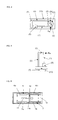
- Fig. 4 is an arrangement with holding arms, which are aligned parallel to the resonator plate
- 5 is an arrangement with holding arms perpendicular to the resonator plate
- FIG. 6 shows a plan view of a flat ceramic plate as a mounting arrangement.
- the preferred shape is for piezoelectric ones Resonators, especially for microbalance sensor applications and as frequency standards, the flat, substantially disc-shaped design shown in the drawing figures.
- the circular Resonator plate 1 electrodes 2 applied.
- These electrodes 2 can, in microbalance arrangements be provided as a collecting and counter electrode. Of course it could there may also be only one electrode on one side of the resonator plate 1. Even additional ones Coatings to improve the deposition of particles on the resonator plate 1 are possible on or around the electrodes 2.
- the or at least one Electrode 2 is applied close to the edge of resonator 1. With such an arrangement As in FIG. 1, the holding or contact forces FR act according to the prior art Edge of the resonators in the axial direction is normal to the node level of the piezoelectric excitable main vibration (thickness shear or thickness expansion vibration).
- the resonator plate 1 carried at its edge by mounting elements is that which acts radially on the resonator plate at at least two clamping points 3 Generate forces FR.
- the force vectors FR lie in the node plane of the piezoelectric excitable main vibration (thickness shear or thickness expansion vibration).
- the electrodes 2 which are only a part of the flat ones Cover the surface (s) of the plate 1 with conductive strips, so-called contact tabs 2a. These preferably extend radially oriented to the outer surface of the Resonator plate 1.
- the resonator 1 is at its Edge held by radial forces FR and the electrical contact is simultaneously made by contact surfaces on the support elements, which are connected to the ends of the radial Contact tabs 2a come into contact on the outer surface.
- the force vectors of the holding forces are preferably in the arrangement according to the invention in the node plane of the piezoelectrically excitable main vibration of the resonator, which has a corresponding crystallographic orientation. This applies to both thick shear as well as for thickness expansion vibrations.
- Fig. 3 is a resonator 1 with bilateral phase at the edge and a similar electrode geometry as shown in Figure 2, but the contact lugs 2a extend to the node level the main vibration to be excited piezoelectrically (thickness shear or thickness expansion vibration).
- the holding and contacting forces occur at the phase (F), the resulting holding or contact forces (FR) again parallel to the node level of the main vibration to be excited piezoelectrically, i.e. radially on the resonator plate 1 act.
- the peripheral region of the resonator plate 1 is not flat, but in an edge tapered so that in cooperation with corresponding structures in the mounting elements are given a precisely defined orientation of the resonator 1 and can be kept safely. Also easier when inserting and replacing the resonator plate 1 such a design the handling and lengthy adjustments are unnecessary.
- Fig. 4 shows a possible arrangement in which the resonator plate 1 in the through two opposite elongated support arms 6, 7 defined level.
- the holding arm 6 is essentially rigid and preferably also fixed to the base plate 10 of the Base structure of the bracket assembly connected, while also substantially rigid Holding arm 7 via an elastic element 8 or an elastically deformable longitudinal section is connected to the basic structure and thus the largely temperature-independent holding or contacting forces FR exerts on the resonator plate 1.
- the electrical contact is produced via the connection 9 and the holding arms 6, 7 on the electrodes 2 of the resonator.
- Fig. 5 shows another example of a possible arrangement in which the resonator plate 1 is normal to the level defined by the two holding arms 6, 7. Also in this arrangement, the holding or contacting forces FR through the holding arm 7, which is connected to the base plate 10 via the elastic element 8, and generates the electrical one Contact via the connection 9 and the holding arms 6, 7 on the electrodes of the resonator plate 1 manufactured.
- the holding arm 6 is firmly connected to the base plate 10.
- FIG. 6 Another embodiment of a mounting arrangement according to the invention shows the Fig. 6, in which a plan view of a ceramic holder arrangement is shown.
- the Holding arms 6, 7 consist of two longitudinal sections, of which that longitudinal section 6a, 7a, which comes into contact with the resonator plate 1 and also in the area of greatest warming lies, with a larger cross section and is therefore essentially rigid.
- the Warming can also be desirable and particularly intensive, especially with sensor and microbalance arrangements.
- the longitudinal sections 6b closer to the base structure 10, 7b are designed with a smaller cross-section, and are therefore elastically deformable for Exercise of the holding and possibly also contacting forces to the electrode 2 on the resonator plate 1 responsible. Because they are outside the range of heating the resonator plate 1 and, moreover, quickly transfer the heat introduced to the base structure 10 their mechanical and elastic properties are dependent on temperature changes hardly influenced at all in the area of the resonator plate 1.
- bracket arm 11 which is also elastic on the base structure 10 is attached.
- Elongated hole 12 is provided, which is an elastic axial displacement of the third Bracket 11 allowed.
- resonator plates 1 can also be used, of whose electrode 2 at least two essentially radial contact lugs 2a to the lateral surface of the resonator 1 run. It is then possible if at least two mounting elements 6, 7, 11 at least one electrical contact surface is provided via this electrically conductive connection electrical sizes of the electrode 2, but also other, with these electrical sizes related parameters of the resonator 1 itself, to determine directly or to specify. For example, the electrical resistance between the contact points be determined on the resonator when the electrical contact surfaces of two mounting elements via at least one arrangement for measuring the electrical resistance with one another are connected, and as a measure of the respective temperature of the relevant excitation electrode or the resonator can be used. Conversely, it is also possible via an appropriately designed circuit, the resonator through direct current flow to be heated or thermostated by at least one electrode.
- the optimal orientation and positioning of the electrically conductive contact tabs 2a can be calculated using the Ratajski coefficient. This method allows the Lay contact flags 2a in such a way that the influence of the contacting forces on the vibration properties of the resonator 1, preferably the resonance properties, is minimized is caused by the mechanical stresses in the resonator due to the attack of the support arms be reduced as much as possible (M. Mizan & A. Ballato, "The Stress Coefficient of Frequency of Quartz Plate Resonators ", Proc. 37th AFCS, p 194-199, 1983).
- the necessary electrical cables are, as on all mounting arrangements possible, preferably by sputtered coatings made of conductive metal, preferably Platinum or gold.
Landscapes
- Physics & Mathematics (AREA)
- Acoustics & Sound (AREA)
- Piezo-Electric Or Mechanical Vibrators, Or Delay Or Filter Circuits (AREA)
Abstract
Description
Claims (15)
- Piezoelektrische Resonatoranordnung, umfassend eine Halterung mit zumindest zwei Halterungselementen und zumindest einem plättchenförmigen piezoelektrischen Resonator mit mindestens einer Anregungselektrode, von der zumindest ein elektrisch leitender Streifen vorzugsweise radial in Richtung des Randes des Resonators hin ausgeht, wobei der Resonator zwischen den Halterungselementen eingespannt ist, von welchen zumindest eines auf den Resonator hin mit einer Kraft beaufschlagt ist, und die unmittelbar und direkt an der bzw. einer der Mantelflächen des Resonators anliegen, dadurch gekennzeichnet, daß der Resonator (1) verklebungsfrei zwischen den Halterungselementen (6, 7, 11) fixiert ist, sich der elektrisch leitende Streifen zumindest bis auf die Mantelfläche des Resonators erstreckt, und mindestens eine verklebungsfreie elektrische Kontaktstelle mit dem Resonator (1) an der bzw. einer der Mantelflächen des Resonators (1) vorgesehen ist, wobei die elektrischen Kontaktierungskräfte im wesentlichen mit dem Resonator (1) in einer Ebene liegen.
- Anordnung nach Anspruch 1, dadurch gekennzeichnet, dass die von den Halterungselementen (6, 7, 11) ausgeübten elektrischen Kontaktierungskräfte im wesentlichen radial zum Zentrum des Resonators (1) gerichtet sind.
- Anordnung nach Anspruch 1 oder 2, dadurch gekennzeichnet, daß an zumindest einem der Halterungselemente (6, 7, 11) zumindest eine elektrische Kontaktfläche vorgesehen und zumindest einer der Mantelflächen des Resonators (1) zugewandt ist.
- Anordnung nach Anspruch 3, dadurch gekennzeichnet, daß an zumindest zwei Halterungselementen (6, 7, 11) zumindest je eine elektrische Kontaktfläche vorgesehen und zumindest einer der Mantelflächen des Resonators (1) zugewandt ist, dass von mindestens einer Anregungselektrode (2) des Resonators (1) mindestens ein zweiter elektrisch leitfähiger Streifen vorzugsweise radial ausgeht und beide leitfähigen Streifen (2a) sich bis auf die Mantelfläche des Resonators (1) und in den Bereich jeweils einer der elektrischen Kontaktflächen der Halterungselemente (6, 7, 11) erstrecken.
- Anordnung nach Anspruch 4, dadurch gekennzeichnet, daß die elektrischen Kontaktflächen von zwei Halterungselementen (6, 7, 11) über zumindest eine Anordnung zur Messung des elektrischen Widerstandes miteinander verbunden sind.
- Anordnung nach Anspruch 4, dadurch gekennzeichnet, daß die elektrischen Kontaktflächen von zwei Halterungselementen (6, 7, 11) über zumindest eine Anordnung zur Erzeugung und Regelung eines Stromflusses miteinander verbunden sind.
- Anordnung nach einem der Ansprüche 1 bis 6, dadurch gekennzeichnet, dass zumindest eines der Halterungselemente (6, 7, 11) elastisch federnd gelagert bzw. mit der Basisstruktur (10) elastisch federnd verbunden ist.
- Anordnung nach einem der Ansprüche 1 bis 7, dadurch gekennzeichnet, dass die Halterungselemente (6, 7, 11) aus einem im wesentlichen starren (6, 6a, 7, 7a, 11) und einem im wesentlichen elastisch verformbaren Teil (6b, 7b, 11a, 8) besteht, wobei der elastische Teil näher der Basisstruktur (10) liegt.
- Anordnung nach Anspruch 8, dadurch gekennzeichnet, dass zumindest eines der Halterungselemente als länglicher Haltearm (6, 7, 11) mit zumindest einem im wesentlichen starren Längsabschnitt (6a, 7a, 11) und einem im wesentlichen elastisch verformbaren Abschnitt (6b, 7b, 11a) ausgeführt ist.
- Anordnung nach einem der Ansprüche 8 oder 9, dadurch gekennzeichnet, dass zumindest ein im wesentlichen starres Halterungselement (6, 7, 11) durch ein elastisches Element (8) federnd gelagert ist.
- Anordnung nach einem der vorhergehenden Ansprüche, dadurch gekennzeichnet, dass die Halterungselemente (6, 7, 11) mit Haltestrukturen versehen sind, die eine definierte Orientierung des eingesetzten Resonators (1) vorgeben und an welchen die elektrischen Kontaktflächen vorgesehen sind.
- Anordnung nach einem der vorhergehenden Ansprüche, dadurch gekennzeichnet, dass zumindest die Halterungselemente (6, 7, 11), vorzugsweise auch die Basisstruktur (10), vorzugsweise einstückig aus Keramikmaterial angefertigt ist.
- Anordnung nach einem der vorhergehenden Ansprüche, dadurch gekennzeichnet, dass elektrische Leitungen und Kontaktflächen auf der Halterungsanordnung aus direkten Beschichtungen aus elektrisch leitfähigen Materialien vorgesehen sind.
- Anordnung nach zumindest einem der vorhergehenden Ansprüche, dadurch gekennzeichnet, daß der Resonator (1) ein Dickenscher- oder Dickendehnschwinger ist.
- Anordnung nach einem der vorhergehenden Ansprüche, dadurch gekennzeichnet, daß der Resonator (1) mit zumindest einer Beschichtung, insbesonders einer die Abscheidung von Partikeln auf der Resonatoroberfläche erlaubenden bzw. verbessernden Beschichtung, versehen ist.
Applications Claiming Priority (2)
| Application Number | Priority Date | Filing Date | Title |
|---|---|---|---|
| AT0038500A AT410736B (de) | 2000-03-08 | 2000-03-08 | Piezoelektrische resonatoranordnung |
| AT3852000 | 2000-03-08 |
Publications (3)
| Publication Number | Publication Date |
|---|---|
| EP1133053A2 true EP1133053A2 (de) | 2001-09-12 |
| EP1133053A3 EP1133053A3 (de) | 2008-08-27 |
| EP1133053B1 EP1133053B1 (de) | 2009-11-25 |
Family
ID=3673218
Family Applications (1)
| Application Number | Title | Priority Date | Filing Date |
|---|---|---|---|
| EP01890064A Expired - Lifetime EP1133053B1 (de) | 2000-03-08 | 2001-03-07 | Piezoelektrische Resonatoranordnung |
Country Status (4)
| Country | Link |
|---|---|
| US (1) | US20010033123A1 (de) |
| EP (1) | EP1133053B1 (de) |
| AT (2) | AT410736B (de) |
| DE (1) | DE50115233D1 (de) |
Families Citing this family (3)
| Publication number | Priority date | Publication date | Assignee | Title |
|---|---|---|---|---|
| US6984925B2 (en) * | 2002-05-28 | 2006-01-10 | Delaware Capital Formation, Inc | Low acceleration sensitivity mounting structures for crystal resonators |
| US7802466B2 (en) * | 2007-11-28 | 2010-09-28 | Sierra Sensors Gmbh | Oscillating sensor and fluid sample analysis using an oscillating sensor |
| DE102015112044A1 (de) * | 2015-07-23 | 2017-01-26 | Epcos Ag | Halterung für ein piezoelektrisches Bauelement |
Family Cites Families (5)
| Publication number | Priority date | Publication date | Assignee | Title |
|---|---|---|---|---|
| JPS5792913A (en) * | 1980-11-28 | 1982-06-09 | Matsushita Electric Ind Co Ltd | Quartz oscillator |
| DE8120939U1 (de) * | 1981-07-16 | 1981-11-26 | SIEMENS AG AAAAA, 1000 Berlin und 8000 München | Halte- und anschlussvorrichtung fuer einen scheibenfoermigen piezoelektrischen resonator |
| GB2146839B (en) * | 1983-07-27 | 1987-04-01 | Nihon Dempa Kogyo Co | Piezoelectric resonator |
| US4642511A (en) * | 1986-03-31 | 1987-02-10 | Motorola, Inc. | Edge-mounting configuration for at-strip resonators |
| US5250871A (en) * | 1991-06-13 | 1993-10-05 | Westinghouse Electric Corp. | Low vibration sensitivity crystal resonator arrangement |
-
2000
- 2000-03-08 AT AT0038500A patent/AT410736B/de not_active IP Right Cessation
-
2001
- 2001-03-07 DE DE50115233T patent/DE50115233D1/de not_active Expired - Lifetime
- 2001-03-07 EP EP01890064A patent/EP1133053B1/de not_active Expired - Lifetime
- 2001-03-07 AT AT01890064T patent/ATE450080T1/de not_active IP Right Cessation
- 2001-03-08 US US09/802,000 patent/US20010033123A1/en not_active Abandoned
Also Published As
| Publication number | Publication date |
|---|---|
| ATA3852000A (de) | 2002-11-15 |
| EP1133053A3 (de) | 2008-08-27 |
| US20010033123A1 (en) | 2001-10-25 |
| ATE450080T1 (de) | 2009-12-15 |
| DE50115233D1 (de) | 2010-01-07 |
| AT410736B (de) | 2003-07-25 |
| EP1133053B1 (de) | 2009-11-25 |
Similar Documents
| Publication | Publication Date | Title |
|---|---|---|
| DE69321083T2 (de) | Akustische Oberflächenwellenanordnung mit Interdigitalwandler auf einem Substrat-Träger und Verfahren zur Herstellung | |
| AT503816B1 (de) | Piezoelektrischer sensor | |
| DE2700342C3 (de) | Piezoelektrischer Meßwandler | |
| DE2906407C2 (de) | Piezoelektrisches Wandlerelement zum Einbau in Druck-, Kraft- oder Beschleunigungsaufnehmer | |
| EP0407397B1 (de) | Druckgeber zur druckerfassung im brennraum von brennkraftmaschinen | |
| DE1228448B (de) | Beschleunigungsmessgeraet mit Temperaturkompensation | |
| EP1277243B1 (de) | Piezokeramischer mehrschichtbauteil für messgeräte sowie dessen herstellungsverfahren | |
| EP0379839B1 (de) | Stimmgabel-Quarz-Manometer | |
| DE69302258T2 (de) | Piezoelektrischer Transformator mit verbesserter Elektrodenanordnung | |
| DE1797167A1 (de) | U-foermiger mechanischer Vibrator | |
| DE3709720A1 (de) | Kraftsensor, insbesondere zur beschleunigungsmessung | |
| EP0734532A1 (de) | Drehratensensor | |
| DE69410749T2 (de) | Verbesserter Beschleunigungsmessaufnehmer sowie Verfahren zu dessen Herstellung | |
| DE69605680T2 (de) | Monolithischer beschleunigungsmessaufnehmer | |
| DE3427646A1 (de) | Piezoelektrischer resonator | |
| EP1133053B1 (de) | Piezoelektrische Resonatoranordnung | |
| WO1997021986A1 (de) | Mikrosensoren mit siliziummembranen und verfahren zur herstellung derselben | |
| EP0147614B1 (de) | Druckaufnehmer mit Sensorquarz | |
| DE69523655T2 (de) | Beschleunigungsmessaufnehmer und Verfahren zu seiner Herstellung | |
| EP0679874B1 (de) | Schallsensor | |
| EP1745272A1 (de) | Sensor | |
| DE3018285C2 (de) | ||
| EP1651944A1 (de) | Viskosit tssensoranordnung | |
| WO2025011941A1 (de) | Vibrationssensor | |
| EP1393439A1 (de) | Piezoelektrisches resonatorelement der kristallographischen punktgruppe 32 |
Legal Events
| Date | Code | Title | Description |
|---|---|---|---|
| PUAI | Public reference made under article 153(3) epc to a published international application that has entered the european phase |
Free format text: ORIGINAL CODE: 0009012 |
|
| AK | Designated contracting states |
Kind code of ref document: A2 Designated state(s): AT BE CH CY DE DK ES FI FR GB GR IE IT LI LU MC NL PT SE TR |
|
| AX | Request for extension of the european patent |
Free format text: AL;LT;LV;MK;RO;SI |
|
| PUAL | Search report despatched |
Free format text: ORIGINAL CODE: 0009013 |
|
| AK | Designated contracting states |
Kind code of ref document: A3 Designated state(s): AT BE CH CY DE DK ES FI FR GB GR IE IT LI LU MC NL PT SE TR |
|
| AX | Request for extension of the european patent |
Extension state: AL LT LV MK RO SI |
|
| 17P | Request for examination filed |
Effective date: 20090127 |
|
| AKX | Designation fees paid |
Designated state(s): AT BE CH CY DE DK ES FI FR GB GR IE IT LI LU MC NL PT SE TR |
|
| GRAP | Despatch of communication of intention to grant a patent |
Free format text: ORIGINAL CODE: EPIDOSNIGR1 |
|
| GRAS | Grant fee paid |
Free format text: ORIGINAL CODE: EPIDOSNIGR3 |
|
| GRAA | (expected) grant |
Free format text: ORIGINAL CODE: 0009210 |
|
| AK | Designated contracting states |
Kind code of ref document: B1 Designated state(s): AT BE CH CY DE DK ES FI FR GB GR IE IT LI LU MC NL PT SE TR |
|
| REG | Reference to a national code |
Ref country code: GB Ref legal event code: FG4D Free format text: NOT ENGLISH |
|
| REG | Reference to a national code |
Ref country code: CH Ref legal event code: EP |
|
| REG | Reference to a national code |
Ref country code: IE Ref legal event code: FG4D |
|
| REG | Reference to a national code |
Ref country code: CH Ref legal event code: NV Representative=s name: ISLER & PEDRAZZINI AG |
|
| REF | Corresponds to: |
Ref document number: 50115233 Country of ref document: DE Date of ref document: 20100107 Kind code of ref document: P |
|
| REG | Reference to a national code |
Ref country code: NL Ref legal event code: VDEP Effective date: 20091125 |
|
| PG25 | Lapsed in a contracting state [announced via postgrant information from national office to epo] |
Ref country code: PT Free format text: LAPSE BECAUSE OF FAILURE TO SUBMIT A TRANSLATION OF THE DESCRIPTION OR TO PAY THE FEE WITHIN THE PRESCRIBED TIME-LIMIT Effective date: 20100325 Ref country code: SE Free format text: LAPSE BECAUSE OF FAILURE TO SUBMIT A TRANSLATION OF THE DESCRIPTION OR TO PAY THE FEE WITHIN THE PRESCRIBED TIME-LIMIT Effective date: 20091125 |
|
| PG25 | Lapsed in a contracting state [announced via postgrant information from national office to epo] |
Ref country code: CY Free format text: LAPSE BECAUSE OF FAILURE TO SUBMIT A TRANSLATION OF THE DESCRIPTION OR TO PAY THE FEE WITHIN THE PRESCRIBED TIME-LIMIT Effective date: 20091125 |
|
| REG | Reference to a national code |
Ref country code: IE Ref legal event code: FD4D |
|
| PG25 | Lapsed in a contracting state [announced via postgrant information from national office to epo] |
Ref country code: ES Free format text: LAPSE BECAUSE OF FAILURE TO SUBMIT A TRANSLATION OF THE DESCRIPTION OR TO PAY THE FEE WITHIN THE PRESCRIBED TIME-LIMIT Effective date: 20100308 Ref country code: DK Free format text: LAPSE BECAUSE OF FAILURE TO SUBMIT A TRANSLATION OF THE DESCRIPTION OR TO PAY THE FEE WITHIN THE PRESCRIBED TIME-LIMIT Effective date: 20091125 Ref country code: NL Free format text: LAPSE BECAUSE OF FAILURE TO SUBMIT A TRANSLATION OF THE DESCRIPTION OR TO PAY THE FEE WITHIN THE PRESCRIBED TIME-LIMIT Effective date: 20091125 Ref country code: IE Free format text: LAPSE BECAUSE OF FAILURE TO SUBMIT A TRANSLATION OF THE DESCRIPTION OR TO PAY THE FEE WITHIN THE PRESCRIBED TIME-LIMIT Effective date: 20091125 |
|
| BERE | Be: lapsed |
Owner name: AVL LIST GMBH Effective date: 20100331 |
|
| PLBE | No opposition filed within time limit |
Free format text: ORIGINAL CODE: 0009261 |
|
| STAA | Information on the status of an ep patent application or granted ep patent |
Free format text: STATUS: NO OPPOSITION FILED WITHIN TIME LIMIT |
|
| PG25 | Lapsed in a contracting state [announced via postgrant information from national office to epo] |
Ref country code: MC Free format text: LAPSE BECAUSE OF NON-PAYMENT OF DUE FEES Effective date: 20100331 Ref country code: GR Free format text: LAPSE BECAUSE OF FAILURE TO SUBMIT A TRANSLATION OF THE DESCRIPTION OR TO PAY THE FEE WITHIN THE PRESCRIBED TIME-LIMIT Effective date: 20100226 |
|
| 26N | No opposition filed |
Effective date: 20100826 |
|
| REG | Reference to a national code |
Ref country code: FR Ref legal event code: ST Effective date: 20101130 |
|
| PG25 | Lapsed in a contracting state [announced via postgrant information from national office to epo] |
Ref country code: FR Free format text: LAPSE BECAUSE OF NON-PAYMENT OF DUE FEES Effective date: 20100331 |
|
| PG25 | Lapsed in a contracting state [announced via postgrant information from national office to epo] |
Ref country code: BE Free format text: LAPSE BECAUSE OF NON-PAYMENT OF DUE FEES Effective date: 20100331 |
|
| PG25 | Lapsed in a contracting state [announced via postgrant information from national office to epo] |
Ref country code: IT Free format text: LAPSE BECAUSE OF FAILURE TO SUBMIT A TRANSLATION OF THE DESCRIPTION OR TO PAY THE FEE WITHIN THE PRESCRIBED TIME-LIMIT Effective date: 20091125 |
|
| PG25 | Lapsed in a contracting state [announced via postgrant information from national office to epo] |
Ref country code: AT Free format text: LAPSE BECAUSE OF NON-PAYMENT OF DUE FEES Effective date: 20100307 |
|
| PGFP | Annual fee paid to national office [announced via postgrant information from national office to epo] |
Ref country code: CH Payment date: 20120326 Year of fee payment: 12 |
|
| PGFP | Annual fee paid to national office [announced via postgrant information from national office to epo] |
Ref country code: GB Payment date: 20120322 Year of fee payment: 12 Ref country code: FI Payment date: 20120313 Year of fee payment: 12 |
|
| PGFP | Annual fee paid to national office [announced via postgrant information from national office to epo] |
Ref country code: DE Payment date: 20120321 Year of fee payment: 12 |
|
| PG25 | Lapsed in a contracting state [announced via postgrant information from national office to epo] |
Ref country code: LU Free format text: LAPSE BECAUSE OF NON-PAYMENT OF DUE FEES Effective date: 20100307 |
|
| PG25 | Lapsed in a contracting state [announced via postgrant information from national office to epo] |
Ref country code: TR Free format text: LAPSE BECAUSE OF FAILURE TO SUBMIT A TRANSLATION OF THE DESCRIPTION OR TO PAY THE FEE WITHIN THE PRESCRIBED TIME-LIMIT Effective date: 20091125 |
|
| PG25 | Lapsed in a contracting state [announced via postgrant information from national office to epo] |
Ref country code: FI Free format text: LAPSE BECAUSE OF NON-PAYMENT OF DUE FEES Effective date: 20130307 |
|
| REG | Reference to a national code |
Ref country code: CH Ref legal event code: PL |
|
| GBPC | Gb: european patent ceased through non-payment of renewal fee |
Effective date: 20130307 |
|
| REG | Reference to a national code |
Ref country code: DE Ref legal event code: R119 Ref document number: 50115233 Country of ref document: DE Effective date: 20131001 |
|
| PG25 | Lapsed in a contracting state [announced via postgrant information from national office to epo] |
Ref country code: CH Free format text: LAPSE BECAUSE OF NON-PAYMENT OF DUE FEES Effective date: 20130331 Ref country code: LI Free format text: LAPSE BECAUSE OF NON-PAYMENT OF DUE FEES Effective date: 20130331 Ref country code: GB Free format text: LAPSE BECAUSE OF NON-PAYMENT OF DUE FEES Effective date: 20130307 Ref country code: DE Free format text: LAPSE BECAUSE OF NON-PAYMENT OF DUE FEES Effective date: 20131001 |