EP1133071B1 - Raum-Zeit-Sendediversität für TDD/WCDMA Systeme - Google Patents
Raum-Zeit-Sendediversität für TDD/WCDMA Systeme Download PDFInfo
- Publication number
- EP1133071B1 EP1133071B1 EP20000200670 EP00200670A EP1133071B1 EP 1133071 B1 EP1133071 B1 EP 1133071B1 EP 20000200670 EP20000200670 EP 20000200670 EP 00200670 A EP00200670 A EP 00200670A EP 1133071 B1 EP1133071 B1 EP 1133071B1
- Authority
- EP
- European Patent Office
- Prior art keywords
- circuit
- sttd
- data symbol
- symbols
- symbol
- Prior art date
- Legal status (The legal status is an assumption and is not a legal conclusion. Google has not performed a legal analysis and makes no representation as to the accuracy of the status listed.)
- Expired - Lifetime
Links
- 230000004044 response Effects 0.000 claims description 5
- 238000010586 diagram Methods 0.000 description 36
- 239000011159 matrix material Substances 0.000 description 23
- 238000004891 communication Methods 0.000 description 17
- 108010003272 Hyaluronate lyase Proteins 0.000 description 13
- 230000005540 biological transmission Effects 0.000 description 11
- 238000005562 fading Methods 0.000 description 9
- 238000000034 method Methods 0.000 description 5
- 230000000737 periodic effect Effects 0.000 description 5
- 238000004088 simulation Methods 0.000 description 5
- 238000000354 decomposition reaction Methods 0.000 description 4
- 238000001514 detection method Methods 0.000 description 4
- 230000006870 function Effects 0.000 description 4
- 230000000996 additive effect Effects 0.000 description 3
- 239000002131 composite material Substances 0.000 description 3
- 238000013461 design Methods 0.000 description 3
- 238000009472 formulation Methods 0.000 description 3
- 239000000203 mixture Substances 0.000 description 3
- 238000005070 sampling Methods 0.000 description 3
- 230000002087 whitening effect Effects 0.000 description 3
- 101710148586 ADP,ATP carrier protein 1 Proteins 0.000 description 2
- 101710111394 ADP,ATP carrier protein 1, mitochondrial Proteins 0.000 description 2
- 101710148588 ADP,ATP carrier protein 2 Proteins 0.000 description 2
- 101710165307 ADP,ATP carrier protein 2, mitochondrial Proteins 0.000 description 2
- 101710102716 ADP/ATP translocase 1 Proteins 0.000 description 2
- 102100032533 ADP/ATP translocase 1 Human genes 0.000 description 2
- 101710102718 ADP/ATP translocase 2 Proteins 0.000 description 2
- 102100026396 ADP/ATP translocase 2 Human genes 0.000 description 2
- 101710102715 ADP/ATP translocase 3 Proteins 0.000 description 2
- 239000000654 additive Substances 0.000 description 2
- 238000004458 analytical method Methods 0.000 description 2
- 238000004364 calculation method Methods 0.000 description 2
- 230000001427 coherent effect Effects 0.000 description 2
- 238000012937 correction Methods 0.000 description 2
- 125000004122 cyclic group Chemical group 0.000 description 2
- 238000009795 derivation Methods 0.000 description 2
- 230000006872 improvement Effects 0.000 description 2
- WABPQHHGFIMREM-FTXFMUIASA-N lead-202 Chemical compound [202Pb] WABPQHHGFIMREM-FTXFMUIASA-N 0.000 description 2
- WABPQHHGFIMREM-OIOBTWANSA-N lead-204 Chemical compound [204Pb] WABPQHHGFIMREM-OIOBTWANSA-N 0.000 description 2
- WABPQHHGFIMREM-BJUDXGSMSA-N lead-206 Chemical compound [206Pb] WABPQHHGFIMREM-BJUDXGSMSA-N 0.000 description 2
- 238000012545 processing Methods 0.000 description 2
- 230000007480 spreading Effects 0.000 description 2
- 238000012549 training Methods 0.000 description 2
- 230000003044 adaptive effect Effects 0.000 description 1
- 230000001413 cellular effect Effects 0.000 description 1
- 230000001934 delay Effects 0.000 description 1
- 230000003292 diminished effect Effects 0.000 description 1
- 230000000694 effects Effects 0.000 description 1
- 238000005516 engineering process Methods 0.000 description 1
- 230000010363 phase shift Effects 0.000 description 1
- 239000007787 solid Substances 0.000 description 1
- 230000001629 suppression Effects 0.000 description 1
- 230000001360 synchronised effect Effects 0.000 description 1
Images





Classifications
-
- H—ELECTRICITY
- H04—ELECTRIC COMMUNICATION TECHNIQUE
- H04B—TRANSMISSION
- H04B7/00—Radio transmission systems, i.e. using radiation field
- H04B7/02—Diversity systems; Multi-antenna system, i.e. transmission or reception using multiple antennas
- H04B7/04—Diversity systems; Multi-antenna system, i.e. transmission or reception using multiple antennas using two or more spaced independent antennas
- H04B7/08—Diversity systems; Multi-antenna system, i.e. transmission or reception using multiple antennas using two or more spaced independent antennas at the receiving station
- H04B7/0891—Space-time diversity
- H04B7/0897—Space-time diversity using beamforming per multi-path, e.g. to cope with different directions of arrival [DOA] at different multi-paths
-
- H—ELECTRICITY
- H04—ELECTRIC COMMUNICATION TECHNIQUE
- H04B—TRANSMISSION
- H04B1/00—Details of transmission systems, not covered by a single one of groups H04B3/00 - H04B13/00; Details of transmission systems not characterised by the medium used for transmission
- H04B1/69—Spread spectrum techniques
- H04B1/707—Spread spectrum techniques using direct sequence modulation
- H04B1/7097—Interference-related aspects
- H04B1/7103—Interference-related aspects the interference being multiple access interference
- H04B1/7105—Joint detection techniques, e.g. linear detectors
-
- H—ELECTRICITY
- H04—ELECTRIC COMMUNICATION TECHNIQUE
- H04B—TRANSMISSION
- H04B1/00—Details of transmission systems, not covered by a single one of groups H04B3/00 - H04B13/00; Details of transmission systems not characterised by the medium used for transmission
- H04B1/69—Spread spectrum techniques
- H04B1/707—Spread spectrum techniques using direct sequence modulation
- H04B1/7097—Interference-related aspects
- H04B1/7103—Interference-related aspects the interference being multiple access interference
- H04B1/7107—Subtractive interference cancellation
- H04B1/71075—Parallel interference cancellation
-
- H—ELECTRICITY
- H04—ELECTRIC COMMUNICATION TECHNIQUE
- H04B—TRANSMISSION
- H04B1/00—Details of transmission systems, not covered by a single one of groups H04B3/00 - H04B13/00; Details of transmission systems not characterised by the medium used for transmission
- H04B1/69—Spread spectrum techniques
- H04B1/707—Spread spectrum techniques using direct sequence modulation
- H04B1/7097—Interference-related aspects
- H04B1/711—Interference-related aspects the interference being multi-path interference
- H04B1/7115—Constructive combining of multi-path signals, i.e. RAKE receivers
- H04B1/7117—Selection, re-selection, allocation or re-allocation of paths to fingers, e.g. timing offset control of allocated fingers
-
- H—ELECTRICITY
- H04—ELECTRIC COMMUNICATION TECHNIQUE
- H04L—TRANSMISSION OF DIGITAL INFORMATION, e.g. TELEGRAPHIC COMMUNICATION
- H04L1/00—Arrangements for detecting or preventing errors in the information received
- H04L1/004—Arrangements for detecting or preventing errors in the information received by using forward error control
- H04L1/0045—Arrangements at the receiver end
- H04L1/0047—Decoding adapted to other signal detection operation
- H04L1/005—Iterative decoding, including iteration between signal detection and decoding operation
-
- H—ELECTRICITY
- H04—ELECTRIC COMMUNICATION TECHNIQUE
- H04L—TRANSMISSION OF DIGITAL INFORMATION, e.g. TELEGRAPHIC COMMUNICATION
- H04L1/00—Arrangements for detecting or preventing errors in the information received
- H04L1/02—Arrangements for detecting or preventing errors in the information received by diversity reception
- H04L1/06—Arrangements for detecting or preventing errors in the information received by diversity reception using space diversity
- H04L1/0618—Space-time coding
- H04L1/0625—Transmitter arrangements
-
- H—ELECTRICITY
- H04—ELECTRIC COMMUNICATION TECHNIQUE
- H04L—TRANSMISSION OF DIGITAL INFORMATION, e.g. TELEGRAPHIC COMMUNICATION
- H04L1/00—Arrangements for detecting or preventing errors in the information received
- H04L1/02—Arrangements for detecting or preventing errors in the information received by diversity reception
- H04L1/06—Arrangements for detecting or preventing errors in the information received by diversity reception using space diversity
- H04L1/0618—Space-time coding
- H04L1/0631—Receiver arrangements
-
- H—ELECTRICITY
- H04—ELECTRIC COMMUNICATION TECHNIQUE
- H04L—TRANSMISSION OF DIGITAL INFORMATION, e.g. TELEGRAPHIC COMMUNICATION
- H04L1/00—Arrangements for detecting or preventing errors in the information received
- H04L1/02—Arrangements for detecting or preventing errors in the information received by diversity reception
- H04L1/06—Arrangements for detecting or preventing errors in the information received by diversity reception using space diversity
- H04L1/0618—Space-time coding
- H04L1/0637—Properties of the code
- H04L1/0643—Properties of the code block codes
-
- H—ELECTRICITY
- H04—ELECTRIC COMMUNICATION TECHNIQUE
- H04B—TRANSMISSION
- H04B1/00—Details of transmission systems, not covered by a single one of groups H04B3/00 - H04B13/00; Details of transmission systems not characterised by the medium used for transmission
- H04B1/69—Spread spectrum techniques
- H04B1/707—Spread spectrum techniques using direct sequence modulation
- H04B1/709—Correlator structure
- H04B1/7093—Matched filter type
-
- H—ELECTRICITY
- H04—ELECTRIC COMMUNICATION TECHNIQUE
- H04B—TRANSMISSION
- H04B1/00—Details of transmission systems, not covered by a single one of groups H04B3/00 - H04B13/00; Details of transmission systems not characterised by the medium used for transmission
- H04B1/69—Spread spectrum techniques
- H04B1/707—Spread spectrum techniques using direct sequence modulation
- H04B1/7097—Interference-related aspects
- H04B1/7103—Interference-related aspects the interference being multiple access interference
- H04B1/7105—Joint detection techniques, e.g. linear detectors
- H04B1/71052—Joint detection techniques, e.g. linear detectors using decorrelation matrix
-
- H—ELECTRICITY
- H04—ELECTRIC COMMUNICATION TECHNIQUE
- H04B—TRANSMISSION
- H04B1/00—Details of transmission systems, not covered by a single one of groups H04B3/00 - H04B13/00; Details of transmission systems not characterised by the medium used for transmission
- H04B1/69—Spread spectrum techniques
- H04B1/707—Spread spectrum techniques using direct sequence modulation
- H04B1/7097—Interference-related aspects
- H04B1/711—Interference-related aspects the interference being multi-path interference
- H04B1/7115—Constructive combining of multi-path signals, i.e. RAKE receivers
-
- H—ELECTRICITY
- H04—ELECTRIC COMMUNICATION TECHNIQUE
- H04B—TRANSMISSION
- H04B7/00—Radio transmission systems, i.e. using radiation field
- H04B7/02—Diversity systems; Multi-antenna system, i.e. transmission or reception using multiple antennas
- H04B7/04—Diversity systems; Multi-antenna system, i.e. transmission or reception using multiple antennas using two or more spaced independent antennas
- H04B7/06—Diversity systems; Multi-antenna system, i.e. transmission or reception using multiple antennas using two or more spaced independent antennas at the transmitting station
- H04B7/0613—Diversity systems; Multi-antenna system, i.e. transmission or reception using multiple antennas using two or more spaced independent antennas at the transmitting station using simultaneous transmission
- H04B7/0667—Diversity systems; Multi-antenna system, i.e. transmission or reception using multiple antennas using two or more spaced independent antennas at the transmitting station using simultaneous transmission of delayed versions of same signal
- H04B7/0669—Diversity systems; Multi-antenna system, i.e. transmission or reception using multiple antennas using two or more spaced independent antennas at the transmitting station using simultaneous transmission of delayed versions of same signal using different channel coding between antennas
Definitions
- This invention relates to wideband code division multiple access (WCDMA) for a communication system and more particularly to space time block coded transmit antenna diversity for WCDMA.
- WCDMA wideband code division multiple access
- CDMA code division multiple access
- FDMA frequency division multiple access
- TDMA time division multiple access
- New standards are continually emerging for next generation wideband code division multiple access (WCDMA) communication systems as described in U.S. Patent Application No. 90/205,029, filed December 3, 1998 .
- Dabak et al. describe a method of space-time transmit diversity (STTD) for frequency division duplex (FDD) WCDMA systems.
- FDD systems are coherent communications systems with pilot symbol assisted channel estimation schemes.
- pilot symbols are transmitted as quadrature phase shift keyed (QPSK) known data in predetermined time frames to any receivers within range.
- QPSK quadrature phase shift keyed
- the frames may propagate in a discontinuous transmission (DTX) mode.
- DTX discontinuous transmission
- For voice traffic transmission of user data occurs when the user speaks, but no data symbol transmission occurs when the user is silent.
- the user data may be transmitted only when packets are ready to be sent.
- the frames include pilot symbols as well as other control symbols such as transmit power control (TPC) symbols and rate information (RI) symbols. These control symbols include multiple bits otherwise known as chips to distinguish them from data bits.
- TPC transmit power control
- RI rate information
- Time division duplex provides an alternative communication standard for WCDMA, FDD systems.
- TDD data are transmitted as QPSK symbols in data packets of a predetermined duration or time slot.
- Each data packet includes a predetermined training sequence or midamble within the time slot.
- Data packets are exchanged within a cell formed by a base station in communication with nearby mobile units.
- Data in adjacent cells are modulated by different periodic codes.
- the midamble is formed by adding time shifted versions of the same basic sequence, wherein each time shift corresponds to a mobile unit within the cell.
- the spreading factor (SF) or chips per symbol of the modulation is preferably sixteen or less.
- the basic periodic code that modulates midamble symbols within the cell is shifted to uniquely identify each mobile unit within the cell.
- the present invention improves reception by providing at least 2L diversity over time and space for TDD systems. No additional transmit power or bandwidth is required. Power is balanced across multiple antennas.
- the transmitter circuit includes a diversity control circuit 100 that is coupled to receive a Doppler control signal on lead 102 and a handoff control signal on lead 104.
- the Doppler control signal is determined by comparing sequential midamble symbols from mobile units in the same cell as the transmitter. An increasing difference between received midamble symbols indicates a greater Doppler rate due to velocity of the mobile unit with respect to the transmitter.
- the handoff signal is determined by mobile unit reports indicating received signal strength from surrounding base stations.
- the diversity control circuit produces a first value of a control signal on lead 108.
- This first value applied to STTD encoder circuit 110 directs the encoder circuit to apply switched transmit diversity (STD) to transmit antennas 112 and 114.
- STTD switched transmit diversity
- the diversity control circuit produces a second value of a control signal on lead 108.
- This second value directs the STTD encoder circuit 110 to apply STTD to transmit antennas 112 and 114.
- the encoder circuit simultaneously produces a symbol S 1 at antenna 112 and transformed symbol ⁇ S 2 * at antenna 114.
- These symbols are transmitted to a remote mobile antenna 120 along multiple paths 116 and 118.
- This design is highly advantageous in providing improved communication via STTD encoding for high Doppler rates as well as during weak signal periods such as during base station handoff.
- PCCPCH primary common control channel
- FIG. 2 there is a block diagram of a communication system showing communication with mobile units with and without diversity.
- the exemplary configuration provides STTD for users 1 through Z and no diversity for users Z+1 through K.
- the communication system therefore, provides STTD for data symbols on lead 202 as well as no diversity for data symbols on lead 218.
- Data symbols D 1 at lead 202 are STTD encoded by encoder circuit 200 to produce encoded data symbols D 1 1 on lead 204 and encoded data symbols D 2 1 on lead 206.
- Encoded data symbols D 1 1 on lead 204 are multiplied by a predetermined user specific code or sequence C 1 by circuit 208 and applied to summation circuit 212.
- Summation circuit 212 sums these encoded data symbols together with other user specific data symbols and applies them to antenna 1 at lead 230.
- data symbols D 2 1 on lead 206 are multiplied by the same user specific code C 1 by circuit 214 and applied to summation circuit 216.
- Summation circuit 216 sums these encoded data symbols together with other user specific data symbols and applies them to antenna 2 at lead 236.
- These summed symbols are transmitted over radio channel 261 to a mobile receiver antenna at lead 250.
- the transmitted symbols are effectively multiplied by channel impulse response matrices H 1 232 and H 2 238 on respective paths 234 and 240 and summed by path 242.
- Noise N is added by path 246 to produce the received signal at antenna 250.
- a joint STTD decoder circuit 260 receives the composite signal and produces user specific symbol sequences D ⁇ 1 on lead 252, D ⁇ k on lead 254 and D ⁇ K on lead 256, corresponding respectively to K users.
- the transmitter produces symbol sequence D 1 K on lead 218.
- This sequence is multiplied by user specific code C K by circuit 220 and applied to summation circuit 212.
- the symbol sequence D 1 K is summed by circuit 212 together with other user specific signals and transmitted over the radio channel 261 as previously described.
- the communication circuit therefore, is compatible with STTD as well as no diversity transmission.
- the radio frame for example radio frame 300, has a duration of 10 ms.
- the radio frame is divided into 15 equal time slots 302-310. Each of these time slots is further divided into 2560 chip times T c .
- the diagram of FIG. 4 illustrates the structure of the TDD time slot.
- the time slot includes a first group of data symbols 420 having 1104 chips. This first group corresponds to 69 data symbols for an exemplary spreading factor of 16.
- the first group is followed by a midamble 422 having 16 symbols for the exemplary spreading factor of 16.
- These midamble symbols are a predetermined training sequence similar to pilot symbols of FDD systems.
- the midamble symbols are cyclically time shifted for different users in the cell as previously discussed.
- a second group of data symbols 424 having another 1104 chips follows the midamble.
- the second group of data symbols is followed by a guard period 426 of 96 chips.
- FIG. 5A there is a diagram showing an embodiment of the symbol transmit sequence for TDD with STTD encoding.
- the exemplary symbol sequence S 1 -S 8 shows a partial sequence of data symbols presented to the transmit circuit on lead 106 ( FIG. 1 ).
- This symbol sequence corresponds to data symbols 420 that precede midamble 422 ( FIG. 4 ).
- the symbols are rearranged and transformed for transmission from antennas ANT 1 and ANT 2 according to symbol transmit times 0, T, 2T ... (N+3)T.
- Symbol transmit time NT therefore, is approximately in the middle of the transmit sequence of data symbols 420.
- symbols S 1 and S 2 are transmitted at transmit times T and 2T, respectively, from antenna ANT 1.
- Transformed symbols ⁇ S 3 * and ⁇ S 4 * are transmitted simultaneously at transmit times T and 2T, respectively, from antenna ANT 2.
- These transformed symbols are complements of complex conjugates of respective symbols S 3 and S 4 .
- the sequence continues for symbols 420 and 424 ( FIG. 4 ).
- This transmit sequence advantageously provides reduces the complexity of the zero forcing (ZF-STTD) and the minimum mean squared error (MMSE-STTD) STTD decoders by allowing the receiver to neglect the intersymbol interference (ISI) of the block of data symbols 0 to (N-1)T on the NT of 2NT symbols.
- ZF-STTD zero forcing
- MMSE-STTD minimum mean squared error
- FIG. 5B there is a diagram showing an embodiment of the midamble pattern that is used for channel estimation.
- the basic sequence extends for the entire length of the midamble except for the cyclic prefix.
- This basic sequence is circularly shifted as taught by B. Steiner and P.W. Baier, Low Cost Channel Estimation in the Uplink Receiver of CDMA Mobile Radio Systems, Frequenz., vol. 47, 292-298 (1993 ), to obtain channel estimates for different users.
- the cyclic prefix 516 is obtained by copying over the tail end 514 of the circularly shifted basic sequence.
- the shaded region 510 is the first 64 bits of the basic midamble sequence.
- the first two time shifts 511-512 are allotted for channel estimates for antenna 1 and antenna 2, respectively, of the broadcast channel.
- the broadcast channel therefore, transmits midamble shift 511 from antenna 1 midamble shift 512 from antenna 2.
- Receivers using STTD preferably use two midamble shifts for channel estimation similar to the broadcast channel.
- a non-STTD receiver preferably uses the same midamble shift from both antennas with a suitable weighting corresponding to respective transmit beam forming for that user.
- FIG. 6A there is a block diagram showing signal flow at the receiver for a single user for a TDD receiver using STTD encoding.
- the receiver includes matched filters 600-604. Each of the matched filter circuits is coupled to a respective STTD decoder circuit 606-610.
- the STTD decoder circuits 606-610 are coupled to rake combiner circuit 612. Each matched filter and respective STTD decoder corresponds to a finger of the rake combiner circuit 612. These fingers are coupled to selectively pass different multipath signals such as Path 1 (116) through Path j (118) of FIG. 1 .
- the selected multipath signals are then combined by the rake combiner 612 and sent to a channel decoder such as a Turbo decoder or a Viterbi decoder for further processing.
- a channel decoder such as a Turbo decoder or a Viterbi decoder for further processing.
- An exemplary STTD decoder 606 shown at FIG. 6B may be used for the STTD decoders 606-610 of FIG. 6A .
- Rayleigh fading parameters are determined from channel estimates of midamble symbols transmitted from respective antennas at leads 112 and 114.
- a Rayleigh fading parameter ⁇ j 1 is assumed for a signal transmitted from the first antenna 112 along the j th path.
- a Rayleigh fading parameter ⁇ j 2 is assumed for a signal transmitted from the second antenna 114 along the j th path.
- Each i th chip or bit signal r j ( i + ⁇ j ) of a respective symbol is subsequently received at a remote mobile antenna 120 after a transmit time ⁇ j corresponding to the j th path.
- the chip signals at lead 620 are multiplied by a channel orthogonal code at lead 622 by circuit 624 to produce a user specific signal on lead 626.
- the signals on lead 626 are applied to a despreader input circuit 628 where they are summed over each respective symbol time to produce output signals R j 1 at lead 632 and R j 2 at lead 634 corresponding to the j th of L multiple signal paths.
- Circuit 630 delays signal R j 1 by one symbol time so that it is synchronized with signal R j 2 at lead 634.
- a phase correction circuit receives signals R j 1 and R j 2 as input signals on leads 632 and 634 as shown in equations [1-2], respectively.
- the phase correction circuit receives a complex conjugate of a channel estimate of a Rayleigh fading parameter ⁇ j 1 * corresponding to the first antenna on lead 644 and a channel estimate of another Rayleigh fading parameter ⁇ j 2 corresponding to the second antenna on lead 646.
- FIG. 7 there is a block diagram showing signal flow for multiple users for a TDD receiver using STTD encoding.
- This diagram is an extension of the circuits of FIG. 6A and FIG. 6B to perform parallel interference cancellation for multiple users as will be described in detail.
- Matched filter circuits 700-704 therefore, selectively pass L signals corresponding to each respective multipath for each of K users.
- These matched filter output signals are applied to respective STTD decoder circuits 706-710 and, subsequently, to rake combiner circuit 712.
- the rake combiner circuit 712 combines L multipath signals for each of K.
- the combined signals for the K users are applied to symbol decision circuit 714.
- Each of the K symbols are determined and produced as output signals on bus 716.
- the spreading factor (SF) or chips per symbol of the modulation is preferably sixteen or less for these TDD data symbols.
- the basic periodic code that modulates midamble symbols within a cell is shifted to uniquely identify each mobile unit within the cell. Since the periodic code within the cell is the same and the spreading factor is small, therefore, interference from the base station and other mobile units within the cell is not received as Gaussian noise. Typical matched filter circuits used in FDD systems are unsuitable for eliminating this intra cell interference.
- the circuit of FIG. 8 is a block diagram of a first embodiment showing parallel interference cancellation for TDD with STTD encoding. Data symbols from matched filter circuits 700-704 are stored in memory circuit 800 as shown in equation [7].
- a cross-correlation matrix is calculated and stored in memory circuit 802 to determine the interference effect of each path of each finger of each user on all the other paths.
- the cross-correlation matrix R is calculated by first computing all the cross-correlations between each symbol of each finger for each user. This step is completed for preceding symbols, present time symbols and for next time symbols, thereby producing three LK matrices. Then the middle LK matrix diagonal is set to zero to exclude self-correlation.
- cross-correlation matrix R is LK x 3LK.
- Initial channel estimates for each antenna given by equations [8-9] are stored in memory circuit 804.
- a 0 a 1 , 1 0 ⁇ a 1 , 2 0 ... a 1 , K 0 ... a 2 , 1 0 ⁇ a 2 , 2 0 ... a 2 , K 0 ... a L , 1 0 ⁇ a L , 2 0 ... a L , K 0 T
- b 0 b 1 , 1 0 ⁇ b 1 , 2 0 ... b 1 , K 0 ... b 2 , 1 0 ⁇ b 2 , 2 0 ... b 2 , K 0 ... b L , 1 0 ⁇ b L , 2 0 ... b L , K 0 T
- Initial data symbol estimates include two symbols for each user and are given by equation [10] are stored in memory circuit 8
- This first iteration of new data symbols is decoded and rake combined at circuit 824 to produce new symbol decisions on lead 826. These new symbols on lead 826 then replace initial symbols stored in memory circuit 818. The previous procedure is then repeated to produce second and subsequent iterations of corrected data symbols on lead 822. New symbol decisions Y i are made for a predetermined number of iterations according to equation [14] until ISI is effectively cancelled.
- the parallel interference cancellation circuit of FIG. 8 produces new symbol decisions Y i as a difference between previous symbol decisions Y i - 1 and a product of correlation matrix R and the previous signal estimate matrix E i - 1 .
- Y i Y i - 1 - R ⁇ E i - 1
- the circuit of FIG. 2 includes a base station to the left of radio channel 261.
- the base station transmits STTD encoded data symbols for L of K users from antenna 1 at 230 given by equation [15].
- the base station transmits corresponding data symbols for these same users at antenna 2 (236) given by equation [16].
- ⁇ 2 in the denominator of equations [15-16] is due to the balanced transmit power at each antenna for STTD encoding. Data symbols for the remaining K-L users are transmitted without STTD encoding only from antenna 1 at 230 given by equation [17].
- a corresponding impulse response on data symbols transmitted by antenna 2 is given by equation [20].
- H 1 h 1 1 ⁇ h 1 2 ... h 1 W T
- H 2 h 2 1 ⁇ h 2 2 ... h 2 W T
- ISI inter-symbol interference
- MAI multiple access interference
- the channel may have to be sampled at twice the chip rate to implement a fractionally spaced equalizer at the mobile as will be appreciated by one of ordinary skill in the art.
- N ⁇ n 1 ⁇ n 2 ... n M * G + W - 1 T
- This received sequence R at 250 sampled at the chip rate is of length ( MG+W - 1 ) and it is the sum of the signals from the two antennas and the additive Gaussian noise given by equation [25].
- R ⁇ R ⁇ * A B B * A * ⁇ D ⁇ D ⁇ * + N ⁇ N ⁇ *
- equations for R * are related to the equations for R in equation [25]
- equations [31] are linearly independent if the original equations [25] are linearly independent.
- conjugate matrices are rewritten as in equations [32] and equation [31] is rewritten as equation [33].
- R ⁇ A ⁇ ⁇ D ⁇ + N ⁇
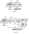
- FIG. 9A there is a block diagram of another embodiment of interference cancellation with an STTD decoder and a zero forcing STTD equalizer.
- the received signal R ⁇ of equation [33] is applied to via lead 900 to a whitening matched filter 902.
- This whitening matched filter includes the multiple finger matched filters 700-704 and their respective sampling STTD decoders 706-710 of FIG. 7 .
- a product of this received signal and the whitening matched filter is applied to a zero forcing STTD equalizer circuit 904 to produce data symbol matrix D ⁇ at lead 906.
- Equation [33] The term inside the zero forcing STTD equalizer circuit 904 yields a zero forcing solution to equation [33] without any intersymbol interference (ISI) or multiple access interference (MAI) as given in equation [34], where ⁇ ⁇ , ⁇ is the covariance of the noise vector ⁇ . and (.) H denotes the Hermitian operation on a matrix.
- ISI intersymbol interference
- MAI multiple access interference
- D ⁇ ⁇ D ⁇ ⁇ * ZF - STTD A ⁇ H ⁇ ⁇ N ⁇ , N ⁇ - 1 ⁇ A ⁇ - 1 ⁇ A ⁇ H ⁇ ⁇ N ⁇ , N ⁇ - 1 ⁇ R ⁇
- D ⁇ ⁇ D ⁇ ⁇ * ZF - STTD A ⁇ H ⁇ A ⁇ - 1 ⁇ A ⁇ H ⁇ R ⁇ since D ⁇ and D ⁇ x yield the same estimate for received data symbols, it is only necessary to calculate one of them.
- the Cholesky formulation of equation [36] provides a means for solving equation [35] using a forward equation obtained from the upper triangular matrix H.
- the detailed block diagram of FIG. 9B illustrates the iterative solution to equation [34] of the zero forcing STTD equalizer with decision feedback. Derivation and use of the feedback operator 924 is explained in detail Anja Klein et al. at 280.
- FIG. 10A there is a block diagram of a third embodiment of interference cancellation with an STTD decoder and a minimum mean squared error STTD equalizer.
- MMSE-STTD minimum mean squared error solution for STTD decoding
- FIG. 11 there is a simulation diagram showing bit error rate (BER) as a function of bit energy to noise (Eb/N 0 ) with and without diversity for vehicular Doppler rates with a spreading factor of 16.
- BER bit error rate
- FIG. 12 shows bit error rate (BER) as a function of bit energy to noise (Eb/N 0 ) with and without diversity for pedestrian Doppler rates with a spreading factor of 16 and 8 users. Both curves show improved bit energy to noise ratios compared to the simulation of FIG. 11 for the relatively higher vehicular Doppler rate.
- the STTD curve for a pedestrian Doppler rate shows a 3 dB improvement over the solid curve without STTD.
- STTD for TDD provides significantly improved reception over systems of the prior art.
- FIG. 13A there is a block diagram of a receiver including STTD decoders before the rake receivers and joint detector.
- This circuit design is similar to that of FIG. 7 .
- the circuit provides STTD decoder circuits 1302-1304 corresponding to respective multipath signals.
- Each STTD decoder produces plural output signals that are coupled to respective rake receivers to combine multipath signals for each respective user.
- the combined signals are then applied to joint STTD detector circuit 1310.
- the joint detector circuit utilizes detected signals for other users to eliminate interference from the intended user signal as previously described.
- the circuit of FIG. 13B is an alternative embodiment. This embodiment includes rake receivers 1312-1314 arranged to combine multipath signals for each respective user.
- the joint detector 1316 decodes the received signals for each user and subtracts interference signals for unintended users to produce the intended output signal Do on lead 1320.
- the circuit of FIG. 13C is yet another embodiment. This embodiment includes rake receivers 1312-1314 as previously described. Combined signals from the rake receivers are applied to the joint detector circuit 1318 for user identification and interference cancellation. The resulting signal is applied to STTD decoder 1319. The STTD decoder produces decoded output signal Do on lead 1320 for the intended user.
Landscapes
- Engineering & Computer Science (AREA)
- Computer Networks & Wireless Communication (AREA)
- Signal Processing (AREA)
- Radio Transmission System (AREA)
- Mobile Radio Communication Systems (AREA)
Claims (11)
- Eine Schaltung, gekennzeichnet durch:ein angepasstes Filter (600-604; 700-704) konfiguriert, um ein Mehrwegeingangssignal zu empfangen, das aus einem ersten Datensymbol (S1) und einer Transformation eines zweiten Datensymbols (-S2*) bei einer ersten Zeit besteht, die angepasste Filterschaltung besteht aus einer Vielzahl von Fingern, jeder Finger entspricht einem jeweiligen Weg von dem Mehrwegeingangsignal und jeder wird konfiguriert, um ein jeweiliges Ausgangssignal zu erzeugen;eine Vielzahl von Dekodern (606-610; 706-710; 1302-1304), jeder konfiguriert, um das Ausgangssignal von einem jeweiligen einem der Vielzahl von Fingern zu empfangen, jeder Dekoder konfiguriert zur Erzeugung eines dekodierten ersten Datensymbols und eines dekodierten zweiten Datensymbols für seinen jeweiligen Weg in Reaktion auf das erste Datensymbol (S1) und die Transformation des zweiten Datensymbols (-S2*); undeine gemeinsame Detektorschaltung (612, 712, 1310) konfiguriert, um die Vielzahl von dekodierten ersten und zweiten Datensymbolen zu empfangen und zur Verbindung der Vielzahl von ersten und zweiten dekodierten Datensymbolen, damit ein Ausgangssignal nach einem vorhergehenden Kode erzeugt wird.
- Eine Schaltung nach Anspruch 1, wobei die Transformation des zweiten Datensymbols (-S2*) eine komplexe Konjugation des zweiten Datensymbols ist.
- Eine Schaltung nach Ansprüchen 1 oder 2, wobei die gemeinsame Detektorschaltung (612, 712; 1310) aus einem Rakekombinierer besteht.
- Eine Schaltung nach allen vorhergehenden Ansprüchen, wobei jeder Finger (L) des angepassten Filters (700-704) so geordnet ist, eine Vielzahl (K) von jeweiligen Signalen entpsrechend einer Vielzahl von Anwender zu empfangen.
- Eine Schaltung nach allen vorhergehenden Ansprüchen, wobei die Vielzahl von Dekodern (606-610; 706-710; 1302-1304) dazu geordnet sind, eine Transformation des ersten Datensymbols (-S1*) und des zweiten Datensymbols (S2) bei einer zweiten Zeit zu empfangen.
- Eine Schaltung nach den Ansprüchen 1 - 5, wobei die gemeinsame Detektorschaltung (612, 712, 1310) zum Störungdämpfen durch parallele Störungsannullierung angeordnet ist.
- Eine Schaltung nach den Ansprüchen 1 - 5, wobei die gemeinsame Detektorschaltung (612, 712, 1310) zum Störungdämpfen durch Zero-Forcing-Störungsannullierung angeordnet ist.
- Eine Schaltung nach den Ansprüchen 1 - 5, wobei die gemeinsame Detektorschaltung (612, 712, 1310) zum Störungdämpfen durch MMSE - Störungsannullierung angeordnet ist.
- Eine Schaltung nach allen vorhergehenden Ansprüchen, wobei ein vorhergehender Kode einem Fahrzeugempfanger entspricht.
- Eine Schaltung nach allen vorhergehenden Ansprüchen, wobei der vorhergehende Kode aus einer Teilmenge von einer Kodefolge besteht, die einer Vielzahl von Farhzeugempfangern entpsricht.
- Eine Schaltung nach allen vorhergehenden Ansprüchen dazu bestehend aus einer Vielzahl von Rake-Empfangern (1312 - 1314), jeder Rake-Empfanger gekoppelt zwischen einem jeweiligen Dekoder (1302-1304) und der gemeinsamen Detektorschaltung.
Applications Claiming Priority (2)
| Application Number | Priority Date | Filing Date | Title |
|---|---|---|---|
| US12154199P | 1999-02-25 | 1999-02-25 | |
| US121541P | 2000-02-25 |
Publications (3)
| Publication Number | Publication Date |
|---|---|
| EP1133071A2 EP1133071A2 (de) | 2001-09-12 |
| EP1133071A3 EP1133071A3 (de) | 2005-05-18 |
| EP1133071B1 true EP1133071B1 (de) | 2014-05-21 |
Family
ID=22397366
Family Applications (1)
| Application Number | Title | Priority Date | Filing Date |
|---|---|---|---|
| EP20000200670 Expired - Lifetime EP1133071B1 (de) | 1999-02-25 | 2000-02-25 | Raum-Zeit-Sendediversität für TDD/WCDMA Systeme |
Country Status (1)
| Country | Link |
|---|---|
| EP (1) | EP1133071B1 (de) |
Families Citing this family (9)
| Publication number | Priority date | Publication date | Assignee | Title |
|---|---|---|---|---|
| WO2003036810A1 (de) * | 2001-09-28 | 2003-05-01 | Siemens Aktiengesellschaft | Vorrichtung und verfahren zum entzerren von empfangssignalen |
| US7085332B2 (en) | 2001-12-14 | 2006-08-01 | Ericsson, Inc. | Method and apparatus for two-user joint demodulation in a system having transmit diversity |
| GB2384660B (en) * | 2002-01-25 | 2004-11-17 | Toshiba Res Europ Ltd | Reciever processing systems |
| SE0201103D0 (sv) * | 2002-04-11 | 2002-04-11 | Ericsson Telefon Ab L M | Diagonally Layered Multi-Antenna Transmission for Frequency Selective Channels |
| JP3581356B2 (ja) | 2002-05-22 | 2004-10-27 | 松下電器産業株式会社 | 通信端末装置及び拡散コード推定方法 |
| CN1170374C (zh) * | 2002-06-20 | 2004-10-06 | 大唐移动通信设备有限公司 | 一种适用于频率选择性衰落信道的空时编译码方法 |
| EP1453262A1 (de) * | 2003-02-28 | 2004-09-01 | Mitsubishi Electric Information Technology Centre Europe B.V. | Iterative MMSE-Erfassung |
| FR2859333A1 (fr) * | 2003-09-01 | 2005-03-04 | France Telecom | Procede de decodage d'un signal code a l'aide d'une matrice de codage espace-temps, recepteur et procede de codage et de decodage correspondants |
| CN103248377B (zh) * | 2013-05-15 | 2014-12-10 | 哈尔滨工业大学 | 多载波互补码cdma系统的接收端信号干扰消除方法 |
Family Cites Families (3)
| Publication number | Priority date | Publication date | Assignee | Title |
|---|---|---|---|---|
| JP2846860B2 (ja) * | 1996-10-01 | 1999-01-13 | ユニデン株式会社 | スペクトル拡散通信方式を用いた送信機、受信機、通信システム及び通信方法 |
| US6356605B1 (en) * | 1998-10-07 | 2002-03-12 | Texas Instruments Incorporated | Frame synchronization in space time block coded transmit antenna diversity for WCDMA |
| EP1056237B1 (de) * | 1999-04-08 | 2014-01-22 | Texas Instruments Incorporated | Diversitätsdetektion für WCDMA |
-
2000
- 2000-02-25 EP EP20000200670 patent/EP1133071B1/de not_active Expired - Lifetime
Also Published As
| Publication number | Publication date |
|---|---|
| EP1133071A3 (de) | 2005-05-18 |
| EP1133071A2 (de) | 2001-09-12 |
Similar Documents
| Publication | Publication Date | Title |
|---|---|---|
| US6775260B1 (en) | Space time transmit diversity for TDD/WCDMA systems | |
| EP0993130B1 (de) | Raum-Zeit blockkodierte Sendeantennediversity für WCDMA | |
| US7136410B2 (en) | Adaptive interference suppression receiving apparatus for space-time block coded direct sequence/code division multiple access communication system | |
| US7020175B2 (en) | MMSE reception of DS-CDMA with transmit diversity | |
| US7583723B2 (en) | Method and apparatus providing an advanced MIMO receiver that includes a signal-plus-residual interference (SPRI) detector | |
| US7324583B2 (en) | Chip-level or symbol-level equalizer structure for multiple transmit and receiver antenna configurations | |
| US20040028121A1 (en) | Receiver processing systems | |
| US20060182193A1 (en) | Technique for adaptive equalization in band-limited high data rate communication over fading dispersive channels | |
| US20040017843A1 (en) | Receiver processing systems | |
| US6724828B1 (en) | Mobile switching between STTD and non-diversity mode | |
| US6424642B1 (en) | Estimation of doppler frequency through autocorrelation of pilot symbols | |
| EP1006676A2 (de) | Rahmensynchronisation in Raum-Zeit blockkodierte Sendeantennendiversity für WCDMA | |
| US7606318B2 (en) | Method of space-time encoding and decoding for frequency selective fading channel | |
| US20030072282A1 (en) | Code division multiple access downlink receiver | |
| EP0993129B1 (de) | Kanalschätzung in Raum-Zeit blockkodierter Sendeantennendiversität für WCDMA | |
| US20080089403A1 (en) | Chip-level or symbol-level equalizer structure for multiple transmit and receiver antenna configurations | |
| EP1133071A2 (de) | Raum-Zeit-Sendediversität für TDD/WCDMA Systeme | |
| JP2000315966A (ja) | Tdd/wcdmaのための空間時間送信ダイバーシチ | |
| Wales | A mimo technique within the UTRA TDD standard | |
| Phoel et al. | Transmitter diversity for DS-CDMA with MMSE decision feedback | |
| Guncavdi et al. | Space-time pre-RAKE multiuser transmitter precoding for DS-CDMA systems | |
| Guncavdi | Transmitter diversity and multiuser precoding for Rayleigh fading code division multiple access channels | |
| Kopsa et al. | Performance of multiple antenna combining algorithms in the uplink of UTRA/FDD | |
| Jungnickel et al. | A MIMO RAKE receiver with enhanced interference cancellation | |
| EP1341319A1 (de) | Datenverarbeitungsverfahren und korrespondierende Basisstation mit mehreren Antennen |
Legal Events
| Date | Code | Title | Description |
|---|---|---|---|
| PUAI | Public reference made under article 153(3) epc to a published international application that has entered the european phase |
Free format text: ORIGINAL CODE: 0009012 |
|
| AK | Designated contracting states |
Kind code of ref document: A2 Designated state(s): AT BE CH CY DE DK ES FI FR GB GR IE IT LI LU MC NL PT SE |
|
| AX | Request for extension of the european patent |
Free format text: AL;LT;LV;MK;RO;SI |
|
| RIC1 | Information provided on ipc code assigned before grant |
Ipc: 7H 04B 1/707 B Ipc: 7H 04L 1/06 B Ipc: 7H 04B 7/06 A |
|
| PUAL | Search report despatched |
Free format text: ORIGINAL CODE: 0009013 |
|
| AK | Designated contracting states |
Kind code of ref document: A3 Designated state(s): AT BE CH CY DE DK ES FI FR GB GR IE IT LI LU MC NL PT SE |
|
| AX | Request for extension of the european patent |
Extension state: AL LT LV MK RO SI |
|
| 17P | Request for examination filed |
Effective date: 20051118 |
|
| AKX | Designation fees paid |
Designated state(s): DE FR GB |
|
| 17Q | First examination report despatched |
Effective date: 20080625 |
|
| GRAP | Despatch of communication of intention to grant a patent |
Free format text: ORIGINAL CODE: EPIDOSNIGR1 |
|
| INTG | Intention to grant announced |
Effective date: 20140102 |
|
| GRAS | Grant fee paid |
Free format text: ORIGINAL CODE: EPIDOSNIGR3 |
|
| GRAA | (expected) grant |
Free format text: ORIGINAL CODE: 0009210 |
|
| AK | Designated contracting states |
Kind code of ref document: B1 Designated state(s): DE FR GB |
|
| REG | Reference to a national code |
Ref country code: GB Ref legal event code: FG4D |
|
| REG | Reference to a national code |
Ref country code: DE Ref legal event code: R096 Ref document number: 60048577 Country of ref document: DE Effective date: 20140703 |
|
| REG | Reference to a national code |
Ref country code: FR Ref legal event code: PLFP Year of fee payment: 16 |
|
| REG | Reference to a national code |
Ref country code: DE Ref legal event code: R097 Ref document number: 60048577 Country of ref document: DE |
|
| PLBE | No opposition filed within time limit |
Free format text: ORIGINAL CODE: 0009261 |
|
| STAA | Information on the status of an ep patent application or granted ep patent |
Free format text: STATUS: NO OPPOSITION FILED WITHIN TIME LIMIT |
|
| 26N | No opposition filed |
Effective date: 20150224 |
|
| PGFP | Annual fee paid to national office [announced via postgrant information from national office to epo] |
Ref country code: DE Payment date: 20150227 Year of fee payment: 16 |
|
| PGFP | Annual fee paid to national office [announced via postgrant information from national office to epo] |
Ref country code: FR Payment date: 20150126 Year of fee payment: 16 |
|
| REG | Reference to a national code |
Ref country code: DE Ref legal event code: R097 Ref document number: 60048577 Country of ref document: DE Effective date: 20150224 |
|
| PGFP | Annual fee paid to national office [announced via postgrant information from national office to epo] |
Ref country code: GB Payment date: 20160127 Year of fee payment: 17 |
|
| REG | Reference to a national code |
Ref country code: DE Ref legal event code: R119 Ref document number: 60048577 Country of ref document: DE |
|
| REG | Reference to a national code |
Ref country code: FR Ref legal event code: ST Effective date: 20161028 |
|
| PG25 | Lapsed in a contracting state [announced via postgrant information from national office to epo] |
Ref country code: FR Free format text: LAPSE BECAUSE OF NON-PAYMENT OF DUE FEES Effective date: 20160229 Ref country code: DE Free format text: LAPSE BECAUSE OF NON-PAYMENT OF DUE FEES Effective date: 20160901 |
|
| GBPC | Gb: european patent ceased through non-payment of renewal fee |
Effective date: 20170225 |
|
| PG25 | Lapsed in a contracting state [announced via postgrant information from national office to epo] |
Ref country code: GB Free format text: LAPSE BECAUSE OF NON-PAYMENT OF DUE FEES Effective date: 20170225 |