EP1133080A1 - Dispositif de communication radio et methode de commande d'antennes - Google Patents
Dispositif de communication radio et methode de commande d'antennes Download PDFInfo
- Publication number
- EP1133080A1 EP1133080A1 EP00961042A EP00961042A EP1133080A1 EP 1133080 A1 EP1133080 A1 EP 1133080A1 EP 00961042 A EP00961042 A EP 00961042A EP 00961042 A EP00961042 A EP 00961042A EP 1133080 A1 EP1133080 A1 EP 1133080A1
- Authority
- EP
- European Patent Office
- Prior art keywords
- transmission data
- radio communication
- communication apparatus
- antennas
- switching
- Prior art date
- Legal status (The legal status is an assumption and is not a legal conclusion. Google has not performed a legal analysis and makes no representation as to the accuracy of the status listed.)
- Withdrawn
Links
Images






Classifications
-
- H—ELECTRICITY
- H04—ELECTRIC COMMUNICATION TECHNIQUE
- H04B—TRANSMISSION
- H04B7/00—Radio transmission systems, i.e. using radiation field
- H04B7/14—Relay systems
- H04B7/15—Active relay systems
- H04B7/155—Ground-based stations
-
- H—ELECTRICITY
- H04—ELECTRIC COMMUNICATION TECHNIQUE
- H04B—TRANSMISSION
- H04B7/00—Radio transmission systems, i.e. using radiation field
- H04B7/02—Diversity systems; Multi-antenna system, i.e. transmission or reception using multiple antennas
- H04B7/04—Diversity systems; Multi-antenna system, i.e. transmission or reception using multiple antennas using two or more spaced independent antennas
- H04B7/06—Diversity systems; Multi-antenna system, i.e. transmission or reception using multiple antennas using two or more spaced independent antennas at the transmitting station
- H04B7/0602—Diversity systems; Multi-antenna system, i.e. transmission or reception using multiple antennas using two or more spaced independent antennas at the transmitting station using antenna switching
- H04B7/0604—Diversity systems; Multi-antenna system, i.e. transmission or reception using multiple antennas using two or more spaced independent antennas at the transmitting station using antenna switching with predefined switching scheme
-
- H—ELECTRICITY
- H04—ELECTRIC COMMUNICATION TECHNIQUE
- H04B—TRANSMISSION
- H04B7/00—Radio transmission systems, i.e. using radiation field
- H04B7/02—Diversity systems; Multi-antenna system, i.e. transmission or reception using multiple antennas
- H04B7/12—Frequency diversity
Definitions
- the present invention relates to a radio communication apparatus and antenna control method, and more particularly, to a radio communication apparatus provided with a plurality of antennas and a method for controlling the plurality of antennas.
- a base station transmits respective different information to a plurality of (N) mobile stations such as a radio communication service system
- the base station is provided with a plurality of antennas, and concurrently transmits different information to a plurality of mobile stations with respective antennas.
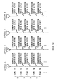
- FIG.1 is a diagram illustrating a situation where data is transmitted from a plurality of antennas provided in the conventional base station apparatus.
- the base station apparatus is provided with a plurality of antennas (herein, the number of antennas is assumed to be "4").
- the base station apparatus concurrently transmits transmission data A at a carrier frequency fA from an antenna A, transmission data B at a carrier frequency fB from an antenna B, transmission data C at a carrier frequency fC from an antenna C, and transmission data D at a carrier frequency fD from an antenna D.
- the conventional base station apparatus does not provide the effect of the diversity in the case where the number of antennas of a mobile station on a receiving side is "1". That is, if the number of antennas of a mobile station is a plural number, the diversity effect can be obtained by the space diversity. However, the number of antennas of a mobile station is generally "1", and in this case, the diversity effect cannot be obtained. In particular, when the fading rate is low, an interval where a received level falls down lasts a long time, and therefore the diversity effect cannot be obtained.
- a plurality of kinds of transmission data are switched timewise sequentially between a plurality of antennas provided in the radio communication apparatus to be transmitted.
- a radio communication apparatus and antenna control method perform frequency conversion on a plurality of kinds of data with respective specific carrier frequencies, and timewise switch data sequentially between a plurality of antennas provided in the radio communication apparatus to transmit.
- FIG.2 is a general block diagram illustrating a schematic configuration of the radio communication apparatus according to the first embodiment of the present invention.
- coding section 101 codes four kinds of transmission data A to D.
- Modulating section 102 performs predetermined modulation processing on the coded transmission data A to D.
- Radio section 103 multiplies the modulated transmission data A to D respectively by a carrier with a frequency of fA, fB, fC or fD, thereby performs the frequency conversion, and outputs the resultant signals to switch 104.
- Switch 104 switches between frequency conversion sections fA to fD in radio section 103 and between antennas A to D to connect.
- the radio communication apparatus is comprised of four frequency conversion sections fA to fD and four antennas A to D, so that the radio communication apparatus according to this embodiment transmits transmission data A to D respectively to four communication stations A to D (i.e., transmission data A to communication station A and the like). That is, in this embodiment, the radio communication apparatus is assumed to be used in a one-to-four communication system where one radio communication apparatus transmits respective different transmission data to four communication stations using four antennas.
- Timing control section 105 outputs a timing control signal to switching control section 107 at time intervals for which timer 106 is preset.
- Switching control section 107 controls the switching of switch 104 according to switching patterns which are preset in switching pattern storage section 108 and which are each indicative of a connection relationship between antennas A to D and each of frequency conversion sections fA to fD.
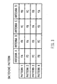
- FIG.3 is a diagram illustrating an example of the switching patterns preset in the switching pattern storage section in the radio communication apparatus according to the first embodiment of the present invention.
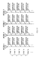
- FIG.4 is a diagram illustrating a situation where data is transmitted from each antenna of the radio communication apparatus according to the first embodiment of the present invention.
- the transmission data A to D subjected to the predetermined modulation processing in modulating section 102 are output to radio section 103. Then, the transmission data A to D are multiplied by the carrier of frequency fA, fB, fC or fD in frequency conversion sections fA to fD, respectively, thereby being subjected to the frequency conversion, and the signal with each of the frequencies fA to fD is output to switch 104.
- Timer 106 is set for predetermined times, and according to the constant time intervals, timing control section 105 outputs the timing control signal to switching control section 107. Specifically, time 106 is preset for times T illustrated in FIG.4. In other words, timing control section 105 outputs the timing control signal at times T1, T2, T3, T4, ⁇ .
- switching control section 107 refers to switching pattern storage section 108, and controls the switching of switch 104.
- the switching patterns as illustrated in FIG.3 are preset in switching pattern storage section 108.
- switching control section 107 refers to one of patterns 1 to 4 sequentially. That is, at time T1, switching control section 107 refers to the pattern 1 and according to this pattern, switches switch 104.
- switching control section 107 refers to the pattern 2, pattern 3, and pattern 4 respectively at time T2, time T3 and time T4, and according to each pattern, switches switch 104.
- switching control section 107 refers to the pattern 1 again, and continues the similar processing as described above thereafter.
- transmission data A to D respectively with the carrier frequencies fA to fD are switched to be sequentially transmitted from one of antennas A to D.
- the transmission data A with the carrier frequency fA, the transmission data B with the carrier frequency fB, the transmission data C with the carrier frequency fC, and the transmission data D with the carrier frequency fD are transmitted at the same time respectively from antennas A, B, C and D.
- the transmission data D with the carrier frequency fD, the transmission data A with the carrier frequency fA, the transmission data B with the carrier frequency fB, and the transmission data C with the carrier frequency fC are transmitted at the same time respectively from antennas A, B, C and D.
- transmission data A to D with the respective carrier frequencies fA to fD are switched sequentially between antennas A to D to be transmitted therefrom.
- a plurality of kinds of transmission data are subjected to the frequency conversion with the respective specific carrier frequencies, and are switched timewise sequentially to be transmitted between a plurality of antennas provided in the radio communication apparatus, whereby on a receiving side, if a received level of data falls down which is transmitted from some antenna, it is possible to receive the same kind of data transmitted from another antenna at the following time. Accordingly, the rate that the received level falls down is decreased, and therefore the receiving side is able to obtain the excellent diversity effect even in the case where the number of antennas on the receiving side is "1". Further, even when the fading rate is low, since it is possible to receive at the following time the same kind of data transmitted from another antenna, it is possible to obtain the diversity effect.
- a radio communication apparatus and antenna control method according to this embodiment are different from those of the first embodiment in a point that a switching pattern repeating period is made equal to a time interleaving length of FEC (Forward Error Correction).
- FEC Forward Error Correction
- FIG.5 is a diagram illustrating a situation where data is transmitted from each antenna of the radio communication apparatus according to the second embodiment of the present invention.
- time interleaving length of FEC is herein indicative of a period of time at which data subjected to convolutional coding is divided to be transmitted.
- switching patterns are set such that the number of divided items of data subjected to convolutional coding is equal to the number of switching patterns. Specifically, for example, assuming the number of divided items is "4", as illustrated in FIG.3, four patterns, i.e., patterns 1 to 4, are set as switching patterns.
- timer 106 is preset for a time T so that the switching pattern repeating period is equal to the time interleaving length TI of FEC. In other words, when there are four kinds of transmission data A to D, the time T is set at one-fourth the time interleaving length.
- the switching pattern at time T1 is the same as the switching pattern at time T5 when the time interleaving length TI has elapsed after time T1. Thereafter, using the time interleaving length TI as the switching pattern repeating period, the switching of switch 104 is controlled.
- a plurality of kinds of transmission data are subjected to the frequency conversion with the respective specific carrier frequencies, and are switched timewise sequentially to be transmitted between a plurality of antennas provided in the radio communication apparatus, and the switching pattern repeating period is made equal to the time interleaving length of FEC, whereby the error randomizing due to the effect of transmitting data using a plurality of antennas is added to the error randomizing due to the interleaving effect.
- the switching pattern repeating period is made equal to the time interleaving length of FEC, whereby the error randomizing due to the effect of transmitting data using a plurality of antennas is added to the error randomizing due to the interleaving effect.
- a radio communication apparatus and antenna control method according to this embodiment are different from those of the first embodiment in a point that switching patterns are set so as to switch transmission data between antennas having low antenna correlation with each other.
- FIG.6 is a diagram illustrating an example of switching patterns preset in a switching pattern storage section in the radio communication apparatus according to the third embodiment of the present invention.
- FIG.7 is a diagram illustrating a situation where data is transmitted from each antenna of the radio communication apparatus according to the third embodiment of the present invention.
- the "antenna correlation" is herein indicative of cross-correlation between antennas.
- the switching is performed without considering the degree of the antenna correlation, and therefore it may happen that even when the transmission data is transmitted while switching the antennas, the fading similar to that before the switching occurs.
- the data items transmitted from different antennas are considered on the receiving side to be transmitted through different propagation paths. Accordingly, if a received level falls down of data transmitted from some antenna, it is considered that another received level does not fall down of the same kind of data transmitted from another antenna having the low antenna correlation.
- switching pattern storage section 108 is set for switching patterns such that transmission data is switched between antennas having the low antenna correlation with each other.
- the switching patterns become as illustrated in FIG.6.
- the switching patterns are set so that transmission data A and D are switched between the antennas A and D having the low antenna correlation, and that transmission data B and C are switched between the antennas B and C having the low antenna correlation.
- switching control section 107 controls at time T1 the switching of switch 104 according to the pattern 1 illustrated in FIG.6, and at time T2, controls the switching of switch 104 according to the pattern 2 illustrated in FIG.6. Then, at time T3, switching control section 107 controls the switching of switch 104 again according to the pattern 1 illustrated in FIG.6. The similar operation is repeated thereafter.
- transmission data A with the carrier frequency fA, transmission data B with the carrier frequency fB, transmission data C with the carrier frequency fC, and transmission data D with the carrier frequency fD are transmitted at the same time respectively from antennas A, B, C and D.
- transmission data D with the carrier frequency fD, transmission data C with the carrier frequency fC, transmission data B with the carrier frequency fB, and transmission data A with the carrier frequency fA are transmitted at the same time respectively from antennas A, B, C and D.
- the data is switched between the antennas having the low antenna correlation with each other, in other words, transmission data A and D are switched between the antennas A and D having the low antenna correlation, while transmission B and C are switched between the antennas B and C having the low antenna correlation.
- a plurality of kinds of transmission data are subjected to the frequency conversion with the respective specific carrier frequencies, and are switched timewise sequentially to be transmitted between a plurality of antennas provided in the radio communication apparatus, and the switching patterns are set so that transmission data is switched between antennas having the low antenna correlation with each other. Therefore, as compared to the first embodiment, it is possible to increase the reliability for obtaining the diversity effect and to improve the error correcting capability.
- a radio communication apparatus and antenna control method are different from those of the first embodiment in a point that a plurality of kinds of transmission data in digital baseband state is assigned to each antenna sequentially before being converted to a signal with the carrier frequency of a high frequency.
- FIG.8 is a general block diagram illustrating a schematic configuration of the radio communication apparatus according to the fourth embodiment of the present invention.
- the same sections as those in the first embodiment are assigned the same reference numerals and the detailed explanation is omitted.
- switch 701 switches between synthesizers S1 to S4 in radio section 702 to connect to modulating section 102.
- Switching control section 703 controls the switching of switch 701 according to switching patterns which are preset in switching pattern storage section 704 and which are each indicative of a connection relationship between transmission data A to D and each of synthesizers S1 to S4.
- the radio communication apparatus is comprised of four synthesizers S1 to S4 and four antennas A to D, so that the radio communication apparatus according to this embodiment transmits transmission data A to D respectively to four communication stations A to D (i.e., transmission data A to communication station A and the like). That is, in this embodiment, the radio communication apparatus is assumed to be used in a one-to-four communication system where one radio communication apparatus transmits respective different transmission data to four communication stations using four antennas.
- FIG.9 is a diagram illustrating an example of the switching patterns preset in the switching pattern storage section in the radio communication apparatus according to the fourth embodiment of the present invention.
- FIG.10 is a diagram illustrating timings at which each synthesizer switches carrier frequencies in the radio communication apparatus according to the fourth embodiment of the present invention.
- FIG.11 is a diagram illustrating a situation where data is transmitted from each antenna of the radio communication apparatus according to the fourth embodiment of the present invention.
- the transmission data A to D subjected to the predetermined modulation processing in modulating section 102 are output in the baseband state to switch 701. Accordingly, each of the transmission data A to D is assigned to a respective antenna A, B, C or D in the baseband state before being subjected to the frequency conversion.
- switching control section 703 refers to switching pattern storage section 704, and controls the switching of switch 701.
- switching pattern storage section 704 are preset for the switching pattern as illustrated in FIG.9.
- switching control section 703 refers to one of patterns 1 to 4 sequentially. That is, at time T1, switching control section 703 refers to the pattern 1 and according to this pattern, switches switch 701. Similarly, switching control section 703 refers to the pattern 2, pattern 3, and pattern 4 respectively at time T2, time T3 and time T4, and according to each pattern, switches switch 701. Further, at time T5, switching control section 703 refers to the pattern 1 again, and continues the similar processing as described above thereafter.
- the transmission data A, transmission data B, transmission data C and transmission data D are input at the same time respectively to synthesizers S1, S2, S3 and S4. Further, at time T2, the transmission data D, transmission data A, transmission data B, and the transmission data C are input at the same time respectively to synthesizers S1, S2, S3 and S4. Thereafter in the similar way, transmission data to be input to each synthesizer is switched sequentially.
- switching control section 703 controls the switching of carrier frequencies of synthesizers S1 to S4. Specifically, according to timings as illustrated in FIG.10, the switching of the carrier frequencies is controlled.
- synthesizers S1, S2, S3 and S4 perform frequency conversion on input transmission data respectively with the carrier frequency fA, carrier frequency fB, carrier frequency fC, and the carrier frequency fD.
- synthesizers S1, S2, S3 and S4 perform frequency conversion on input transmission data respectively with the carrier frequency fD, carrier frequency fA, carrier frequency fB, and the carrier frequency fC.
- the similar processing is repeated.
- transmission data A to D with the respective carrier frequencies fA to fD are switched sequentially between antennas A to D to be transmitted therefrom.
- transmission data A to D with the respective carrier frequencies fA to fD are switched sequentially between antennas A to D to be transmitted therefrom.
- a plurality of kinds of transmission data in digital baseband state is assigned to each antenna sequentially before being converted to a signal with the carrier frequency of a high frequency. Therefore, as compared to the case that the transmission data is converted to a signal with the carrier frequency and that the resultant signal is assigned to each antenna, it is possible to decrease losses of, for example, power of transmission data occurring due to the switching operation.
- a radio communication apparatus and antenna control method according to this embodiment are different from those of the fourth embodiment in a point that a plurality of synthesizers is provided for an antenna so as to switch a carrier frequency of a synthesizer while another synthesizer performs the frequency conversion.
- each of antennas A to D is assigned one of synthesizers S1 to S4, and one synthesizer corresponding to each antenna switches between carrier frequencies fA to fD sequentially.
- the synthesizer is an analog device, and it takes a time to some extent for the synthesizer to switch the carrier frequency. In other words, when the synthesizer switches the carrier frequency from fA to fB, it takes a time to some extent until the carrier frequency converges to the carrier frequency fB that is a goal frequency after being switched. Unless the carrier frequency is stable, it is not possible for a radio communication apparatus to perform stable data transmission.
- a synthesizer switches the carrier frequency while another synthesizer performs the frequency conversion on the transmission data. It is thereby possible for the synthesizer that is not performing the frequency conversion on the transmission data currently to switch the carrier frequency with a sufficient time given. Accordingly, such a synthesizer is able to perform the frequency conversion with the stable carrier frequency in performing the frequency conversion on the transmission data next time.
- FIG.12 is a general block diagram illustrating a schematic configuration of the radio communication apparatus according to the fifth embodiment of the present invention.
- the same sections as those in the fourth embodiment are assigned the same reference numerals and the detailed explanation is omitted.
- radio section 1101 is provided with S11 and S12 for the antenna A, with S21 and S22 for the antenna B, with S31 and S32 for the antenna C, and with S41 and S42 for the antenna D.
- a plurality of synthesizers is provided for a single antenna.
- this embodiment provides two synthesizers for a single antenna, however, the number of synthesizers is not limited to two, and it is only necessary that the number of synthesizers to be provided for a single antenna is plural.
- FIG.13 is a diagram illustrating timings at which each synthesizer switches carrier frequencies in the radio communication apparatus according to the fifth embodiment of the present invention.
- FIG.14 is a diagram illustrating a situation where data is transmitted from each antenna of the radio communication apparatus according to the fifth embodiment of the present invention.
- switching control section 703 controls the switching of carrier frequencies for S11 to S42. Specifically, at timings as illustrated in FIG.13, the section 703 controls the switching of carrier frequencies.
- the frequency switching operation on synthesizers S11 and S12 for the antenna A is the same as frequency switching operation on synthesizers S21 to S42 for the antenna B to D, and therefore, the frequency switching operation on synthesizers S11 and S12 for the antenna A will be only explained below.
- synthesizer S11 performs the frequency conversion on transmission data A with the carrier frequency fA. While synthesizer S11 is performing the frequency conversion on the transmission data A, synthesizer S12 switches the carrier frequency to fD.
- synthesizer S12 performs the frequency conversion on transmission data D with the carrier frequency fD.
- Synthesizer S12 was able to switch the carrier frequency to fD at time T1 in a sufficient time, whereby at time T2, the carrier frequency of synthesizer S12 has already converged to fD and is stable. While synthesizer S12 is performing the frequency conversion, synthesizer S11 switches the carrier frequency from fA to fC. At time T3 and thereafter, the similar operation is repeated.
- transmission data A to D with the respective carrier frequencies fA to fD are switched sequentially between antennas A to D to be transmitted therefrom.
- transmission data A to D with the respective carrier frequencies fA to fD are switched sequentially between antennas A to D to be transmitted therefrom.
- a plurality of synthesizers is provided for a single antenna, and a synthesizer switches the carrier frequency while another synthesizer performs the frequency conversion on the transmission data, whereby it is possible for the synthesizer that is not performing the frequency conversion on the transmission data currently to switch the carrier frequency with a sufficient time given. Accordingly, such a synthesizer is able to perform the frequency conversion with the stable carrier frequency in performing the frequency conversion on the transmission data next time. Accordingly, the radio communication apparatus is able to perform stable data transmission.
- the number of antennas (antennas A to D, i.e., "4") is made equal to the number of kinds of transmission data (transmission data A to D, i.e., "4"), however, it is not necessary that the number of antennas is equal to the number of kinds of transmission data. It addition, it is required that the number of antennas is one of the multiples or divisors of the number of kinds of transmission data.
- a kind of transmission data (for example, transmission data A) may be transmitted from a plurality of antennas (for example, antennas A and B) at the same time. Since the power of the transmission data is increased by thus performing, it is possible to improve the error correcting capability.
- the number of antennas is "8" and the number of kinds of transmission data is "4", it may be possible to assign five antennas to a kind of transmission data with a high priority, while assigning an antenna to each of other kinds of transmission data.
- the power of the transmission data with the high priority is thereby increased, whereby it is possible to further improve the error correcting capability on the transmission data with the high priority.
- a plurality of kinds of transmission data may be multiplexed and transmitted from an antenna (for example, antenna A) at the same time. It is thereby possible to decrease the number of transmission antennas, and therefore to reduce the scale of the apparatus.
- switching patterns explained above are examples, are not limited to those, and are capable of being modified as appropriate. Furthermore, in the above explanation, while switching intervals are set to constant time T, the switching intervals are not limited to that, and need not to be equal intervals.
- the present invention is not limited to the above-mentioned first to fifth embodiments, and is capable of being carried into practice with various modifications thereof. Further, in the present invention, the above-mentioned first to fifth embodiments are capable of being carried into practice in a combination thereof as appropriate.
- the present invention is applicable to a communication terminal apparatus and base station apparatus used in a one-to-N communication system where a transmitting-side apparatus provided with a plurality of antennas transmits respective different information to a plurality of (N) receiving-side apparatuses using the antennas, such as a radio communication service system.
Landscapes
- Engineering & Computer Science (AREA)
- Computer Networks & Wireless Communication (AREA)
- Signal Processing (AREA)
- Radio Transmission System (AREA)
- Variable-Direction Aerials And Aerial Arrays (AREA)
- Time-Division Multiplex Systems (AREA)
- Transmitters (AREA)
- Mobile Radio Communication Systems (AREA)
Applications Claiming Priority (5)
| Application Number | Priority Date | Filing Date | Title |
|---|---|---|---|
| JP26359999 | 1999-09-17 | ||
| JP26359999 | 1999-09-17 | ||
| JP33941199A JP3581282B2 (ja) | 1999-09-17 | 1999-11-30 | 基地局装置およびアンテナ制御方法 |
| JP33941199 | 1999-11-30 | ||
| PCT/JP2000/006339 WO2001022621A1 (fr) | 1999-09-17 | 2000-09-18 | Dispositif de communication radio et methode de commande d'antennes |
Publications (1)
| Publication Number | Publication Date |
|---|---|
| EP1133080A1 true EP1133080A1 (fr) | 2001-09-12 |
Family
ID=26546096
Family Applications (1)
| Application Number | Title | Priority Date | Filing Date |
|---|---|---|---|
| EP00961042A Withdrawn EP1133080A1 (fr) | 1999-09-17 | 2000-09-18 | Dispositif de communication radio et methode de commande d'antennes |
Country Status (7)
| Country | Link |
|---|---|
| US (1) | US6931238B1 (fr) |
| EP (1) | EP1133080A1 (fr) |
| JP (1) | JP3581282B2 (fr) |
| KR (1) | KR100413151B1 (fr) |
| CN (1) | CN1152487C (fr) |
| AU (1) | AU7314600A (fr) |
| WO (1) | WO2001022621A1 (fr) |
Cited By (3)
| Publication number | Priority date | Publication date | Assignee | Title |
|---|---|---|---|---|
| WO2003081804A1 (fr) | 2002-03-21 | 2003-10-02 | Lg Electronics Inc. | Dispositif et procede permettant de transmettre un signal dans un systeme de communication mobile |
| EP1618678A4 (fr) * | 2003-04-29 | 2010-03-31 | Lg Electronics Inc | Procede de transmission de signal dans un systeme de communication mobile |
| WO2011140149A3 (fr) * | 2010-05-03 | 2012-01-12 | Qualcomm Incorporated | Activation conditionnelle d'ultd en fonction de l'ue |
Families Citing this family (12)
| Publication number | Priority date | Publication date | Assignee | Title |
|---|---|---|---|---|
| US8090381B2 (en) * | 2001-11-20 | 2012-01-03 | At&T Intellectual Property Ii, L.P. | Protocol assisted switched diversity of antennas |
| JP4583096B2 (ja) * | 2004-07-29 | 2010-11-17 | 京セラ株式会社 | 無線通信装置、通信態様変更方法及びプログラム |
| JP4065276B2 (ja) * | 2004-11-12 | 2008-03-19 | 三洋電機株式会社 | 送信方法およびそれを利用した無線装置 |
| US7558335B2 (en) * | 2005-02-10 | 2009-07-07 | Interdigital Technology Corporation | Communication system modulating/demodulating data using antenna patterns and associated methods |
| EP1865618A4 (fr) | 2005-03-30 | 2012-05-02 | Fujitsu Ltd | Terminal mobile, appareil et procede de communication sans fil |
| US7738356B2 (en) * | 2005-06-28 | 2010-06-15 | Broadcom Corporation | Multiple stream cyclic-shifted delay transmitter |
| JP3989512B2 (ja) * | 2005-09-15 | 2007-10-10 | 三洋電機株式会社 | 無線装置 |
| EP2345176A1 (fr) * | 2008-10-09 | 2011-07-20 | Telefonaktiebolaget L M Ericsson (PUBL) | Agencement d'antenne pour communication à flux multiples dans un canal mimo |
| JP5826065B2 (ja) * | 2011-10-27 | 2015-12-02 | 三菱電機株式会社 | 受信装置および通信装置 |
| JP6048091B2 (ja) * | 2011-12-28 | 2016-12-21 | 株式会社リコー | 通信装置、通信方法および通信プログラム |
| JP2015185214A (ja) * | 2014-03-20 | 2015-10-22 | セイコーエプソン株式会社 | コネクター、無線通信モジュール、無線通信装置、及び、電子機器 |
| JP2018022339A (ja) * | 2016-08-03 | 2018-02-08 | 富士通株式会社 | 演算処理装置及び演算処理装置の制御方法 |
Family Cites Families (10)
| Publication number | Priority date | Publication date | Assignee | Title |
|---|---|---|---|---|
| US3922685A (en) * | 1973-07-30 | 1975-11-25 | Motorola Inc | Antenna pattern generator and switching apparatus |
| JPH077967B2 (ja) * | 1989-07-25 | 1995-01-30 | 郵政省通信総合研究所長 | ディジタル無線伝送方法 |
| GB9019489D0 (en) * | 1990-09-06 | 1990-10-24 | Ncr Co | Antenna control for a wireless local area network station |
| JPH0548511A (ja) * | 1991-08-20 | 1993-02-26 | Yuseisho Tsushin Sogo Kenkyusho | アンテナホツピング無線伝送装置 |
| JP3307991B2 (ja) * | 1992-09-09 | 2002-07-29 | 富士通株式会社 | 移動通信端末 |
| US6006075A (en) * | 1996-06-18 | 1999-12-21 | Telefonaktiebolaget L M Ericsson (Publ) | Method and apparatus for transmitting communication signals using transmission space diversity and frequency diversity |
| JP3402426B2 (ja) * | 1996-08-05 | 2003-05-06 | 日本電信電話株式会社 | ダイバーシチ送信装置および方法 |
| CA2214934C (fr) * | 1996-09-24 | 2001-10-30 | At&T Corp. | Methode et appareil de communication mobile de donnees |
| JP3110333B2 (ja) * | 1997-01-23 | 2000-11-20 | 埼玉日本電気株式会社 | Tdma方式無線装置の送信ダイバシチー回路 |
| US6317411B1 (en) * | 1999-02-22 | 2001-11-13 | Motorola, Inc. | Method and system for transmitting and receiving signals transmitted from an antenna array with transmit diversity techniques |
-
1999
- 1999-11-30 JP JP33941199A patent/JP3581282B2/ja not_active Expired - Fee Related
-
2000
- 2000-09-18 AU AU73146/00A patent/AU7314600A/en not_active Abandoned
- 2000-09-18 CN CNB008019754A patent/CN1152487C/zh not_active Expired - Fee Related
- 2000-09-18 KR KR10-2001-7006165A patent/KR100413151B1/ko not_active Expired - Fee Related
- 2000-09-18 EP EP00961042A patent/EP1133080A1/fr not_active Withdrawn
- 2000-09-18 US US09/830,993 patent/US6931238B1/en not_active Expired - Fee Related
- 2000-09-18 WO PCT/JP2000/006339 patent/WO2001022621A1/fr not_active Ceased
Non-Patent Citations (1)
| Title |
|---|
| See references of WO0122621A1 * |
Cited By (8)
| Publication number | Priority date | Publication date | Assignee | Title |
|---|---|---|---|---|
| WO2003081804A1 (fr) | 2002-03-21 | 2003-10-02 | Lg Electronics Inc. | Dispositif et procede permettant de transmettre un signal dans un systeme de communication mobile |
| EP1490985A4 (fr) * | 2002-03-21 | 2005-06-22 | Lg Electronics Inc | Dispositif et procede permettant de transmettre un signal dans un systeme de communication mobile |
| US7324792B2 (en) | 2002-03-21 | 2008-01-29 | Lg Electronics Inc. | Apparatus and method for transmitting signal in mobile communication system |
| EP1618678A4 (fr) * | 2003-04-29 | 2010-03-31 | Lg Electronics Inc | Procede de transmission de signal dans un systeme de communication mobile |
| WO2011140149A3 (fr) * | 2010-05-03 | 2012-01-12 | Qualcomm Incorporated | Activation conditionnelle d'ultd en fonction de l'ue |
| CN102870346A (zh) * | 2010-05-03 | 2013-01-09 | 高通股份有限公司 | 基于ue有条件的启用ultd |
| US8891387B2 (en) | 2010-05-03 | 2014-11-18 | Qualcomm Incorporated | UE based conditional enabling of ULTD |
| CN102870346B (zh) * | 2010-05-03 | 2016-02-03 | 高通股份有限公司 | 用于基于ue的对ultd有条件启用的技术 |
Also Published As
| Publication number | Publication date |
|---|---|
| WO2001022621A1 (fr) | 2001-03-29 |
| US6931238B1 (en) | 2005-08-16 |
| JP2001156687A (ja) | 2001-06-08 |
| CN1321375A (zh) | 2001-11-07 |
| KR20010081019A (ko) | 2001-08-25 |
| CN1152487C (zh) | 2004-06-02 |
| AU7314600A (en) | 2001-04-24 |
| JP3581282B2 (ja) | 2004-10-27 |
| KR100413151B1 (ko) | 2003-12-31 |
Similar Documents
| Publication | Publication Date | Title |
|---|---|---|
| US6931238B1 (en) | Radio communication apparatus and antenna control method | |
| US5390166A (en) | Method for recovering a data signal using diversity in a radio frequency, time division multiple access communication system | |
| CN1097888C (zh) | 用于时分多址无线电单元的发射分集电路 | |
| US8638819B2 (en) | Wireless communication transceiver and mode-switch device thereof | |
| US5361401A (en) | Channel hopping radio communication system and method | |
| JP3348196B2 (ja) | 無線伝送システム | |
| AU752782B2 (en) | Time-switched transmission diversity (TSTD) device and controlling method thereof in mobile communication system | |
| CN1263396A (zh) | 无线通信系统 | |
| CN101702629A (zh) | 在无线通信系统中用多个天线提供发送和/或接收分集的方法和装置 | |
| CN1361956A (zh) | Fh/tdd系统中的时间和频率分集 | |
| US7072324B1 (en) | Device and method for providing time switched transmission diversity in mobile communication system | |
| US20070115910A1 (en) | Radio communication system and transmitter | |
| US20080181160A1 (en) | Method and apparatus for transmitting frames across a communication network | |
| US20050243748A1 (en) | Band switching for coherent beam forming in full-duplex wireless communication | |
| US6396821B1 (en) | Radio communication apparatus of diversity transmission system | |
| US7079817B2 (en) | Radio communication device that meets a plurality of frequency bands | |
| CN114189879A (zh) | 一种智能中继器的下行波束训练指示方法及装置 | |
| EP1738480B1 (fr) | Dispositif utilise dans un systeme a evasion de frequence | |
| US20060262758A1 (en) | Distributed communications for wireless networks | |
| US20050136849A1 (en) | Method and apparatus for enhancing the call access rate in a communication system | |
| RU2839061C1 (ru) | Способ передачи данных по параллельным радиоканалам с использованием многолучевой антенной решетки и отключением радиоканалов | |
| US20040166903A1 (en) | Base station | |
| CN113630877B (zh) | 一种上行数据传输方法及装置 | |
| KR100539946B1 (ko) | 이동통신 시스템의 시간 스위칭 송신 다이버시티 방법 | |
| JPS58151740A (ja) | 時間ダイバ−シテイ通信方式 |
Legal Events
| Date | Code | Title | Description |
|---|---|---|---|
| PUAI | Public reference made under article 153(3) epc to a published international application that has entered the european phase |
Free format text: ORIGINAL CODE: 0009012 |
|
| 17P | Request for examination filed |
Effective date: 20010612 |
|
| AK | Designated contracting states |
Kind code of ref document: A1 Designated state(s): AT BE CH CY DE DK ES FI FR GB GR IE IT LI LU MC NL PT SE |
|
| AX | Request for extension of the european patent |
Free format text: AL;LT;LV;MK;RO;SI |
|
| RBV | Designated contracting states (corrected) |
Designated state(s): DE FR GB |
|
| STAA | Information on the status of an ep patent application or granted ep patent |
Free format text: STATUS: THE APPLICATION HAS BEEN WITHDRAWN |
|
| 18W | Application withdrawn |
Effective date: 20071016 |