EP1133108A1 - Vorrichtung einer Verbindungsschichtschnittstelle für grosse Verzögerungen - Google Patents
Vorrichtung einer Verbindungsschichtschnittstelle für grosse Verzögerungen Download PDFInfo
- Publication number
- EP1133108A1 EP1133108A1 EP00104844A EP00104844A EP1133108A1 EP 1133108 A1 EP1133108 A1 EP 1133108A1 EP 00104844 A EP00104844 A EP 00104844A EP 00104844 A EP00104844 A EP 00104844A EP 1133108 A1 EP1133108 A1 EP 1133108A1
- Authority
- EP
- European Patent Office
- Prior art keywords
- link layer
- interface link
- layer device
- sub network
- network
- Prior art date
- Legal status (The legal status is an assumption and is not a legal conclusion. Google has not performed a legal analysis and makes no representation as to the accuracy of the status listed.)
- Ceased
Links
Images
Classifications
-
- G—PHYSICS
- G06—COMPUTING OR CALCULATING; COUNTING
- G06F—ELECTRIC DIGITAL DATA PROCESSING
- G06F13/00—Interconnection of, or transfer of information or other signals between, memories, input/output devices or central processing units
- G06F13/38—Information transfer, e.g. on bus
- G06F13/40—Bus structure
- G06F13/4063—Device-to-bus coupling
- G06F13/4068—Electrical coupling
- G06F13/4072—Drivers or receivers
-
- H—ELECTRICITY
- H04—ELECTRIC COMMUNICATION TECHNIQUE
- H04L—TRANSMISSION OF DIGITAL INFORMATION, e.g. TELEGRAPHIC COMMUNICATION
- H04L69/00—Network arrangements, protocols or services independent of the application payload and not provided for in the other groups of this subclass
- H04L69/30—Definitions, standards or architectural aspects of layered protocol stacks
- H04L69/32—Architecture of open systems interconnection [OSI] 7-layer type protocol stacks, e.g. the interfaces between the data link level and the physical level
-
- H—ELECTRICITY
- H04—ELECTRIC COMMUNICATION TECHNIQUE
- H04L—TRANSMISSION OF DIGITAL INFORMATION, e.g. TELEGRAPHIC COMMUNICATION
- H04L12/00—Data switching networks
- H04L12/28—Data switching networks characterised by path configuration, e.g. LAN [Local Area Networks] or WAN [Wide Area Networks]
- H04L12/46—Interconnection of networks
- H04L12/4604—LAN interconnection over a backbone network, e.g. Internet, Frame Relay
- H04L12/462—LAN interconnection over a bridge based backbone
-
- H—ELECTRICITY
- H04—ELECTRIC COMMUNICATION TECHNIQUE
- H04L—TRANSMISSION OF DIGITAL INFORMATION, e.g. TELEGRAPHIC COMMUNICATION
- H04L12/00—Data switching networks
- H04L12/64—Hybrid switching systems
Definitions
- the present invention relates to an interface link layer device for a network comprising a long delay link and a method of setting up such a network which comprises at least two sub networks each of which is connected via an interface link layer device according to the present invention to said long delay link.
- the present invention relates to a transparent long delay IEEE 1394 network.
- networks according to the IEEE 1394 standard work only with nodes with short, direct interconnections, since very strict timing requirements, e. g. during the self identification phase (in the following self ID phase), have to be fulfilled.
- standard wired IEEE 1394 networks are limited to 4,5 meters length for every cable.
- coaxial cable is available in many homes, since such cables build the basis for current radio and television reception, but the channel encoding/decoding required when setting up a network with coaxial cable according to the IEEE 1394 standard produces a significant delay. Therefore, a transparent self-configuration according to which every node within the network knows which other node is connected as used for a POF implementation is not possible. Wireless transmission is even more convenient, but the transmission technology also produces significant delays for which reason a special adaptation is necessary which is not included within the IEEE 1394 standard.
- a method to set-up such a network is defined in independent claim 10 and a preferred embodiment thereof is described in the following dependent claim 11.
- each network device i. e. node
- identifies itself to the network i. e. to all other nodes
- the interface link layer device which is allocated to one sub network via which this sub network is connected to the long delay link simulates all other sub networks in that at least the timing requirements of nodes connected to said other sub networks are fulfilled. Therefore, in case of a self ID phase when every connected node has to present certain information, e. g.
- the interface link layer device outputs this information of the sub network which it simulates to the sub network to which it is allocated within the given time. Similar in case of requests to nodes connected to other sub networks a request pending message can be sent to the requesting device in advance from the interface link layer device according to the present invention before the "real" answer comes from the device to which the request was addressed.
- all interface link layer devices according to the present invention behave initially like a single node which is connected to the respective sub network.
- an initial self ID phase after which all interface link layer devices according to the present invention know the number of nodes and their respective information of the connected sub network to which they are respectively allocated this information is transmitted via the long delay link to all other interface link layer devices according to the present invention.
- a link layer device according to the present invention receives such information it initiates a second self ID phase within the respective connected sub network, e. g. with a bus reset, and behaves during this phase like the number of nodes with the respective information received according to the IEEE 1394 standard.
- the interface link layer device translates in this case node IDs of the addressed virtual, i. e. simulated devices to node IDs that are used in the respective physical sub network which is simulated and vice versa.
- the interface link layer devices After such an initialization and apart from the simulations neccessary to full-fill the given timing requirements the interface link layer devices according to the present invention perform an operation of a link layer device, i.e. to forward data packets from the link in-between at least two sub networks to a sub network and vice versa as it is e. g. described in the above referenced documents.
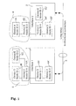
- Fig. 1 shows an IEEE 1394 network comprising a first sub network 5 and a second sub network 4 which are connected with each other by a long delay bi-directional connection 3.
- a first interface link layer device 1 is arranged which is allocated to and therefore regarded to belong to the first sub network 5, i. e. which behaves like a network device or node within the first sub network 5.
- a second interface link layer device 2 is connected in-between the second sub network 4 and the long delay bi-directional connection 3 which is allocated to and therefore regarded to belong to the second sub network 4.
- the first sub network 5 comprises 3 nodes, namely a first node 5A which is named device C and has a node ID 4, a second node 5B which is named device D and has a node ID 3, and a third node 5C which is named device E and has a node ID 2.
- the second sub network 4 comprises a fourth node 4A which is named device A and has a node ID 2 and a fifth node 4B which is named device B and has a node ID 3.
- each of the first interface link layer device 1 and the second interface link layer device 2 has the feature to transmit information about its own sub network 5, 4 to the respective other interface link layer device 2, 1, and based on information received from the respective other interface link layer device 2, 1 simulate the respective sub network 4, 5 the respective other interface link layer device 2, 1 is connected to.
- Such a simulation is performed by a respective interface link layer device 1, 2 according to the present invention at least during phases with severe timing requirements, such as the self ID phase during which each node of a sub network identifies itself to the sub network.
- the first interface link layer device 1 which is named interface 1 "comprises" the virtual fourth node 4A' which is a simulation of the fourth node 4A, namely of the device A, and the virtual fifth node 4B' which is a simultation of the node 4B, namely of the device B.
- the second interface link layer device 2 which is named interface 2 "comprises" the virtual first node 5A' which is a simulation of the first node 5A, namely of the device C, the virtual second node 5B' which is a simulation of the second node 5B, namely of the device D, and the virtual third node 5C' which is a simulation of the third node 5C, namely of the device E.
- the respective interface link layer device 1, 2 behaves like the number of nodes about which it received information so that new node identifiers are automatically assigned during a self ID phase to the virtual nodes according to the IEEE 1394 standard to secure that within each of the sub networks 5, 4 no conflicts occur. Therefore, within the first sub network 5, e. g. the node identifiers 2 to 4 are assigned to the physical nodes 5A to 5C and node identifiers different to 2 to 4 to the virtual fourth and fifth node 4A' and 4B' within the interface link layer device 1, in the shown example the node ID 0 for the virtual fourth node 4A' and the node ID 1 for the virtual fifth node 4B'.
- the node identifiers 2 and 3 are assigned to the physical fourth and fifth nodes 4A and 4B and node identifiers different thereto are assigned to the virtual first to third nodes 5A', 5B' and 5C' within the second interface link layer device 2, for example as shown in Fig. 1, the node ID 4 for the virtual first node 5A', the node ID 1 for the virtual second node B', and the node ID 0 for the virtual third node 5C'.
- the first sub network 5 and the second sub network 4 behave and act as independent networks respectively comprising the network devices and an interface link layer device which acts as a normal network device or network controller. Therefore, in the initial phase during which both interface link layer devices 1, 2 behave like a single node the first sub network 5 knows after a self ID phase that it comprises four nodes, namely the first to third nodes 5A to 5C and the first interface link layer device 1. Since this information is distributed within the whole first sub network 5 also the first interface link layer device 1 is able to collect the necessary information about the network topology of the first sub network 5. Similar, after the initial self ID phase of the second sub network 4 the interface link layer device 2 knows that the second sub network 4 comprises the fourth node 4A, the fifth node 4B, and the second interface link layer device 2.
- this information might comprise the number of nodes connected to a respective sub network and their name.
- the first interface link layer device 1 gets the information that the second sub network 4 comprises two network devices apart from the second interface link layer device 2, namely the fourth node 4A, i. e. the device A and the fifth node 4B, namely the device B
- the second interface link layer device 2 gets the information that the first sub network 5 comprises three devices apart from the first interface link layer device 1, namely the first node 5A, i. e. the device C, the second node 5B, namely the device D, and the third node 5C, namely the device E.
- both interface link layer devices 1, 2 should also know the whole network topology, i. e. the topology of each sub network 5, 4.
- each of the interface link layer devices 1, 2 according to the present invention initiates a second self ID phase within the own connected sub network, e. g. with a bus reset.
- the interface link layer device 1, 2 which received such information simulates a certain number of nodes according to the information received. Therefore, the first interface link layer device 1 simulates the second sub network, namely the fourth device 4A and the fifth device 4B, and the second interface link layer device 2 simulates the first sub network, namely the first to third nodes 5A to 5C.
- This simulation is performed strictly according to the IEEE 1394 standard, e. g.
- the first interface link layer device 1 sends two self ID packets to the first sub network 5 and represents two node IDs after the self ID phase.
- the second interface link layer device 2 sends three self ID packets and represents three node IDs after the self ID phase.
- the node identifiers within a sub network are newly assigned according to the IEEE 1394 standard. Therefore, to properly set-up a node ID translation table within each of the interface link layer devices 1, 2 an information about the new node IDs is exchanged in-between all connected interface link layer devices 1, 2.
- a bus reset to initiate a new self ID phase is always carried out in case a device is newly connected to an IEEE 1394 bus, removed therefrom or a device requests it. Therefore, based on this automatic self configuration mechanism defined within the IEEE 1394 standard, also the network set-up according to the present invention is always kept in a transparent self configured state, since an interface link layer device 1, 2 according to the present invention collects the information of the connected sub network 5, 4 in case of a not self initiated self ID phase and transmits it to another interface link layer device 2, 1 connected to the long delay link 3 which in turn initiates a new self ID phase within the respective own connected sub network as described above.
- an interface link layer device already comprises information about another sub network
- this information is also used during a not self initiated self ID phase to simulate this other sub network for the purpose of speeding up the whole self ID phase within the whole network.
- an interface link layer device receives an information from another interface link layer device which is not different to the information already received, no self initiated self ID phase is initiated by said interface link layer device.
- the node identifiers of the virtual nodes simulated within the interface link layer device according to the present invention are changed in respect to the nodes which are simulated the interface link layer device according to the present invention also translates the node IDs in packets that are sent to the other side of the long delay link 3 on basis of the node ID translation table which is set up after the second above-described self ID phase as described above.
- a respective interface link layer device 1, 2 preferably simulates not only the number of nodes within the respective other sub network 4, 5, but also the topology, i. e. the connection scheme of the respective nodes.
- the whole network is build up by physical and virtual nodes according to the same topology as if a normal link would be present instead of the interface link layer devices 1, 2 according to the present invention and the long delay link 3.
- This scheme is also shown in Fig. 1 in which the device C, i. e.
- the first node 5A builds the root of the first sub network 5 to which the devices D and E, namely the second and third nodes 5B and 5C, are respectively directly connected, and in which the device B, namely the fifth node 4B, builds the root of the second sub network 4 to which the device A, namely the fourth node 4A, is directly connected, and in which the link in-between said both sub networks 5, 4 is set up in-between both roots, i. e. in-between the first node 5A and the fifth node 4B.
- the number of nodes connected to the interface link layer devices is limited to 63, i. e. the whole network can have a maximum of 63 connected devices which each represent an own node.
- the long delay bi-directional connection 3 might have a delay larger than timeouts defined according to the IEEE 1394 standard, e. g. in the order of 100 ⁇ s ... 10 ms, since for larger delays asynchronous IEEE 1394 transactions may fail, because timing requirements are not met.
- this other interface link layer device can not only simulate the respective other sub network during the self ID phase to meet the timing requirements, but also during normal operation, e. g.
- the respective bus info block defining the capabilities of a device/node can be stored within the interface link layer device according to the present invention.
- the long delay link 3 through which the interface link layer devices according to the present invention communicate might be a coaxial cable, a wireless, an infra-red, an asynchronous transfer mode (ATM) which is used for professional long distance, high speed data connections, an unshielded twisted pair (UTP), a plastic optic fibre (POF) and/or another appropriate connection, e. g. a combination of the aforesaid types of connections.
- ATM asynchronous transfer mode
- UTP unshielded twisted pair
- POF plastic optic fibre
- the sub network on this side reconfigures itself by the standard IEEE 1394 mechanism and the new network topology information or further information required to properly simulate this sub network is transmitted to the other interface link layer device whereafter this other interface link layer device performs a new self ID phase within the connected sub network.
- interface link layer devices since the interface link layer devices according to the present invention only require an own node identifier during a self ID phase during which they do not simulate another sub network no node identifiers are "wasted" during operation, since in this case only node identifiers for the simulated devices are needed.
- the present invention is not limited to a network consisting of two sub networks, but can also comprise three or more sub networks connected to the same long delay bi-directional link 3.
- the communication on the long delay link 3 may be organized in packets or in channels as described in the above-referenced European Patent Application 99 126 221.3 and each interface link layer device simulates two or more sub networks.
- a distributed network including a long delay link can be built up compatible with existing IEEE1394 devices. These devices need not to know that a long delay connection exists when they communicate with a device simulated inside one of the interface link layer devices. Therefore, according to the present invention a distributed IEEE 1394 network including a long delay link is built up which is completely transparent and retaining all the advantages of the IEEE 1394 standard.
- the invention can also be applied to other communication standards to set-up long delay links while fulfilling timing requirements.
Landscapes
- Engineering & Computer Science (AREA)
- Computer Networks & Wireless Communication (AREA)
- Signal Processing (AREA)
- General Engineering & Computer Science (AREA)
- Theoretical Computer Science (AREA)
- Computer Hardware Design (AREA)
- Physics & Mathematics (AREA)
- General Physics & Mathematics (AREA)
- Computer Security & Cryptography (AREA)
- Small-Scale Networks (AREA)
- Computer And Data Communications (AREA)
- Information Transfer Systems (AREA)
Priority Applications (6)
| Application Number | Priority Date | Filing Date | Title |
|---|---|---|---|
| EP00104844A EP1133108A1 (de) | 2000-03-07 | 2000-03-07 | Vorrichtung einer Verbindungsschichtschnittstelle für grosse Verzögerungen |
| US09/799,748 US7454513B2 (en) | 2000-03-07 | 2001-03-06 | Interface link layer device for long delay connections |
| KR1020010011697A KR100867561B1 (ko) | 2000-03-07 | 2001-03-07 | 긴 지연 접속들을 위한 인터페이스 링크 층 디바이스 |
| JP2001063919A JP2001298466A (ja) | 2000-03-07 | 2001-03-07 | インターフェイスリンクレイヤ装置及びネットワーク設定方法 |
| US11/683,246 US20070153700A1 (en) | 2000-03-07 | 2007-03-07 | Interface link layer device for long delay connections |
| US11/683,832 US20070147387A1 (en) | 2000-03-07 | 2007-03-08 | Interface link layer device for long delay connections |
Applications Claiming Priority (1)
| Application Number | Priority Date | Filing Date | Title |
|---|---|---|---|
| EP00104844A EP1133108A1 (de) | 2000-03-07 | 2000-03-07 | Vorrichtung einer Verbindungsschichtschnittstelle für grosse Verzögerungen |
Publications (1)
| Publication Number | Publication Date |
|---|---|
| EP1133108A1 true EP1133108A1 (de) | 2001-09-12 |
Family
ID=8168046
Family Applications (1)
| Application Number | Title | Priority Date | Filing Date |
|---|---|---|---|
| EP00104844A Ceased EP1133108A1 (de) | 2000-03-07 | 2000-03-07 | Vorrichtung einer Verbindungsschichtschnittstelle für grosse Verzögerungen |
Country Status (4)
| Country | Link |
|---|---|
| US (3) | US7454513B2 (de) |
| EP (1) | EP1133108A1 (de) |
| JP (1) | JP2001298466A (de) |
| KR (1) | KR100867561B1 (de) |
Cited By (3)
| Publication number | Priority date | Publication date | Assignee | Title |
|---|---|---|---|---|
| EP1307005A1 (de) * | 2001-10-25 | 2003-05-02 | Sony International (Europe) GmbH | Programmierbare Verbindungsschicht-Schnittstelleneinrichtung |
| CN100361466C (zh) * | 2002-08-02 | 2008-01-09 | 德克萨斯仪器股份有限公司 | 数据通信系统暂停的自动恢复 |
| US7983888B2 (en) | 2004-03-19 | 2011-07-19 | Nxp B.V. | Simulation circuit of PCI express endpoint and downstream port for a PCI express switch |
Families Citing this family (6)
| Publication number | Priority date | Publication date | Assignee | Title |
|---|---|---|---|---|
| EP1198085B1 (de) * | 2000-10-10 | 2011-06-08 | Sony Deutschland GmbH | Zyklussynchronisierung zwischen miteinander verbundenen Teilnetzwerken |
| EP1199840A1 (de) * | 2000-10-19 | 2002-04-24 | THOMSON multimedia | Verfahren zum drahtlosen Anschluss einer entfernten IEEE1394-Vorrichtung zu einer Gruppe von IEEE1394-Vorrichtungen |
| US8762568B1 (en) * | 2001-07-06 | 2014-06-24 | Cisco Technology, Inc. | Method and apparatus for inter-zone restoration |
| JP3683227B2 (ja) * | 2002-03-28 | 2005-08-17 | 日本電気エンジニアリング株式会社 | ローカルバスブリッジ |
| US7539967B1 (en) * | 2006-05-05 | 2009-05-26 | Altera Corporation | Self-configuring components on a device |
| US9148342B2 (en) * | 2009-10-07 | 2015-09-29 | Nec Corporation | Information system, control server, virtual network management method, and program |
Citations (5)
| Publication number | Priority date | Publication date | Assignee | Title |
|---|---|---|---|---|
| EP0837579A2 (de) * | 1996-10-15 | 1998-04-22 | Kabushiki Kaisha Toshiba | Gerät zur Datenübertragungssteuerung, Relaisvorrichtung und Steuerungsvorrichtung für ein Haus-Netzwerk |
| EP0841791A1 (de) * | 1996-04-04 | 1998-05-13 | Sony Corporation | Übertragungssteuerung und verfahren zur steuerung der übertragung |
| DE19835668A1 (de) * | 1997-08-07 | 1999-02-25 | Matsushita Electric Industrial Co Ltd | Übertragungsmedienverbindungsvorrichtung, steuernde Vorrichtung, gesteuerte Vorrichtung und Speichermedium |
| EP0933900A2 (de) * | 1998-01-29 | 1999-08-04 | Nec Corporation | Brücke für den IEEE 1394 Bus |
| US6016388A (en) * | 1994-06-08 | 2000-01-18 | Hughes Electronics Corporation | Method and apparatus for requesting and retrieving information from a source computer using terrestrial and satellite interfaces |
Family Cites Families (18)
| Publication number | Priority date | Publication date | Assignee | Title |
|---|---|---|---|---|
| US5157972A (en) * | 1991-03-29 | 1992-10-27 | Rosemount Inc. | Pressure sensor with high modules support |
| US6701370B1 (en) * | 1994-06-08 | 2004-03-02 | Hughes Electronics Corporation | Network system with TCP/IP protocol spoofing |
| US5537533A (en) * | 1994-08-11 | 1996-07-16 | Miralink Corporation | System and method for remote mirroring of digital data from a primary network server to a remote network server |
| JP3572768B2 (ja) * | 1995-08-12 | 2004-10-06 | ソニー株式会社 | データ通信方法 |
| US5940596A (en) * | 1996-03-25 | 1999-08-17 | I-Cube, Inc. | Clustered address caching system for a network switch |
| JPH09282263A (ja) * | 1996-04-12 | 1997-10-31 | Sony Corp | 電子機器及びその識別情報構成方法 |
| WO1998004068A1 (fr) * | 1996-07-19 | 1998-01-29 | Sony Corporation | Procede de transmission de donnees numeriques et appareil correspondant |
| JPH10174073A (ja) | 1996-12-11 | 1998-06-26 | Sony Corp | 伝送装置および伝送方法 |
| US6073194A (en) * | 1997-07-31 | 2000-06-06 | Advanced Micro Devices, Inc. | Transaction based windowing methodology for pre-silicon verification |
| US6157972A (en) * | 1997-12-05 | 2000-12-05 | Texas Instruments Incorporated | Apparatus and method for processing packetized information over a serial bus |
| US6678769B1 (en) * | 1998-02-24 | 2004-01-13 | Canon Kabushiki Kaisha | Control apparatus and method for managing a logical connection between source and destination nodes |
| KR100272108B1 (ko) * | 1998-10-13 | 2000-11-15 | 윤종용 | Ieee 1394 가상 네트웍 생성방법 및 그 콘트롤러 |
| US6327637B1 (en) * | 1998-12-18 | 2001-12-04 | Cirrus Logic, Inc. | Interface tap for 1394-enabled serial bus device |
| JP2000209220A (ja) * | 1999-01-14 | 2000-07-28 | Toshiba Corp | コンピュ―タ、ネットワ―ク制御装置、およびこれらを用いたシステム並びにリモ―ト起動方法 |
| DE69940781D1 (de) * | 1999-12-30 | 2009-06-04 | Sony Deutschland Gmbh | Schnittstellenverbindungsschicht- Einrichtung zum Aufbau eines verteilten Netzwerks |
| US6414971B1 (en) * | 2000-01-31 | 2002-07-02 | Sony Corporation | System and method for delivering data packets in an electronic interconnect |
| EP1198085B1 (de) * | 2000-10-10 | 2011-06-08 | Sony Deutschland GmbH | Zyklussynchronisierung zwischen miteinander verbundenen Teilnetzwerken |
| US6710370B2 (en) * | 2002-01-07 | 2004-03-23 | Xerox Corporation | Image sensor with performance enhancing structures |
-
2000
- 2000-03-07 EP EP00104844A patent/EP1133108A1/de not_active Ceased
-
2001
- 2001-03-06 US US09/799,748 patent/US7454513B2/en not_active Expired - Fee Related
- 2001-03-07 KR KR1020010011697A patent/KR100867561B1/ko not_active Expired - Fee Related
- 2001-03-07 JP JP2001063919A patent/JP2001298466A/ja not_active Withdrawn
-
2007
- 2007-03-07 US US11/683,246 patent/US20070153700A1/en not_active Abandoned
- 2007-03-08 US US11/683,832 patent/US20070147387A1/en not_active Abandoned
Patent Citations (5)
| Publication number | Priority date | Publication date | Assignee | Title |
|---|---|---|---|---|
| US6016388A (en) * | 1994-06-08 | 2000-01-18 | Hughes Electronics Corporation | Method and apparatus for requesting and retrieving information from a source computer using terrestrial and satellite interfaces |
| EP0841791A1 (de) * | 1996-04-04 | 1998-05-13 | Sony Corporation | Übertragungssteuerung und verfahren zur steuerung der übertragung |
| EP0837579A2 (de) * | 1996-10-15 | 1998-04-22 | Kabushiki Kaisha Toshiba | Gerät zur Datenübertragungssteuerung, Relaisvorrichtung und Steuerungsvorrichtung für ein Haus-Netzwerk |
| DE19835668A1 (de) * | 1997-08-07 | 1999-02-25 | Matsushita Electric Industrial Co Ltd | Übertragungsmedienverbindungsvorrichtung, steuernde Vorrichtung, gesteuerte Vorrichtung und Speichermedium |
| EP0933900A2 (de) * | 1998-01-29 | 1999-08-04 | Nec Corporation | Brücke für den IEEE 1394 Bus |
Non-Patent Citations (1)
| Title |
|---|
| MANDEVILLE R: "WHO'S FOOLING WHO? ÖFINDING ISDN ROUTERS THAT CAN REALLY SPOOF LAN TRAFFIC", November 1994, DATA COMMUNICATIONS,US,MCGRAW HILL. NEW YORK, VOL. 23, NR. 16, PAGE(S) 88-92,94,96, ISSN: 0363-6399, XP000471525 * |
Cited By (4)
| Publication number | Priority date | Publication date | Assignee | Title |
|---|---|---|---|---|
| EP1307005A1 (de) * | 2001-10-25 | 2003-05-02 | Sony International (Europe) GmbH | Programmierbare Verbindungsschicht-Schnittstelleneinrichtung |
| US7124227B2 (en) | 2001-10-25 | 2006-10-17 | Sony International (Europe) Gmbh | Programmable interface link layer device |
| CN100361466C (zh) * | 2002-08-02 | 2008-01-09 | 德克萨斯仪器股份有限公司 | 数据通信系统暂停的自动恢复 |
| US7983888B2 (en) | 2004-03-19 | 2011-07-19 | Nxp B.V. | Simulation circuit of PCI express endpoint and downstream port for a PCI express switch |
Also Published As
| Publication number | Publication date |
|---|---|
| US7454513B2 (en) | 2008-11-18 |
| KR20010088437A (ko) | 2001-09-26 |
| US20070153700A1 (en) | 2007-07-05 |
| US20010023452A1 (en) | 2001-09-20 |
| KR100867561B1 (ko) | 2008-11-10 |
| JP2001298466A (ja) | 2001-10-26 |
| US20070147387A1 (en) | 2007-06-28 |
Similar Documents
| Publication | Publication Date | Title |
|---|---|---|
| US20070153700A1 (en) | Interface link layer device for long delay connections | |
| US6445711B1 (en) | Method of and apparatus for implementing and sending an asynchronous control mechanism packet used to control bridge devices within a network of IEEE STD 1394 serial buses | |
| JP2510606B2 (ja) | ロ−カル エリア デ−タ ディストリビユ−ション システム | |
| US5784648A (en) | Token style arbitration on a serial bus by passing an unrequested bus grand signal and returning the token by a token refusal signal | |
| US5289579A (en) | Channel adapter for broadband communications at channel speeds | |
| US8379654B2 (en) | Method of and apparatus for providing isochronous services over switched ethernet including a home network wall plate having a combined IEEE 1394 and ethernet modified hub | |
| CN115996204B (zh) | 带外以太网接口交换装置、多节点服务器系统及服务器设备 | |
| US5621726A (en) | Point-to-point communication network and method and adapter for virtualizing a LAN system | |
| EP2047370A1 (de) | Verfahren und vorrichtung zum verteilen von usb-hub-funktionen über ein netzwerk | |
| CN106713096B (zh) | 总线型fc-ae-1553网络系统及网络终端之间的数据发送和获取方法 | |
| JP4467804B2 (ja) | ワイヤレス型コネクションを含む通信ネットワークにおける帯域幅管理方法 | |
| US8359401B2 (en) | Network switch | |
| US6738843B2 (en) | Method and system for generating multiple self-ID packets on the 1394 bus using a standard PHY chip | |
| US20110176549A1 (en) | Method of bus configuration to enable device bridging over dissimilar buses | |
| US7124227B2 (en) | Programmable interface link layer device | |
| EP0505781B1 (de) | Serieller Multimedia Linienschalter für Parallelnetzwerke und ein heterogenes homologes Rechnersystem | |
| Iskefiyeli et al. | Interconnection of autonomous profibus segments through ieee 802.16 wman | |
| JP2715137B2 (ja) | 通信網制御方式 | |
| KR100577147B1 (ko) | 버스시스템의기기제어방법 | |
| Sastry et al. | An Open Specification for Fire wire Standard to Extend its suitability to diversified Applications | |
| Mokhoff | Data communications: Local data nets: Untying the office knot: Establishing standards for accessing local data networks may facilitate intra-office communications | |
| JPS6162958A (ja) | 通信ネツトワ−ク制御方式 | |
| JP2000059407A (ja) | ネットワ―ク管理方泡情報処理方法及び装置、情報提供媒体 | |
| CA2356330A1 (en) | System for tracing data channels through a channel-based network | |
| JPH04280529A (ja) | データ通信方式 |
Legal Events
| Date | Code | Title | Description |
|---|---|---|---|
| PUAI | Public reference made under article 153(3) epc to a published international application that has entered the european phase |
Free format text: ORIGINAL CODE: 0009012 |
|
| AK | Designated contracting states |
Kind code of ref document: A1 Designated state(s): DE FR GB Kind code of ref document: A1 Designated state(s): AT BE CH CY DE DK ES FI FR GB GR IE IT LI LU MC NL PT SE |
|
| AX | Request for extension of the european patent |
Free format text: AL;LT;LV;MK;RO;SI |
|
| 17P | Request for examination filed |
Effective date: 20020213 |
|
| AKX | Designation fees paid |
Free format text: DE FR GB |
|
| RAP1 | Party data changed (applicant data changed or rights of an application transferred) |
Owner name: SONY DEUTSCHLAND GMBH |
|
| 17Q | First examination report despatched |
Effective date: 20061122 |
|
| RAP1 | Party data changed (applicant data changed or rights of an application transferred) |
Owner name: SONY DEUTSCHLAND GMBH |
|
| STAA | Information on the status of an ep patent application or granted ep patent |
Free format text: STATUS: THE APPLICATION HAS BEEN REFUSED |
|
| 18R | Application refused |
Effective date: 20100312 |