EP1133111A2 - Verfahren und Vorrichtung zur Verwaltung von Servicequalität in Netzwerkeinheiten - Google Patents
Verfahren und Vorrichtung zur Verwaltung von Servicequalität in Netzwerkeinheiten Download PDFInfo
- Publication number
- EP1133111A2 EP1133111A2 EP01104298A EP01104298A EP1133111A2 EP 1133111 A2 EP1133111 A2 EP 1133111A2 EP 01104298 A EP01104298 A EP 01104298A EP 01104298 A EP01104298 A EP 01104298A EP 1133111 A2 EP1133111 A2 EP 1133111A2
- Authority
- EP
- European Patent Office
- Prior art keywords
- information
- qos
- network device
- data
- data packet
- Prior art date
- Legal status (The legal status is an assumption and is not a legal conclusion. Google has not performed a legal analysis and makes no representation as to the accuracy of the status listed.)
- Granted
Links
- 238000000034 method Methods 0.000 title claims description 17
- 230000005540 biological transmission Effects 0.000 claims abstract description 38
- 238000004891 communication Methods 0.000 claims description 10
- 230000008859 change Effects 0.000 claims description 9
- 230000004044 response Effects 0.000 claims description 7
- 238000012544 monitoring process Methods 0.000 claims description 4
- 238000010348 incorporation Methods 0.000 claims 1
- 230000000717 retained effect Effects 0.000 claims 1
- 238000013461 design Methods 0.000 abstract description 3
- 238000012545 processing Methods 0.000 description 49
- 230000009471 action Effects 0.000 description 37
- 238000012360 testing method Methods 0.000 description 19
- 230000000875 corresponding effect Effects 0.000 description 7
- 230000006870 function Effects 0.000 description 7
- 238000013459 approach Methods 0.000 description 6
- 238000010586 diagram Methods 0.000 description 4
- 230000000694 effects Effects 0.000 description 4
- 238000013507 mapping Methods 0.000 description 4
- 230000008569 process Effects 0.000 description 4
- 238000012423 maintenance Methods 0.000 description 3
- 238000007726 management method Methods 0.000 description 3
- 230000007246 mechanism Effects 0.000 description 3
- 230000002085 persistent effect Effects 0.000 description 3
- 239000000872 buffer Substances 0.000 description 2
- 230000001934 delay Effects 0.000 description 2
- 230000003111 delayed effect Effects 0.000 description 2
- 239000000284 extract Substances 0.000 description 2
- 239000012634 fragment Substances 0.000 description 2
- 241000282412 Homo Species 0.000 description 1
- 230000003213 activating effect Effects 0.000 description 1
- 230000002411 adverse Effects 0.000 description 1
- 238000005267 amalgamation Methods 0.000 description 1
- 230000006399 behavior Effects 0.000 description 1
- 230000003139 buffering effect Effects 0.000 description 1
- 230000015556 catabolic process Effects 0.000 description 1
- 238000006731 degradation reaction Methods 0.000 description 1
- 238000011161 development Methods 0.000 description 1
- 238000005538 encapsulation Methods 0.000 description 1
- 238000005516 engineering process Methods 0.000 description 1
- 239000012464 large buffer Substances 0.000 description 1
- 238000012986 modification Methods 0.000 description 1
- 230000004048 modification Effects 0.000 description 1
- 230000006855 networking Effects 0.000 description 1
- 230000011664 signaling Effects 0.000 description 1
- 230000001360 synchronised effect Effects 0.000 description 1
Images


Classifications
-
- H—ELECTRICITY
- H04—ELECTRIC COMMUNICATION TECHNIQUE
- H04L—TRANSMISSION OF DIGITAL INFORMATION, e.g. TELEGRAPHIC COMMUNICATION
- H04L47/00—Traffic control in data switching networks
- H04L47/10—Flow control; Congestion control
-
- H—ELECTRICITY
- H04—ELECTRIC COMMUNICATION TECHNIQUE
- H04L—TRANSMISSION OF DIGITAL INFORMATION, e.g. TELEGRAPHIC COMMUNICATION
- H04L41/00—Arrangements for maintenance, administration or management of data switching networks, e.g. of packet switching networks
- H04L41/08—Configuration management of networks or network elements
- H04L41/0803—Configuration setting
- H04L41/0813—Configuration setting characterised by the conditions triggering a change of settings
- H04L41/082—Configuration setting characterised by the conditions triggering a change of settings the condition being updates or upgrades of network functionality
-
- H—ELECTRICITY
- H04—ELECTRIC COMMUNICATION TECHNIQUE
- H04L—TRANSMISSION OF DIGITAL INFORMATION, e.g. TELEGRAPHIC COMMUNICATION
- H04L45/00—Routing or path finding of packets in data switching networks
- H04L45/302—Route determination based on requested QoS
-
- H—ELECTRICITY
- H04—ELECTRIC COMMUNICATION TECHNIQUE
- H04L—TRANSMISSION OF DIGITAL INFORMATION, e.g. TELEGRAPHIC COMMUNICATION
- H04L45/00—Routing or path finding of packets in data switching networks
- H04L45/302—Route determination based on requested QoS
- H04L45/306—Route determination based on the nature of the carried application
-
- H—ELECTRICITY
- H04—ELECTRIC COMMUNICATION TECHNIQUE
- H04L—TRANSMISSION OF DIGITAL INFORMATION, e.g. TELEGRAPHIC COMMUNICATION
- H04L45/00—Routing or path finding of packets in data switching networks
- H04L45/60—Router architectures
-
- H—ELECTRICITY
- H04—ELECTRIC COMMUNICATION TECHNIQUE
- H04L—TRANSMISSION OF DIGITAL INFORMATION, e.g. TELEGRAPHIC COMMUNICATION
- H04L47/00—Traffic control in data switching networks
- H04L47/10—Flow control; Congestion control
- H04L47/24—Traffic characterised by specific attributes, e.g. priority or QoS
- H04L47/2425—Traffic characterised by specific attributes, e.g. priority or QoS for supporting services specification, e.g. SLA
-
- H—ELECTRICITY
- H04—ELECTRIC COMMUNICATION TECHNIQUE
- H04L—TRANSMISSION OF DIGITAL INFORMATION, e.g. TELEGRAPHIC COMMUNICATION
- H04L47/00—Traffic control in data switching networks
- H04L47/70—Admission control; Resource allocation
- H04L47/76—Admission control; Resource allocation using dynamic resource allocation, e.g. in-call renegotiation requested by the user or requested by the network in response to changing network conditions
- H04L47/762—Admission control; Resource allocation using dynamic resource allocation, e.g. in-call renegotiation requested by the user or requested by the network in response to changing network conditions triggered by the network
-
- H—ELECTRICITY
- H04—ELECTRIC COMMUNICATION TECHNIQUE
- H04L—TRANSMISSION OF DIGITAL INFORMATION, e.g. TELEGRAPHIC COMMUNICATION
- H04L47/00—Traffic control in data switching networks
- H04L47/70—Admission control; Resource allocation
- H04L47/80—Actions related to the user profile or the type of traffic
- H04L47/805—QOS or priority aware
-
- H—ELECTRICITY
- H04—ELECTRIC COMMUNICATION TECHNIQUE
- H04L—TRANSMISSION OF DIGITAL INFORMATION, e.g. TELEGRAPHIC COMMUNICATION
- H04L41/00—Arrangements for maintenance, administration or management of data switching networks, e.g. of packet switching networks
- H04L41/50—Network service management, e.g. ensuring proper service fulfilment according to agreements
- H04L41/5003—Managing SLA; Interaction between SLA and QoS
Definitions
- the present invention relates to telecommunication networking in general, and in particular to network devices as they pertain to service levels for data delivery. More specifically, the present invention relates to the real-time adjustment of quality-related attributes in network devices.
- Router and switch devices are used for connecting networks (e.g., LANs, WANs, and the like) and for transferring datagrams from one network to another.
- Datagrams contain communication data (payload) as well as a source address and a final destination address.
- a widely used datagram format is the transmission control protocol/internet protocol (TCP/IP) format.
- TCP/IP transmission control protocol/internet protocol
- a switch simply provides routing of incoming datagrams to a specific output port based on the destination information contained in the datagram.
- a router likewise, will send a datagram to an intermediate destination which ultimately results in the final destination. The router, however, will select from among many intermediate destinations depending on criteria such as traffic conditions, availability, and the like.
- Hosts coupled in a network carry a variety of kinds of data. Certain types of data transmissions (or data flows) may require a certain level of quality from the network.
- a common attribute is Quality of Service (QoS).
- QoS Quality of Service
- the transmission of video data and/or voice data typically requires a higher QoS than is typically needed when transferring data to display a World Wide Web (WWW) page in order to ensure a smooth presentation of the video and/or voice content.
- WWW World Wide Web
- This especially the case for audio content because human hearing is very sensitive to degradations in audio transmissions, even as compared to video transmissions.
- delays in displaying the page contents resulting from a lower QoS can be tolerated.
- QoS can manifest itself in various ways. For example, QoS may specify a minimum bandwidth requirement, a maximum transmission delay, or an amount of memory or buffer space required for the data flow. Thus, a video conference or other real-time data transmission may have a high QoS, requiring substantial bandwidth and minimum delay from the network. By specifying the QoS required for a particular data flow, the data source or destination can ascertain whether an acceptable path is available. Thus, QoS routing allows data flows to be routed around links that lack the necessary resources.
- IP Internet protocol
- network devices In a typical operating environment of an Internet protocol (IP) router or switch (collectively referred to herein as network devices), there is a system administrator who will adjust the QoS setting in the course of performing various administrative tasks.
- IP Internet protocol
- an automated administration-type controller responsible for managing a set of network devices might periodically adjust the QoS settings in response to traffic conditions within the domain serviced by the network devices.
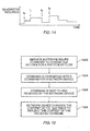
- the flowchart shown in Fig. 15 highlights the steps of a conventional approach to changing the QoS setting in a network device.
- the administrator whether a human or an automated controller, typically gains access to the network device via a maintenance channel.
- This can be a logical channel such as a telnet session accessed over one of the local area network (LAN) interfaces on the network device, e.g., an ethernet port.
- the network device might have a serial port or the like having a connection to a PC.
- an administration command to change the QoS setting is submitted, step 1504.
- the administration command is communicated to an internal controller of the network device, step 1506, by way of a suitable protocol standard, command interface, or application program interface (API).
- a management/maintenance protocol such as SNMP (Simple Network Management Protocol) is most common.
- SNMP Simple Network Management Protocol
- a controller computer within the network device extracts QoS parameters from the command and updates the contents of a QoS table, step 1508. Typically, this sequence is executed rather infrequently, on the order of once every few hours or longer.
- the QoS control would not be applied just in a "session-oriented" time granularity as mentioned above, but rather in "real-time” granularity.
- the destination site might be able to compensate by the use of additional software that receives the packets and buffers them.
- the software can then re-sequence the packets and display the image properly.
- the receiving software can implement a very large buffer to store the entire image before displaying it.
- the additional complexity in the client-side software is undesirable and degrades performance.
- the latter solution further suffers from the requirement of additional memory, either real or virtual (which would further degrade performance from to the likelihood of additional delay due to increased disk swapping).
- buffering may not work altogether because of the large amounts of data in a live video feed and the real time aspects of live action video. In such situations, data packets arriving out of sequence might be discarded, resulting in a garbled video image.
- Typical schemes for adjusting the QoS of a network device are known.
- the "differentiated services" architecture defined by the Internet Engineering Task Force (IETF) uses an IP-layer packet marking scheme to convey a desired QoS.
- the IP header contains a differentiated services code point (DSCP) field.
- DSCP differentiated services code point
- the DSCP is used to map each packet to a particular transmission priority in the network device.
- the mapping between the DSCP value and the transmission priority typically is set by the network management system prior to the start of a transmission. The mapping remains unchanged until the transmission is complete. In this scheme, there is no mechanism for changing the mapping during a transmission.
- an “active networks” users can insert customized programs into the data stream.
- the packet of data contains a program that is executed by one or more network devices encountered along its journey to the destination.
- a program can be written and inserted into the data stream to control the QoS behavior at the network nodes.
- a disadvantage with this approach is that the encapsulation of the program into the packet limits the amount of payload the packet can carry.
- the versatility and flexibility of active networks provide fine control over the QoS on a packet-by-packet basis, this capability occurs at the cost of having to provide software execution at each network device. The extra processing can degrade the performance of network transmissions.
- the resources of a network are represented as software abstractions.
- the software interacts with the network devices through means of a set of standardized application program interfaces (API's).
- API's application program interfaces
- the present invention allows a data service provider to communicate information to one or more network devices so to alter at least one transmission attribute in the network device during the normal course of data transmissions to its clients.
- the data service provider is then able to tailor appropriate service levels for its various clients by more effectively allocating network resource.
- the data service provider can effectively react to changing traffic conditions by reallocating resources among all of its clients. Additional services and more flexible billing policies can be developed.
- a data delivery system includes a data server in data communication with one or more network devices. Accordingly, there is the transmission of first information to a targeted network device, a current network device attribute of which is to be changed.
- the transmission of first information originates from the data server.
- the first information comprises at least one new network device attribute, which is stored in the network device.
- a transmission of second information to the target network device is subsequently produced by the data server.
- the second information acts as a trigger, activating the network device to update its current attribute setting with the new attribute setting. Therefore, dynamic real-time adjustments to the network device attribute becomes feasible.
- the first information may also contain addressing information to identify the targeted network device(s).
- the second information can be contained in a client-destined data packet.
- the new attribute setting in the targeted network device is put into effect prior to sending the data packet containing the second information which triggers the new attribute setting activity.
- the activity occurs subsequent to transmission of the data packet containing the second information.
- either or both the first and second information can be contained in special data packets that are intercepted by the network device.
- the network device attribute being adjsuted is a quality of service (QoS) setting
- the first information contains QoS parameters which specify a QoS setting.
- the first information contains a list of QoS parameters.
- a list of QoS parameters is built up in the targeted network device, and the second information contains an index into the list of QoS parameters.
- a network device in yet another aspect of the invention, includes network circuitry coupled to a network for receiving data packets from the network. There is data monitoring circuitry to detect the presence of a received data packet containing first information.
- a first program code is provided to receive one or more externally provided QoS parameters.
- a second program code is provided to alter the QoS setting of the network device in accordance with the externally provided QoS parameters in response to detecting the first information.
- Fig. 1 is a simplified system diagram of a typical data server application over a network which operates in accordance with the present invention.
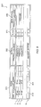
- Fig. 2 is a simplified block diagram of a router configured in accordance with the present invention.
- Fig. 3 illustrates a flow control table in accordance with one embodiment of the invention.
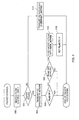
- Fig. 4 outlines some of the processing which takes place in a forwarding controller in accordance with an embodiment of the invention.
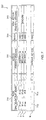
- Fig. 5 outlines a variation in the processing of the forwarding controller.
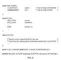
- Fig. 6 is an API highlighting the features for setting the flow control table in accordance with the present invention.
- Fig. 7 illustrates a flow control table in accordance with another embodiment of the invention.
- Fig. 8 outlines some of the processing which takes place in a forwarding controller in accordance with another embodiment of the invention.
- Fig. 9 outlines a variation in the processing of the forwarding controller.
- Figs. 10 - 12 are variations of API's highlighting the features for setting the flow control table of Fig. 7
- Fig. 13 illustrates yet another embodiment of the flow control table.
- Fig. 14 shows a typical bandwidth pattern in a video stream.
- Fig. 15 illustrates a typical prior art maintenance sequence.
- an embodiment of the invention provides for a network service deployed over a programmable network.
- the network service is provided in accordance with the Multi-Quality Layered Video Service (MQLVS) model for delivering video data, as discussed in a paper presented by T. Suzuki at the Meeting of Study Group 16 during the International Telecommunication Union on May 1999, entitled “Scalable MPEG-2 Video Transmission System over IP Network,” and incorporated herein in full for all purposes.
- MQLVS Multi-Quality Layered Video Service
- Fig. 1 is a simplified system diagram of one such programmable network.
- a video server 100 transmits a video program over a network 10 to various clients 104.
- the network 10 comprises the Internet which is a global amalgamation of networks and network device. Alternatively, network 10 can be a more localized intranet.
- the network is defined by the interconnection of a multitude of network devices 102, including routing devices and switching devices.
- clients 104 At the receiving end of video server 100 are clients 104.
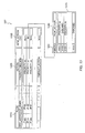
- Fig. 2 is a simplified system diagram illustrating the typical configuration of a router device 102.
- the router device includes a controller portion 210 which is typically a computer residing separately from a router portion 220, typically a conventional router.
- controller portion 210 is located next to router portion 220.
- the controller 210 can be a PC or a work station coupled to router portion 220 by a network link.
- the controller 210 is located remotely.
- a single controller is used to manage one or more router portions 220.
- the controller portion 210 includes service software 212 which executes on top of an application program interface (API) 214.
- the API provides an interface between service software 212 and controller software 216.
- the controller software communicates directly with router portion 220.
- the service software provides network services in accordance with the MQLVS model for delivering video content.
- the router portion 220 includes one or more network interface circuits 222 (e.g., Ethernet interfaces) coupled to the network 10. Data packets are received and transmitted over the networks by the network interface circuits.
- the network interface circuits 222 are coupled to an internal bus or switch 224 by way of forwarding controllers 226. Each forwarding controller 226 includes a forwarding control table 227.
- a router typically comprises multiple output queues for a single physical port.
- Each queue can be set with different quality of service attributes, collectively referred to as QoS parameters.
- QoS parameters For example, each queue can have a different precedence for sending a data packet placed in the queue.
- Each queue can also have a different packet discard level.
- the forwarding control tables 227 contain information (the QoS parameters) which establish the QoS settings of each output queue for the transmission of incoming data packets.
- a router control 228 maintains the forwarding control tables 227.
- a commonly used video platform for transmission over the network is the standard defined by the Motion Picture Experts Group (MPEG).
- MPEG Motion Picture Experts Group
- the video data can be blocked in a data unit comprising an I-frame data packet, followed by groups of B-frame data packets.
- Each group of B-frame data packets has an associated P-frame data packet which, among other things, serves to separate one group of B-frames from the next.
- Decoding of a P-frame requires information contained in the I-frame.
- Decoding of a B-frame uses information contained in both the I-frame and its corresponding P-frame.
- Each client 104 can decide on a particular level of video quality.
- a higher quality video consumes more bandwidth. Consequently, the client who requires or prefers high quality video can be charged a premium for the increased level of service. Most consumers are satisfied with a normal, but lower quality video and thus would be charged less for the service.
- the varying bandwidth requirements are shown in Fig. 1 by the differently sized data flow arrows. It is possible that a change in quality may need to be effectuated for all clients as a result of adverse network traffic conditions.
- This service-changing capability is realized by selective packet transmission processing contained in each of the router devices 102.
- the content of the packets is recognized as being I-frame data, P-frame data, or B-frame data.
- the flow control table 227 can be set to discard all the packets not needed to attain the desired quality level. Consequently, only those packets needed to achieve the desired quality will be forwarded.
- the quality level is set in the router prior to transmitting the video. If the quality level is changed during the transmission, the router will alter its packet selection processing accordingly. However, this means that certain packets may suddenly no longer be transmitted to some clients, or conversely some clients will begin receiving packets unexpectedly. In the case of MPEG data packets, for example, this could mean that a client might not receive a P-frame packet. As a consequence, the client would not be able to correctly decode a subsequently received B-frame packet. To avoid this situation, conventional routers change settings only at the beginning of data unit, namely, when the router receives an I-frame packet.
- FIG. 3 illustrates an embodiment of a flow control table 227.
- the flow control table includes entries 1, 2, 3,... N. Each entry comprises a FLOW field 310, an ACTION field 320, a FLAG field 330, and a NEW_ACTION field 340.
- the FLOW field 310 further comprises a source address sub-field 312 and a corresponding destination address sub-field 314.
- a flow can be identified by ⁇ SRC_ADDR, DST_ADDR, SRC_PORT, DST_PORT, PROTOCOL ⁇ .
- the ports are software entities assigned by the protocol (e.g., TCP/IP,
- UDP/IP User Datagram Protocol
- server & client The FLOW field is matched against the information contained in the header field of an incoming packet, identifying which flow the incoming packet belongs to.
- the ACTION and NEW_ACTION fields contain QoS parameters which determine the output QoS for an outgoing data packet, as will be explained below.
- the mapping between TOS value (or DSCP value) and the output queue are examples of QoS parameters.
- the TOS (or DSCP) value can be added in FLOW field 310.
- the QoS parameter would be just the Queue ID.
- the output queues are pre-configured with certain priority/discard settings, and assigning a particular packet to a queue means directly giving a particular (predetermined) QoS to the packet.
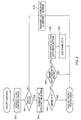
- Fig. 4 outlines the processing of a forwarding controller 226. Processing begins by the arrival of a data packet over network 10.
- the network interface 222 receives the packet and delivers it to forwarding controller 226.
- the forwarding controller inspects the header of the data packet to find a matching entry in flow control table 227, step 402. It is contemplated that a "key" can be embedded in the payload, and a search be done against this information. In this case, the FLOW field would not simply contain information about a "flow" from point A to B, but rather information based on the content/semantics of the data itself.
- step 402 matches the source address contained in the received data packet against the source address sub-field 312 of the FLOW field 310 of each entry in the flow control table, and matching a destination address also contained the received data packet against the destination address sub-field 314 of the FLOW field 310 in each entry of the flow control table.
- additional subfields in Flow field 310 would similarly be matched.
- the FLOW field is used as a "key" to match information contained in the header field of the incoming packet. That is to say, for each incoming packet, a search through the flow control table is done, and when matching entry is found in the FLOW field, corresponding ACTION is taken.
- a wildcard specification may be possible. For example, an entry “xx.yy.zz. * " in SRC_ADDR can match IP address "xx.yy.zz.1", “xx.yy.zz.3”, and so on.
- the wildcard itself may be realized by introducing “mask” fields. For instance, SRC_ADDR_MASK of value "255.255.255.0” would give the same matching result as wildcard format.
- a test is made to determine if an entry for the received data packet was found, step 401. If no entry was found, then a DEFAULT ACTION is taken, step 410, in connection with how the data packet is to be forwarded. For example, the default action might simply be to dump the packet, without forwarding it. Processing of the received data packet is then concluded.
- a matching entry is found if both the source and destination address sub-fields of its FLOW field 310 matches the source and destination fields contained in the received data packet. If a matching entry is found, processing proceeds to a second test at step 403. Here, the FLAG field 330 of the matching entry is inspected. If the FLAG field 330 is not set (e.g., contains a value of '0'), then processing proceeds to step 404. At step 404, the received data packet is transmitted from the router 102 (i.e. forwarded). The output QoS of the transmitted data packet is determined by the parameters contained in the ACTION field 320 of the matching entry. Processing of the data packet then concludes.
- processing proceeds to yet another test at step 405.
- information contained in a predetermined portion of the data packet is tested.
- a specific field (bit) in the IP packet header is used; for example, the UNUSED bits in the TOS field of the IP (v4) header, or the IP OPTIONS field of the IP header.
- the predetermined portion of the data packet preferably is a single bit that is either set (e.g., contains a '1') or not set (e.g., contains a '0'). If the predetermined portion is not set, then processing proceeds according to step 404. That is, the data packet is transmitted with an output QoS determined by the QoS parameters contained in the ACTION field 320 of the matching entry. Processing of the packet is then concluded.
- step 406 the information contained in the NEW_ACTION field 340 of the matching entry is copied to the ACTION field 320 of that entry. Detecting the presence of the information in the predetermined portion of the data packet triggers the copying of the contents in the NEW_ACTION field to the ACTION field. By so doing, this changes the output QoS of the associated queue for subsequent transmissions through that queue.
- the FLAG field 330 of the matching entry is cleared (e.g., set to '0'), step 408.
- the data packet is then transmitted in step 404, as before, with an output QoS determined by the QoS parameters contained in the ACTION field 320 of the matching entry. However, the parameters contained in the ACTION field now are those obtained from the NEW_ACTION field 340. Thus, the data packet will be transmitted in step 404 with a new QoS setting. Processing of the received data packet is then concluded.
- Fig. 5 shows the process flow in the forwarding controller 226 in a variation of the first embodiment of the invention.
- processing begins by the arrival of a data packet over network 10 via network interface 222.
- the forwarding controller 226 inspects the contents of the data packet to find a matching entry in flow control table 227, step 502.
- the source address contained in the received data packet is matched against the source address sub-field 312 of the FLOW field 310 of each entry in the flow control table.
- a destination address also contained the received data packet likewise is matched against the destination address sub-field 314 of the FLOW field 310 in each entry of the flow control table.
- a test is made to determine if an entry for the received data packet was found, step 501.
- a DEFAULT_ACTION is taken, step 510, in connection with how the data packet is to be forwarded. As before, the default action might simply be to dump the packet, without forwarding it. Processing for the received data packet then concludes.
- a matching entry is found if both the source and destination address sub-fields of its FLOW field 310 matches the source and destination fields contained in the received data packet. If a matching entry is found, processing proceeds to step 504. Here, the received data packet is transmitted from the router 102. The output QoS of the transmitted data packet is determined by the parameters contained in the ACTION field 320 of the matching entry. Processing then proceeds to a test at step 503. Here, the FLAG field 330 of the matching entry is inspected. If the FLAG field 330 is not set (e.g., contains a value of '0'), then processing of the received packet, which has now been transmitted, concludes.
- the FLAG field 330 is set (e.g., contains a value other than '0')
- processing proceeds to yet another test at step 505.
- information contained in a predetermined portion of the data packet is tested.
- the predetermined portion of the data packet preferably is a single bit that is either set (e.g., contains a '1') or not set (e.g., contains a '0'). If the predetermined portion is not set, then processing of the received data packet, which has now been transmitted, concludes.
- step 506 the information contained in the NEW_ACTION field 340 of the matching entry is copied to the ACTION field 320 of that entry.
- the FLAG field 330 of the matching entry is cleared (e.g., set to '0'), step 508. Detecting the presence of the information in the predetermined portion of the data packet triggers the copying of the contents in the NEW_ACTION field to the ACTION field. Processing of the received data packet, which has now been transmitted, is then concluded.
- the data packet containing the triggering information can be delivered as a special data packet, rather than a data packet having an actual payload of video data.
- the forwarding controller 226 only needs to detect for the reception of the special packet as the triggering event.
- the parameters normally contained in the NEW_ACTION field would be stored in a memory separate from the flow control table 227.
- the video server 100 produces the data packet containing the triggering information. More specifically, video server 100 sets the bit (flag) in the predetermined portion of the first data packet comprising a data unit, namely, the data packet carrying the I-frame data.
- This is easily implemented in software, in firmware, or in logic circuitry which handles the packetizing of the video data for transmission. It is understood that for other data server applications, other appropriate logic, firmware, or software would be used to determine when and how the triggering information would be provided.
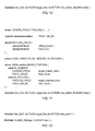
- the function call Set_QoS() takes three arguments: a FLOW data structure; an ACTION data structure; and a FLAG data type.
- the FLOW data structure specifies source and destination addresses for the data packet that will contain the triggering information.
- the ACTION data structure contains among other things the parameters for a QoS setting of the output queue in the router associated with the destination address contained in the FLOW data structure.
- the FLAG data type specifies whether to immediately put into effect the QoS setting, or to delay the QoS setting.
- the video server when the video server decides that a change in QoS is appropriate, it communicates with the service software 212 in the controller portion 210 of router 102.
- the server transmits new QoS information to the flow control table by way of the service software 212 to the API 214.
- the service software 212 could be a program written by a mobile code, such as Java, and sent by the video server at the beginning of service.
- the service software and the video server can retain a communication path (e.g., TCP/IP, UDP/IP, etc.) over the network connection.
- a communication path e.g., TCP/IP, UDP/IP, etc.
- CORBA Common Object Request Broker Architecture
- the objects consisting the service software and (part of) the video server can communicate via a mechanism called IIOP (Internet Inter-ORB Protocol; ORB: Object Request Broker), based on TCP/IP and physically can go over any network connection (e.g., LAN, WAN, etc.).
- IIOP Internet Inter-ORB Protocol
- ORB Object Request Broker
- the service software uses this information for the API function call Set_Qos(). More particularly, the information specifies the target_flow argument, the new_action argument, and the flag argument.
- Set_Qos() looks for a matching entry in the flow table that matches the information contained in the target_flow argument. If the flag argument is CHANGE_IMMEDIATE, then the new_action argument is written to the ACTION field 320 of the matching entry. If the flag argument is CHANGE_SYNCHRONOUS, then the NEW_ACTION field in the entry is filled with information from the new_action argument, and the corresponding FLAG field 330 is set.
- special data packets can be defined which contain the same information.
- the forwarding controller 226 would detect the special packets.
- the forwarding controller would contain logic or code to extract the information from the special packets and feed them directly to the appropriate fields in the flow control table 227.
- a special packet can be defined by assigning a predetermined location in the packet to contain a one-bit "flag". The flag can be used to show that the packet is a special data packet with the new QoS information.
- FIG. 7 illustrates another embodiment of flow control table 227, having fields similar to the flow control table illustrated in Fig. 3.
- the flow control table shown in Fig. 7 includes entries 1, 2, 3,... N. Each entry comprises a FLOW field 710, an ACTION field 720, a MASK field 730, and a NEW_ACTION field 740.
- the FLOW field 710 further comprises a source address sub-field 712 and a corresponding destination address sub-field 714.
- the ACTION and NEW_ACTION fields contain QoS parameters which determine the output QoS for an outgoing data packet, as will be explained below.
- the MASK field is a bit pattern.
- Fig. 8 outlines the processing of forwarding controller 226. Processing begins by the arrival of a data packet over network 10 via network interface 222.
- the forwarding controller inspects the contents of the data packet to find a matching entry in flow control table 227, step 802. This is done by matching a source address contained in the received data packet against the source address sub-field 712 of the FLOW field 710 of each entry in the flow control table, and matching a destination address also contained in the received data packet against the destination address sub-field 714 of the FLOW field 710 in each entry of the flow control table.
- a test is made to determine if an entry for the received data packet was found, step 801. If no entry was found, then a DEFAULT_ACTION is taken, step 810, in connection with how the data packet is to be handled. For example, the default action might simply be to dump the packet, without forwarding it. Processing of the received data packet is then concluded.
- a matching entry is found if both the source and destination address sub-fields of its FLOW field 710 matches the source and destination fields contained in the received data packet If a matching entry is found, processing proceeds to a second test at step 803. Here, the MASK field 730 of the matching entry in the flow control table 227 is tested . If the mask value in the MASK field 730 is all zeroes, then processing proceeds to step 804. At step 804, the received data packet is transmitted from the router 102. The output QoS of the transmitted data packet is determined by the parameters contained in the ACTION field 720 of the matching entry. Processing of the packet is then concluded.
- the MASK field is compared to a predetermined portion of the data packet containing a similar sized mask field.
- the predetermined field can be the type of service (TOS) field in the IP header of the data packet. If the MASK does not match the predetermined portion of the data packet, then processing proceeds according to step 804.
- the data packet is transmitted with an output QoS determined by the QoS parameters contained in the ACTION field 720 of the matching entry which concludes processing of the data packet.
- processing proceeds to step 806.
- the information contained in the NEW_ACTION field 740 of the matching entry is copied to the ACTION field 720 of that entry. Detecting the presence of the information in the predetermined portion of the data packet triggers the copying of the contents in the NEW_ACTION field to the ACTION field.
- the MASK field 730 of the matching entry is cleared (i.e., set to all zeroes), step 808.
- the data packet is then transmitted, step 804, with an output QoS determined by the QoS parameters contained in the ACTION field 720 of the matching entry.
- the parameters contained in the ACTION field are those obtained from the NEW_ACTION field 740.
- the data packet will be transmitted in step 804 with a new QoS setting. Processing of the received data packet is then concluded.
- Fig. 9 shows the process flow in the forwarding controller 226 in accordance with a variation of the second embodiment of the invention.
- processing begins by the arrival of a data packet over network 10 via network interface 222.
- the forwarding controller inspects the contents of the data packet to find a matching entry in flow control table 227, step 902.
- the source address contained in the received data packet is matched against the source address sub-field 712 of the FLOW field 710 of each entry in the flow control table.
- a destination address also contained the received data packet likewise is matched against the destination address sub-field 714 of the FLOW field 710 in each entry of the flow control table.
- a test is made to determine if an entry for the received data packet was found, step 901. If no entry was found, then a DEFAULT_ACTION is taken, step 910, in connection with how the data packet is to be handled. For example, the default action might simply be to dump the packet, without forwarding it. Processing for the received data packet then concludes.
- a matching entry is found if both the source and destination address sub-fields of its FLOW field 710 matches the source and destination fields contained in the received data packet. If a matching entry is found, processing proceeds to step 904. Here, the received data packet is transmitted from the router 102. The output QoS of the transmitted data packet is determined by the parameters contained in the ACTION field 720 of the matching entry.
- Processing then proceeds to a test at step 903.
- the MASK field 730 of the matching entry is inspected. If MASK field 730 is all zeroes, then processing of the received packet, which has now been transmitted, concludes.
- MASK field 730 is not all zeroes
- processing proceeds to yet another test at step 905.
- the MASK is compared to the predetermined portion of the data packet. If the predetermined portion does not match the MASK, then processing of the received data packet, which has now been transmitted, concludes.
- step 906 the information contained in the NEW_ACTION field 740 of the matching entry is copied to the ACTION field 720 of that entry.
- the MASK field 730 of the matching entry is set to all zeroes, step 908. Detecting a match with the predetermined portion of the data packet triggers the copying of the contents in the NEW_ACTION field to the ACTION field. Processing of the received data packet, which has now been transmitted, is then concluded.
- the function call Set_QoS() takes three arguments: a FLOW data structure; an ACTION data structure; and a MASK argument.
- the FLOW data structure specifies source and destination addresses for the data packet that will contain the triggering information.
- the ACTION data structure contains among other things the parameters for a QoS setting of the output queue in the router associated with the destination address contained in the FLOW data structure.
- the MASK is an 8-bit bit pattern.
- the video server when it decides that a change in QoS is appropriate, it communicates with the service software 212 in the controller portion 210 of router 102.
- the video server transmits new QoS information to the flow control table by way of the API.
- the service software 212 uses this information for the API function call Set_Qos(). More particularly, the information specifies the target_flow argument, the new_action argument, and the mask argument.
- Set_Qos() looks for a matching entry in the flow table that matches the information contained in the mask argument.
- the NEW_ACTION field 740 of the matching entry is filled with information from the new_action argument, and the value of the mask argument is copied to the corresponding MASK field 730 of the matching entry.
- special data packets can be defined which contain the same information.
- the forwarding controller 226 would detect the special packets.
- Logic or software or the like contained in the forwarding controller would extract the information from the packets and deliver it directly to the appropriate fields in the flow control table 227.
- Fig. 11 shows a variation of the API used to set the flow control table of Fig. 7.
- This variation of the API is quite general, allowing the location of the predetermined portion of the incoming data packet to be defined anywhere within the data packet, in addition to specifying the mask value.
- the predetermined portion can be in the packet header or in the payload itself, at a specified location with a specified length.
- the function call Set_QoS() takes three arguments: a FLOW data structure; an ACTION data structure; and a MASK data structure.
- the FLOW data structure and ACTION data structures are as previously defined.
- the MASK data structure can accommodate header and payload specifications. If the predetermined portion is to be located in the header, then the relevant data structure is the HEADER FIELD. This data structure specifies which field in the header of the data packet that the mask value will be compared against. If the predetermined portion is to be located in the payload, then the relevant data structure is the PAYLOAD_FIELD. This data structure specifies by offset_position where, from the beginning of the payload, the predetermined portion begins. A field_length specifies the length of the field to be compared against the mask value. Whether a HEADER_FIELD or a PAYLOAD_FIELD is specified, there is a field_value which specifies the mask value to be stored in the flow control table.
- FIG. 12 Yet another variation of the API for setting the flow control table of Fig. 7 is illustrated in Fig. 12.
- Multiple invocations of Set_QoS() can be made.
- the mask value to the invocations can be set by a single function call to Commit_Change().
- Each entry affected by a Set_QoS() call would receive the mask value.
- Fig. 13 shows yet a third embodiment of the invention wherein the flow control table 227 incorporates a vector of plural entries of QoS parameters.
- a NEW_ACTION_LIST field 1350 is provided in addition to the FLOW field 1310 and the ACTION field 1320.
- the NEW_ACTION_LIST field 1350 is a pointer to an array of QoS settings 1370. Each entry in the array comprises a MASK field 1330, and a NEW_ACTION field 1340 containing the QoS parameters.
- the particular QoS level chosen depends on the which MASK field 1330 matches the bit pattern contained in the predetermined location of the received data packet.
- the API for setting this variation of the flow control table can be readily obtained by making appropriate modifications to the embodiments of API's illustrated in Figs. 10 - 12.
- the MASK and ACTION data structures would be altered to be lists instead of single element structures.
- the NEW_ACTION_LIST can have a persistent mode.
- the MASK field is cleared upon changing the QoS setting.
- step 808 in Fig. 8 is a step of clearing the MASK field.
- the MASK field remains unaffected until it is explicitly deleted. This can be implemented by providing an appropriate API.
- Providing for a persistent mode feature in the flow control table of Fig. 13 would be useful for traffic flow situations where the pattern of bandwidth requirements is known. For example, in the case of a video stream, the bandwidth requirements for different scenes in the video vary. Thus, it is possible to vary the bandwidth requirements of the network as a function of the video content. In addition, this information can be determined a priori for the entire video stream.
- the video server 100 can program the flow control table of Fig. 13 with the QoS parameters comprising the list of QoS settings in array 1370 by an appropriate API.
- an appropriate protocol can be defined to provide a list of QoS parameters by way of special data packets.
- the video server sets mask values in the appropriate video data packets to select the QoS in the router 102 according to the bandwidth required for the different scenes in the video transmission. For example, the first packet of each scene would provided with a mask value to select the QoS needed for that scene. Upon receiving this packet, the router will set the output QoS accordingly. When the video scene changes, the first packet in the next scene will have a different mask value, one that will select an appropriate QoS in the router. By adjusting the flow control table dynamically in this way, the usage of the router resources can be made efficient. Resources would be released when the bandwidth requirement of the video is lessened, and vice-versa, thus minimizing the consumption of resources.
- the API shown in Fig. 6 can also be used in a similar manner. Each time a scene change is about to occur, the video server can invoke the API using the CHANGE_IMMEDIATE flag.
- the forgoing discussion can be readily extended to include network devices other than router devices.
- the service provider dos not have its own router. Routers and switches are maintained by the network providers.
- the communication path may traverse multiple network domains.
- the present invention can be readily adapted by persons of ordinary skill in the art to switching devices and in general to network devices along the communication path between the server and the client. For example, the QoS settings in two or more network devices along the communication path from the server to the client can be adjusted in accordance with the invention.
- Device addressing information can be readily incorporated to identify the network device(s) of interest, so that subsequent QoS parameters can be communicated thereto. Multicast transmissions can be used in cases where multiple network devices can share the same QoS parameters.
- video server disclosed herein is simply an example by which the inventive features and aspects of the present invention can be presented.
- the invention is applicable to data servers in general and should not be construed as being limited to video servers.
- the present invention enables the data service provider to design new services based on finer control of the data transmission resources.
- the service provider can control the service changes in terms of time clicks, on the basis of the video content as the video scene changes, as traffic conditions vary, and so on.
- Service can be incorporated with the accounting and/or billing policies of the provider, where customers at the client end pay the provider depending on the quality of services that they desire.
- the invention can be utilized to increase effective usage of network resources.
Landscapes
- Engineering & Computer Science (AREA)
- Computer Networks & Wireless Communication (AREA)
- Signal Processing (AREA)
- Data Exchanges In Wide-Area Networks (AREA)
- Communication Control (AREA)
Applications Claiming Priority (2)
| Application Number | Priority Date | Filing Date | Title |
|---|---|---|---|
| US516331 | 2000-03-01 | ||
| US09/516,331 US6944169B1 (en) | 2000-03-01 | 2000-03-01 | Method and apparatus for managing quality of service in network devices |
Publications (3)
| Publication Number | Publication Date |
|---|---|
| EP1133111A2 true EP1133111A2 (de) | 2001-09-12 |
| EP1133111A3 EP1133111A3 (de) | 2007-01-03 |
| EP1133111B1 EP1133111B1 (de) | 2010-01-06 |
Family
ID=24055099
Family Applications (1)
| Application Number | Title | Priority Date | Filing Date |
|---|---|---|---|
| EP01104298A Expired - Lifetime EP1133111B1 (de) | 2000-03-01 | 2001-02-22 | Verfahren und Vorrichtung zur Verwaltung von Servicequalität in Netzwerkeinheiten |
Country Status (4)
| Country | Link |
|---|---|
| US (1) | US6944169B1 (de) |
| EP (1) | EP1133111B1 (de) |
| JP (1) | JP4410408B2 (de) |
| DE (1) | DE60140978D1 (de) |
Cited By (2)
| Publication number | Priority date | Publication date | Assignee | Title |
|---|---|---|---|---|
| EP1718079A1 (de) * | 2005-04-29 | 2006-11-02 | Alcatel USA Sourcing, L.P. | System, Verfahren und rechnerlesbares Medium zum schnellen Kanalwechsel |
| WO2008015379A1 (en) * | 2006-07-31 | 2008-02-07 | British Telecommunications Public Limited Company | User prioritisation of communications traffic |
Families Citing this family (37)
| Publication number | Priority date | Publication date | Assignee | Title |
|---|---|---|---|---|
| US8914022B2 (en) | 1992-03-06 | 2014-12-16 | Gogo Llc | System for providing high speed communications service in an airborne wireless cellular network |
| US8457627B2 (en) * | 1999-08-24 | 2013-06-04 | Gogo Llc | Traffic scheduling system for wireless communications |
| US8452276B2 (en) * | 2000-10-11 | 2013-05-28 | Gogo Llc | Differentiated services code point mirroring for wireless communications |
| GB0016185D0 (en) * | 2000-06-30 | 2000-08-23 | Nokia Networks Oy | Dynamic DSCP availability request method |
| US7111163B1 (en) | 2000-07-10 | 2006-09-19 | Alterwan, Inc. | Wide area network using internet with quality of service |
| US20020112244A1 (en) * | 2000-12-19 | 2002-08-15 | Shih-Ping Liou | Collaborative video delivery over heterogeneous networks |
| US20030033467A1 (en) * | 2001-08-08 | 2003-02-13 | Satoshi Yoshizawa | Method and apparatus for resource allocation in network router and switch |
| WO2003049353A1 (en) * | 2001-12-05 | 2003-06-12 | Qualcomm, Incorporated | System and method for adjusting quality of service in a communication system |
| US7802008B2 (en) * | 2002-08-12 | 2010-09-21 | Matsushita Electric Industrial Co., Ltd. | Quality of service management in network gateways |
| US7743166B2 (en) * | 2003-04-04 | 2010-06-22 | Ellacoya Networks, Inc. | Scaleable flow-based application and subscriber traffic control |
| US20050021718A1 (en) * | 2003-05-09 | 2005-01-27 | Palliser Networks, Inc. | Centrally managed differentiated service |
| US20050005105A1 (en) * | 2003-06-24 | 2005-01-06 | Brown Larry Cecil | Remote access control feature for limiting access to configuration file components |
| FR2856813B1 (fr) * | 2003-06-27 | 2005-09-23 | Cit Alcatel | Traitement d'adresses de terminaux de communication, par integration et/ou extraction de caracteristiques d'interface de communication dans l'adresse |
| US20070261082A1 (en) * | 2003-08-22 | 2007-11-08 | Interuniversitair Microelektronica Centrum (Imec) | Method for operating a multi-media wireless system in a multi-user environment |
| US20060114836A1 (en) * | 2004-08-20 | 2006-06-01 | Sofie Pollin | Method for operating a combined multimedia -telecom system |
| FI116592B (fi) * | 2003-11-24 | 2005-12-30 | Nokia Corp | Päätelaitteen konfigurointi |
| US8442519B2 (en) | 2003-12-07 | 2013-05-14 | Gogo Llc | Spectrum sharing between an aircraft-based air-to-ground communication system and existing geostationary satellite services |
| US20060193327A1 (en) * | 2005-02-25 | 2006-08-31 | International Business Machines Corporation | System and method for providing quality of service in a virtual adapter |
| US7636801B1 (en) | 2005-06-20 | 2009-12-22 | Symantec Operating Corporation | Coordination of quality of service in a multi-layer virtualized storage environment |
| US8259566B2 (en) * | 2005-09-20 | 2012-09-04 | Qualcomm Incorporated | Adaptive quality of service policy for dynamic networks |
| US7852853B1 (en) | 2006-02-07 | 2010-12-14 | Nextel Communications Inc. | System and method for transmitting video information |
| CN1859306A (zh) * | 2006-02-21 | 2006-11-08 | 华为技术有限公司 | 一种提供QoS服务的方法和系统 |
| US8194657B2 (en) * | 2007-05-22 | 2012-06-05 | Actiontec Electronics, Inc. | Systems and methods for dynamic quality of service |
| KR101502014B1 (ko) * | 2009-01-15 | 2015-03-12 | 엘지전자 주식회사 | 화상 회의 시스템 및 그 방법 |
| KR101545587B1 (ko) | 2009-01-15 | 2015-08-19 | 엘지전자 주식회사 | 화상 회의 시스템 및 그 방법 |
| US8270425B2 (en) * | 2009-12-29 | 2012-09-18 | Symbol Technologies, Inc. | Method and system for multicast video streaming over a wireless local area network (WLAN) |
| EP2530988B1 (de) * | 2011-06-04 | 2015-09-16 | Alcatel Lucent | Zeitplanungskonzept |
| US8873403B2 (en) * | 2012-02-21 | 2014-10-28 | Avaya Inc. | System and method for automatic DSCP tracing for XoIP elements |
| US9438524B2 (en) | 2012-02-29 | 2016-09-06 | Avaya Inc. | System and method for verifying multiprotocol label switching contracts |
| JP6060051B2 (ja) * | 2013-08-08 | 2017-01-11 | アラクサラネットワークス株式会社 | パケット中継装置及びパケット中継方法 |
| US9319307B2 (en) | 2013-09-06 | 2016-04-19 | At&T Intellectual Property I, L.P. | Providing differentiated service to traffic flows obscured by content distribution systems |
| WO2016088244A1 (ja) * | 2014-12-05 | 2016-06-09 | 富士通株式会社 | サーバの画像配信方法 |
| US10103997B2 (en) | 2016-06-01 | 2018-10-16 | At&T Intellectual Property I, L.P. | Dynamic quality of service for over-the-top content |
| US11194558B2 (en) * | 2016-10-14 | 2021-12-07 | Accenture Global Solutions Limited | Application migration system |
| EP4272083B1 (de) * | 2020-12-30 | 2026-01-28 | Oracle International Corporation | Klassenbasiertes queueing für skalierbaren multi-tenant-rdma-verkehr |
| US12375561B2 (en) | 2020-12-30 | 2025-07-29 | Oracle International Corporation | Cloud scale multi-tenancy for RDMA over converged ethernet (RoCE) |
| US12375562B2 (en) | 2020-12-30 | 2025-07-29 | Oracle International Corporation | Class-based queueing for scalable multi-tenant RDMA traffic |
Family Cites Families (21)
| Publication number | Priority date | Publication date | Assignee | Title |
|---|---|---|---|---|
| US5768527A (en) | 1996-04-23 | 1998-06-16 | Motorola, Inc. | Device, system and method of real-time multimedia streaming |
| GB2312592A (en) | 1996-04-24 | 1997-10-29 | Ibm | Quality of service parameters |
| FI103455B (fi) * | 1996-10-08 | 1999-06-30 | Nokia Telecommunications Oy | Pakettiverkon reititin |
| US6335927B1 (en) | 1996-11-18 | 2002-01-01 | Mci Communications Corporation | System and method for providing requested quality of service in a hybrid network |
| US6292465B1 (en) | 1997-05-27 | 2001-09-18 | Ukiah Software, Inc. | Linear rule based method for bandwidth management |
| US6341309B1 (en) | 1997-05-27 | 2002-01-22 | Novell, Inc. | Firewall system for quality of service management |
| US6104700A (en) | 1997-08-29 | 2000-08-15 | Extreme Networks | Policy based quality of service |
| US6327254B1 (en) | 1997-10-14 | 2001-12-04 | Lucent Technologies Inc. | Method for bandwidth sharing in a multiple access system for communications networks |
| US6226277B1 (en) | 1997-10-14 | 2001-05-01 | Lucent Technologies Inc. | Method for admitting new connections based on usage priorities in a multiple access system for communications networks |
| US6308216B1 (en) * | 1997-11-14 | 2001-10-23 | International Business Machines Corporation | Service request routing using quality-of-service data and network resource information |
| US6091709A (en) | 1997-11-25 | 2000-07-18 | International Business Machines Corporation | Quality of service management for packet switched networks |
| US6154776A (en) * | 1998-03-20 | 2000-11-28 | Sun Microsystems, Inc. | Quality of service allocation on a network |
| US6317438B1 (en) | 1998-04-14 | 2001-11-13 | Harold Herman Trebes, Jr. | System and method for providing peer-oriented control of telecommunications services |
| US6157955A (en) * | 1998-06-15 | 2000-12-05 | Intel Corporation | Packet processing system including a policy engine having a classification unit |
| US6246702B1 (en) | 1998-08-19 | 2001-06-12 | Path 1 Network Technologies, Inc. | Methods and apparatus for providing quality-of-service guarantees in computer networks |
| US6286052B1 (en) * | 1998-12-04 | 2001-09-04 | Cisco Technology, Inc. | Method and apparatus for identifying network data traffic flows and for applying quality of service treatments to the flows |
| US6466984B1 (en) * | 1999-07-02 | 2002-10-15 | Cisco Technology, Inc. | Method and apparatus for policy-based management of quality of service treatments of network data traffic flows by integrating policies with application programs |
| US6745246B1 (en) * | 2000-01-28 | 2004-06-01 | Advanced Micro Devices, Inc. | Apparatus and method in a network switch for modifying a bandwidth request between a requestor and a router |
| US6732168B1 (en) * | 2000-07-05 | 2004-05-04 | Lucent Technologies Inc. | Method and apparatus for use in specifying and insuring policies for management of computer networks |
| US6763392B1 (en) * | 2000-09-29 | 2004-07-13 | Microsoft Corporation | Media streaming methods and arrangements |
| US6661780B2 (en) * | 2001-12-07 | 2003-12-09 | Nokia Corporation | Mechanisms for policy based UMTS QoS and IP QoS management in mobile IP networks |
-
2000
- 2000-03-01 US US09/516,331 patent/US6944169B1/en not_active Expired - Fee Related
- 2000-12-08 JP JP2000374073A patent/JP4410408B2/ja not_active Expired - Fee Related
-
2001
- 2001-02-22 DE DE60140978T patent/DE60140978D1/de not_active Expired - Fee Related
- 2001-02-22 EP EP01104298A patent/EP1133111B1/de not_active Expired - Lifetime
Non-Patent Citations (1)
| Title |
|---|
| A. BANCHS ET AL.: "Multicasting multimedia streams with active networks", PROCEEDINGS OF THE ANNUAL CONFERENCE ON LOCAL COMPUTER NETWORKS, LCN, 1998, pages 150 - 159 |
Cited By (4)
| Publication number | Priority date | Publication date | Assignee | Title |
|---|---|---|---|---|
| EP1718079A1 (de) * | 2005-04-29 | 2006-11-02 | Alcatel USA Sourcing, L.P. | System, Verfahren und rechnerlesbares Medium zum schnellen Kanalwechsel |
| CN1921615B (zh) * | 2005-04-29 | 2010-08-18 | 美国阿尔卡特资源有限合伙公司 | 用于快速频道改变的系统、方法 |
| US8281351B2 (en) | 2005-04-29 | 2012-10-02 | Alcatel Lucent | System, method, and computer readable medium rapid channel change |
| WO2008015379A1 (en) * | 2006-07-31 | 2008-02-07 | British Telecommunications Public Limited Company | User prioritisation of communications traffic |
Also Published As
| Publication number | Publication date |
|---|---|
| EP1133111B1 (de) | 2010-01-06 |
| JP2001244987A (ja) | 2001-09-07 |
| DE60140978D1 (de) | 2010-02-25 |
| EP1133111A3 (de) | 2007-01-03 |
| US6944169B1 (en) | 2005-09-13 |
| JP4410408B2 (ja) | 2010-02-03 |
Similar Documents
| Publication | Publication Date | Title |
|---|---|---|
| US6944169B1 (en) | Method and apparatus for managing quality of service in network devices | |
| US7230921B2 (en) | Concurrent use of communication paths in a multi-path access link to an IP network | |
| US10200251B2 (en) | Methods and apparatus for accessing selectable application processing of data packets in an adaptive private network | |
| US7149222B2 (en) | Integrated access point network device | |
| Scharf et al. | Multipath TCP (MPTCP) application interface considerations | |
| US6937566B1 (en) | Dynamic quality of service reservation in a mobile communications network | |
| US20030033467A1 (en) | Method and apparatus for resource allocation in network router and switch | |
| US20070008884A1 (en) | Immediate ready implementation of virtually congestion free guarantedd service capable network | |
| US20090274045A1 (en) | Qos provisioning in a network having dynamic link states | |
| US6973102B2 (en) | Jitter reduction in differentiated services (DiffServ) networks | |
| JP2012075173A (ja) | 動的なモードドリブンリンク管理のためのシステム及び方法 | |
| US20040071087A1 (en) | System and method for load balancing | |
| US7773624B2 (en) | Network system and method with centralized flow behavioral mapping between layers | |
| WO2008110955A2 (en) | Applying policies for managing a service flow | |
| EP1134941A1 (de) | Verfahren und Anordnung zur Flusssteuerung | |
| US20020057654A1 (en) | Method and apparatus for frame peeking | |
| JP2001045066A (ja) | IP通信ネットワークシステム及びQoS保証装置 | |
| US20190273682A1 (en) | Method and system for managing network communications | |
| JP2003524994A (ja) | Wan又はlanにおけるインターネット・プロトコルのトラフィックを制御する方法及び装置 | |
| Hou et al. | A differentiated services architecture for multimedia streaming in next generation Internet | |
| Adami et al. | TCP/IP-based multimedia applications and services over satellite links: experience from an ASI/CNIT project | |
| US20030084186A1 (en) | Method and apparatus for programmable network router and switch | |
| Al-Haddad et al. | A Survey of Quality of Service (QoS) Protocols and Software-Defined Networks (SDN) From the Traditional to the Latest Network Architecture | |
| US8027343B2 (en) | Communication system, computer, and method for determining a communication protocol to be used in a communication system | |
| US20060198378A1 (en) | Scheduling technique for mobile uplink transmission |
Legal Events
| Date | Code | Title | Description |
|---|---|---|---|
| PUAI | Public reference made under article 153(3) epc to a published international application that has entered the european phase |
Free format text: ORIGINAL CODE: 0009012 |
|
| AK | Designated contracting states |
Kind code of ref document: A2 Designated state(s): AT BE CH CY DE DK ES FI FR GB GR IE IT LI LU MC NL PT SE TR |
|
| AX | Request for extension of the european patent |
Free format text: AL;LT;LV;MK;RO;SI |
|
| 17P | Request for examination filed |
Effective date: 20060331 |
|
| PUAL | Search report despatched |
Free format text: ORIGINAL CODE: 0009013 |
|
| AK | Designated contracting states |
Kind code of ref document: A3 Designated state(s): AT BE CH CY DE DK ES FI FR GB GR IE IT LI LU MC NL PT SE TR |
|
| AX | Request for extension of the european patent |
Extension state: AL LT LV MK RO SI |
|
| AKX | Designation fees paid |
Designated state(s): DE FR GB |
|
| 17Q | First examination report despatched |
Effective date: 20080407 |
|
| GRAP | Despatch of communication of intention to grant a patent |
Free format text: ORIGINAL CODE: EPIDOSNIGR1 |
|
| GRAS | Grant fee paid |
Free format text: ORIGINAL CODE: EPIDOSNIGR3 |
|
| GRAA | (expected) grant |
Free format text: ORIGINAL CODE: 0009210 |
|
| AK | Designated contracting states |
Kind code of ref document: B1 Designated state(s): DE FR GB |
|
| REG | Reference to a national code |
Ref country code: GB Ref legal event code: FG4D |
|
| REF | Corresponds to: |
Ref document number: 60140978 Country of ref document: DE Date of ref document: 20100225 Kind code of ref document: P |
|
| PLBE | No opposition filed within time limit |
Free format text: ORIGINAL CODE: 0009261 |
|
| STAA | Information on the status of an ep patent application or granted ep patent |
Free format text: STATUS: NO OPPOSITION FILED WITHIN TIME LIMIT |
|
| REG | Reference to a national code |
Ref country code: FR Ref legal event code: ST Effective date: 20101029 |
|
| 26N | No opposition filed |
Effective date: 20101007 |
|
| PG25 | Lapsed in a contracting state [announced via postgrant information from national office to epo] |
Ref country code: FR Free format text: LAPSE BECAUSE OF NON-PAYMENT OF DUE FEES Effective date: 20100308 |
|
| PG25 | Lapsed in a contracting state [announced via postgrant information from national office to epo] |
Ref country code: DE Free format text: LAPSE BECAUSE OF NON-PAYMENT OF DUE FEES Effective date: 20100901 |
|
| PGFP | Annual fee paid to national office [announced via postgrant information from national office to epo] |
Ref country code: GB Payment date: 20150218 Year of fee payment: 15 |
|
| GBPC | Gb: european patent ceased through non-payment of renewal fee |
Effective date: 20160222 |
|
| PG25 | Lapsed in a contracting state [announced via postgrant information from national office to epo] |
Ref country code: GB Free format text: LAPSE BECAUSE OF NON-PAYMENT OF DUE FEES Effective date: 20160222 |