EP1133414B1 - Verfahren zur datenübertragung zwischen einem steuergerät für rückhalteeinrichtungen und sensoren - Google Patents
Verfahren zur datenübertragung zwischen einem steuergerät für rückhalteeinrichtungen und sensoren Download PDFInfo
- Publication number
- EP1133414B1 EP1133414B1 EP00963934A EP00963934A EP1133414B1 EP 1133414 B1 EP1133414 B1 EP 1133414B1 EP 00963934 A EP00963934 A EP 00963934A EP 00963934 A EP00963934 A EP 00963934A EP 1133414 B1 EP1133414 B1 EP 1133414B1
- Authority
- EP
- European Patent Office
- Prior art keywords
- sensors
- control unit
- data
- sensor
- bits
- Prior art date
- Legal status (The legal status is an assumption and is not a legal conclusion. Google has not performed a legal analysis and makes no representation as to the accuracy of the status listed.)
- Expired - Lifetime
Links
Images

Classifications
-
- B—PERFORMING OPERATIONS; TRANSPORTING
- B60—VEHICLES IN GENERAL
- B60R—VEHICLES, VEHICLE FITTINGS, OR VEHICLE PARTS, NOT OTHERWISE PROVIDED FOR
- B60R21/00—Arrangements or fittings on vehicles for protecting or preventing injuries to occupants or pedestrians in case of accidents or other traffic risks
- B60R21/01—Electrical circuits for triggering passive safety arrangements, e.g. airbags, safety belt tighteners, in case of vehicle accidents or impending vehicle accidents
-
- H—ELECTRICITY
- H04—ELECTRIC COMMUNICATION TECHNIQUE
- H04L—TRANSMISSION OF DIGITAL INFORMATION, e.g. TELEGRAPHIC COMMUNICATION
- H04L12/00—Data switching networks
- H04L12/28—Data switching networks characterised by path configuration, e.g. LAN [Local Area Networks] or WAN [Wide Area Networks]
- H04L12/40—Bus networks
- H04L12/403—Bus networks with centralised control, e.g. polling
-
- B—PERFORMING OPERATIONS; TRANSPORTING
- B60—VEHICLES IN GENERAL
- B60R—VEHICLES, VEHICLE FITTINGS, OR VEHICLE PARTS, NOT OTHERWISE PROVIDED FOR
- B60R21/00—Arrangements or fittings on vehicles for protecting or preventing injuries to occupants or pedestrians in case of accidents or other traffic risks
- B60R21/01—Electrical circuits for triggering passive safety arrangements, e.g. airbags, safety belt tighteners, in case of vehicle accidents or impending vehicle accidents
- B60R2021/0104—Communication circuits for data transmission
- B60R2021/01047—Architecture
- B60R2021/01054—Bus
- B60R2021/01068—Bus between different sensors and airbag control unit
-
- B—PERFORMING OPERATIONS; TRANSPORTING
- B60—VEHICLES IN GENERAL
- B60R—VEHICLES, VEHICLE FITTINGS, OR VEHICLE PARTS, NOT OTHERWISE PROVIDED FOR
- B60R21/00—Arrangements or fittings on vehicles for protecting or preventing injuries to occupants or pedestrians in case of accidents or other traffic risks
- B60R21/01—Electrical circuits for triggering passive safety arrangements, e.g. airbags, safety belt tighteners, in case of vehicle accidents or impending vehicle accidents
- B60R2021/0104—Communication circuits for data transmission
- B60R2021/01102—Transmission method
- B60R2021/01115—Transmission method specific data frames
-
- H—ELECTRICITY
- H04—ELECTRIC COMMUNICATION TECHNIQUE
- H04L—TRANSMISSION OF DIGITAL INFORMATION, e.g. TELEGRAPHIC COMMUNICATION
- H04L12/00—Data switching networks
- H04L12/28—Data switching networks characterised by path configuration, e.g. LAN [Local Area Networks] or WAN [Wide Area Networks]
- H04L12/40—Bus networks
- H04L2012/40267—Bus for use in transportation systems
- H04L2012/40273—Bus for use in transportation systems the transportation system being a vehicle
Definitions
- the invention relates to a method for data transmission between a control device for retaining devices and sensors.
- the invention has for its object to provide a method of specify the type mentioned above, with a flexible temporal access from the control unit to the measured data of the individual sensors is possible.
- control unit a Request telegram sent to the sensors and that each sensor from the comparison of the request telegram with his own address, whether and in which one Time slot he transmitted his data to the control unit should.
- This allows the individual sensors for the Transmission of their measured data to the control unit flexible Time slots are allocated. That is, they can Priorities of the individual sensors to different Vehicle types or accident scenarios.
- sensors whose recorded measured values with the least possible time delay from the control unit to process their data in time slots Transmit, which are at the end of the time slot sequence.
- the controller transmits together with the request telegram several control bits on the Bus line, which corresponds to the request telegram addressed sensors that they either a certain of several existing in them Memory registers are to select so that in it Information can be inscribed and read, or that in the selected memory register information be inscribed, or that from the selected Memory register an information is to be read, or that measurement data should be sent to the controller.
- the block diagram in Figure 1 shows a control unit SG, the with the help of an algorithm the triggering of several not represented, arranged in a vehicle Retaining controls.
- This Retaining devices may be various types of airbags are installed in different places in the vehicle, or belt tensioners or roll bars or others Occupant protection devices include.
- Occupant protection devices include.
- the control unit SG requires measured data from several sensors S1, S2, S3, S4, S5, which are accident-specific Record vehicle parameters. Such sensors, of which in 5 are shown by way of example in FIG.
- Acceleration sensors either centrally in the vehicle or in the side, front or rear of the vehicle are arranged, or precrash sensors or Rotation rate sensors for detecting a rollover process or Speed sensors or sensors for monitoring the Interior to the type of seat occupancy or the Determining seating positions of vehicle occupants.
- the Principle includes all kinds of sensors, with which the Type and severity of a vehicle crash and also the Seat occupancy in the vehicle and the positions of Vehicle occupants can be detected to from the measurement data to control the existing restraints so can provide the occupants with optimal protection.
- FIG. 1 shows, all sensors S1 to S5 are over a bus line BL connected to the control unit SG.
- the Bus line BL can have one serial, one ring, one have star-shaped or tree-shaped structure.
- Each sensor S1 to S5 has a series of Memory registers, each of which has a register address is assigned.
- memory registers e.g. a ROM register, PROM register or RAM register in which the Sensor address is stored, other memory registers, in which information about the type of sensor, the Date of manufacture of the relevant sensor, the batch number of the sensor, manufacturer-specific data of the sensor, the ASIC version of the sensor and manufacturer-specific parameters are stored for the Meßsignalausêt.
- Storage registers may be provided in which specifications can be stored for Meß stylistierttes, and other memory registers for recording others Information required for the operation of restraint systems are of importance.
- Some memory registers are written by Control unit SG is inscribed from information and off other memory registers are stored therein Information read from the control unit SG.
- FIG. 2 shows the structure of a data frame for the Case that the control unit SG a specific memory register in a sensor selects and in this selected Memory register writes information.
- the Controller SG to one of the here e.g. five sensors, S1, S2, S3, S4, S5 transmits the message that in this special Sensor selected a very specific memory register shall be.
- This sensor confirms the selection of this Memory register.
- the first eight data bits settle consisting of four control bits and one of four bits existing request telegram.
- the addressed sensor S1 to S5 the Type of information transmitted, whether the sensor in question select a specific memory register should or in a selected memory register a Information is written or read out should or whether the sensor measurement data to the control unit SG should transfer. This consists of four bits Request telegram specifies the address of the selected one Sensors again.
- FIG. 3 shows the structure of the data frame in the event that the control unit SG from a previously selected memory register of a particular sensor S1 until S5 wants to read an information. Then the part begins of the data frame sent from the control unit SG to a sensor S1 to S5 is transmitted, with a start bit, the one Data block of 8 bits, one parity bit and two stop bits consequences.
- the data block again consists of 4 control bits and a 4-bit request telegram.
- the control bits tell the sensor that a selected one Memory register information to be read.
- the request telegram consisting of 4 bits contains the Address of the addressed sensor. After this sensor read out the contents of the selected memory register he transmits it to an 8-bit data block Control unit SG. As usual, the data block is followed by a parity bit.
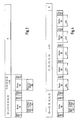
- One for the transmission of measured data from the sensors S1 to S5 to the control unit SG competent data frame is in the Figure 4 shown.
- the part of the data frame in which the control unit SG one or more sensors S1 to S5 asks to transmit their measurement data begins with a Scartbit, which has a data block of 8 bits, a parity bit and two stop bits follow.
- the data block is composed out of 4 control bits and 4 bits for one Request message.
- the control bits inform the Sensors S1 to S5 about that measurement data to the controller SG are to be transferred.
- the request telegram shares the individual sensors S1 to S5 with, which of the sensors in which time slot ZS0, ZS1, ZS2, ZS3, ZS4 its measurement data to transmit to the control unit SG.
- the area of the data frame in which the sensors S1 to S5 transmit their measured data to the control unit SG is divided into five time slots ZS0 to ZS4 in the exemplary embodiment shown.
- the purpose of the following two tables is to clarify how the measured data (consisting of 8 bits, each with one parity bit) of the individual sensors S1 to S5 can be divided into the available time slots ZS0 to ZS4.
- the two tables consist of five columns, with the sensors numbered consecutively in the first column. For example, the two tables assume twelve sensors.
- the second column of the tables shows the addresses of the sensors consisting of 4 bits a0, a1, a2 and a3.
- the first 4 Addresses a0 to a3 are not assigned to specific sensors. These four addresses are reserved for other actions (e.g. Initialization of all sensors in the vehicle) than for the Measurement data transmission of the individual sensors S1 to S5 for Control unit SG.
- the with x labeled bits A2, A1 and A0 in the request message have for the mentioned sensors with the numbers 1, 2, 3 and 4 no meaning. These sensors react with one Measurement data transmission because the most significant bit a3 of their address as the most significant bit A3 of the request telegram a 0 having.
- the other sensors numbered 5 to 12 will be individually addressed by the request telegram and thus asked to send their measurement data in timeslot ZS4. It is in each case that sensor addressed, the sensor address with matches the request telegram in all bits.
- the Time slot allocation to the sensors there is a group (Sensors 1 to 5) constantly in reserved for them Time slots ZS0, ZS1, ZS2 and ZS3 transmit their measurement data, because their measurement data is the highest priority for the Have trigger decision. And there is another group from sensors 5 to 12, of which only one is ever selected for transmitting its measured data in time slot ZS4.
- the emitted from the control unit SG Request telegram have the bit configuration 1011, so On the one hand, all the sensors whose most significant would be Address bits a3 and a2 have the values 10, in the Time slots ZS0, ZS1, ZS2 and ZS3 send their measured data and also the sensor with the sensor address 11 in time slot ZS4 transmit its measured data to the control unit SG.
- the im Request telegram with x marked bits are provided by the Sensors ignored.
- sensors whose measured values as possible time delay are processed by the control unit to transfer their data into time slots at the end of the Time slot sequence lie.
- these timeslots last in the data frame in the bus line coupled, is the time between the measured value acquisition the sensors and the measured value processing of the control unit at the least. It is therefore just such sensors this Time slots that guarantee a high measurement value, assign their timeliness for the triggering of Retaining devices is particularly important. This is true in particular on acceleration sensors to the side Area of the vehicle are arranged, because known for Side crashes the time delay between the Measurement signal detection and the triggering of the restraint devices must be extremely low.
- the data frames described above have a fixed timing on. This allows the individual sensors S1, ... S5, which are synchronized to the clock, on time slots access not solely to themselves, but also on time slots ZS0, ... ZS4, where others Sensors transmit their information. This allows sensors exchange messages with each other. Thus, for example, identical sensors match each other; e.g. turn up similar acceleration sensors on a common Basic value or offset. In another example Sensors for vehicle interior monitoring, which the type of Seat occupancy and the position of the vehicle occupants capture, from a static measuring mode to a dynamic measuring mode switch over when information from other sensors to receive an impending crash.
- the measuring cycle is large (about 100 ⁇ s) is in dynamic Measuring mode, when a crash situation approaches, the measuring cycle much smaller (about 10 ⁇ s). Because the decision whether in the event of a crash the airbags inflated hard or soft or not activated depends decisively on the position of the Vehicle occupants relative to the airbags. But as before a crash can change the position of the occupants very quickly, is a short measurement cycle, corresponds to the dynamic measurement mode, essential.
Landscapes
- Engineering & Computer Science (AREA)
- Computer Networks & Wireless Communication (AREA)
- Signal Processing (AREA)
- Mechanical Engineering (AREA)
- Air Bags (AREA)
- Arrangements For Transmission Of Measured Signals (AREA)
- Small-Scale Networks (AREA)
- Automotive Seat Belt Assembly (AREA)
Description
| Sensor Nr. | Sensoradresse a3...a0 | Anforderungstelegramm A3...A0 | Zeitschlitz | Sendemodus |
| - | 0000 | - | - | Reserviert |
| - | 0001 | - | - | Reserviert |
| - | 0010 | - | - | Reserviert |
| - | 0011 | - | - | Reserviert |
| 1 | 0100 | 0xxx | ZS0 | Sendet ständig |
| 2 | 0101 | 0xxx | ZS1 | Sendet ständig |
| 3 | 0110 | 0xxx | ZS2 | Sendet ständig |
| 4 | 0111 | 0xxx | ZS3 | Sendet ständig |
| 5 | 1000 | 1000 | ZS4 | Sendet auf Anforderung |
| 6 | 1001 | 1001 | ZS4 | Sendet auf Anforderung |
| 7 | 1010 | 1010 | ZS4 | Sendet auf Anforderung |
| 8 | 1011 | 1011 | ZS4 | Sendet auf Anforderung |
| 9 | 1100 | 1100 | ZS4 | Sendet auf Anforderung |
| 10 | 1101 | 1101 | ZS4 | Sendet auf Anforderung |
| 11 | 1110 | 1110 | ZS4 | Sendet auf Anforderung |
| 12 | 1111 | 1111 | ZS4 | Sendet auf Anforderung |
| Sensor Nr. | Sensoradresse A3...a0 | Anforderungstelegramm A3...A0 | Zeitschlitz | Sendemodus |
| - | 0000 | - | - | Reserviert |
| - | 0001 | - | - | Reserviert |
| - | 0010 | - | - | Reserviert |
| - | 0011 | - | - | Reserviert |
| 1 | 0100 | 01xx | ZS0 | Sendet auf Anforderung |
| 2 | 0101 | 01xx | ZS1 | Sendet auf Anforderung |
| 3 | 0110 | 01xx | ZS2 | Sendet auf Anforderung |
| 4 | 0111 | 01xx | ZS3 | Sendet auf Anforderung |
| 5 | 1000 | 10xx | ZS0 | Sendet auf Anforderung |
| 6 | 1001 | 10xx | ZS1 | Sendet auf Anforderung |
| 7 | 1010 | 10xx | ZS2 | Sendet auf Anforderung |
| 8 | 1011 | 10xx | ZS3 | Sendet auf Anforderung |
| 9 | 1100 | xx00 | ZS4 | Sendet auf Anforderung |
| 10 | 1101 | xx01 | ZS4 | Sendet auf Anforderung |
| 11 | 1110 | xx10 | ZS4 | Sendet auf Anforderung |
| 12 | 1111 | xx11 | ZS4 | Sendet auf Anforderung |
Claims (6)
- Verfahren zur Datenübertragung zwischen einem Steuergerät (SG) für Rückhalteeinrichtungen und damit über eine Busleitung (BL) verbundenen Sensoren (S1, ..., S5) zur Erfassung unfallspezifischer Fahrzeugparameter, wobei jedem Sensor (S1,..., S5) eine Adresse (a3, ..., a0) zugeordnet ist, über die er vom Steuergerät (SG) identifiziert werden kann, und jeder Sensor (S1, ..., S5) in einem vorgegebenen Zeitschlitz (ZS0, ..., ZS4) seine Daten über die Busleitung (BL) an das Steuergerät (SG) überträgt, dadurch gekennzeichnet, daß das Steuergerät (SG) ein Anforderungstelegramm (A3, ..., A0) an die Sensoren (S1, ..., S5) aussendet und daß jeder Sensor (S1, ..., S5) aus dem Vergleich des Anforderungstelegramms (A3, ..., A0) mit seiner eigenen Adresse (a3, ..., a0) ableitet, ob und in welchem Zeitschlitz (ZS0, ..., ZS4) er seine Daten an das Steuergerät (SG) übertragen soll.
- Verfahren nach Anspruch 1, dadurch gekennzeichnet, daß sich für die Sensoren (S1, ..., S5) aus der Übereinstimmung zumindest eines Teils seiner aus mehreren Bits (a3, ..., a0) bestehenden Adresse mit zumindest einem Teil des aus mehreren Bits (A3, ..., A0) bestehenden Anforderungstelegramms ergibt, ob der betreffende Sensor (S1, ..., S5) in einem festen Zeitraster (ZS0, ..., ZS4) ständig seine Daten aussenden soll, oder ob er einmalig in einem durch das Anforderungstelegramm gekennzeichneten Zeitschlitz (ZS0, ..., ZS4) seine Daten aussenden soll.
- Verfahren nach Anspruch 2, dadurch gekennzeichnet, daß mit einem Anforderungstelegramm (A3, ..., A0), von dem ein Teil mit einem Teil der Adressen (a3, ..., a0) mehrerer Sensoren (S1, ..., S5) übereinstimmt, diesen mehreren Sensoren Zeitschlitze (ZS0, ..., ZS4) zugewiesen werden.
- Verfahren nach einem der vorhergehenden Ansprüche, dadurch gekennzeichnet, daß Sensoren (S1, ..., S5), deren aufgenommene Meßwerte mit möglichst geringer Zeitverzögerung vom Steuergerät (SG) verarbeitet werden sollen, ihre Daten in Zeitschlitzen (ZS0, ZS1) übertragen, die am Ende der Zeitschlitzfolge (ZS0, ..., ZS4) liegen.
- Verfahren nach Anspruch 1, dadurch gekennzeichnet, daß das Steuergerät (SG) zusammen mit dem Anforderungstelegramm (A3, ..., A0) mehrere Kontrollbits über die Busleitung (BL) überträgt, welche den vom Anforderungstelegramm (A3, ..., A0) angesprochenen Sensoren (S1, ..., S5) mitteilen, daß sie entweder ein bestimmtes von mehreren in ihnen vorhandenen Speicherregistern auswählen sollen, damit darin eine Information eingeschrieben oder ausgelesen werden kann, oder daß in das ausgewählte Speicherregister Informationen eingeschrieben werden sollen, oder daß aus dem ausgewählten Speicherregister eine Information ausgelesen werden soll, oder daß Meßdaten zum Steuergerät (SG) gesendet werden sollen.
- Verfahren nach einem der vorhergehenden Ansprüche, dadurch gekennzeichnet, daß Sensoren (S1, ... S5) untereinander Informationen austauschen, indem von den miteinander kommunizierenden Sensoren (S1, ... S5) jeder Sensor auf den (die) zu dem (den) anderen Sensor(en) gehörenden Zeitschlitz(en) (ZS0, ..., ZS4) im Datenrahmen zugreift.
Applications Claiming Priority (3)
| Application Number | Priority Date | Filing Date | Title |
|---|---|---|---|
| DE19945614A DE19945614C1 (de) | 1999-09-23 | 1999-09-23 | Verfahren zur Datenübertragung zwischen einem Steuergerät für Rückhalteeinrichtungen und Sensoren |
| DE19945614 | 1999-09-23 | ||
| PCT/DE2000/002948 WO2001021447A1 (de) | 1999-09-23 | 2000-08-29 | Verfahren zur datenübertragung zwischen einem steuergerät für rückhalteeinrichtungen und sensoren |
Publications (2)
| Publication Number | Publication Date |
|---|---|
| EP1133414A1 EP1133414A1 (de) | 2001-09-19 |
| EP1133414B1 true EP1133414B1 (de) | 2003-10-29 |
Family
ID=7923044
Family Applications (1)
| Application Number | Title | Priority Date | Filing Date |
|---|---|---|---|
| EP00963934A Expired - Lifetime EP1133414B1 (de) | 1999-09-23 | 2000-08-29 | Verfahren zur datenübertragung zwischen einem steuergerät für rückhalteeinrichtungen und sensoren |
Country Status (6)
| Country | Link |
|---|---|
| US (1) | US6836714B1 (de) |
| EP (1) | EP1133414B1 (de) |
| JP (1) | JP4646176B2 (de) |
| AU (1) | AU766702B2 (de) |
| DE (2) | DE19945614C1 (de) |
| WO (1) | WO2001021447A1 (de) |
Families Citing this family (31)
| Publication number | Priority date | Publication date | Assignee | Title |
|---|---|---|---|---|
| US7774115B2 (en) * | 1995-10-30 | 2010-08-10 | Automotive Technologies International, Inc. | Electronics-containing airbag module |
| DE10106181C1 (de) * | 2001-02-10 | 2002-08-22 | Bosch Gmbh Robert | Verfahren zur Klassifizierung eines Überrollvorgangs eines Fahrzeugs |
| DE10109043C1 (de) * | 2001-02-24 | 2002-07-25 | Bosch Gmbh Robert | Verfahren zur Auslösung wenigstens eines Airbags in einem Fahrzeug |
| JP4685289B2 (ja) * | 2001-09-03 | 2011-05-18 | 本田技研工業株式会社 | 衝突判定システム |
| DE10149332A1 (de) | 2001-10-06 | 2003-04-30 | Bosch Gmbh Robert | Verfahren zur Übertragung von Daten von wenigstens einem Sensor zu einem Steuergerät |
| DE10238529A1 (de) * | 2002-08-22 | 2004-03-04 | Robert Bosch Gmbh | Steuergerät |
| DE10241993B3 (de) * | 2002-09-11 | 2004-04-08 | Siemens Ag | Vorrichtung und Verfahren zum Erfassen eines Objektes oder einer Person im Innenraum eines Fahrzeugs |
| DE10321679B4 (de) | 2003-05-14 | 2006-11-30 | Siemens Ag | Verfahren und Vorrichtung zur Übertragung von Daten zwischen einem zentralen Steuergerät eines Insassenschutzsystems in einem Fahrzeug und mindestens einer dezentralen Sensoreinheit |
| DE10333989A1 (de) * | 2003-07-25 | 2005-03-03 | Robert Bosch Gmbh | Verfahren zur digitalen Datenübertragung von einem Sensor zu einem Steuergerät |
| DE102005014783A1 (de) * | 2005-03-31 | 2006-10-05 | Siemens Ag | Verfahren und Vorrichtungen zum Übertragen von Daten auf eine Datenleitung zwischen einem Steuergerät und zumindest einem dezentralen Datenverarbeitungsgerät |
| DE102005014782A1 (de) * | 2005-03-31 | 2006-10-05 | Siemens Ag | Verfahren und Vorrichtung zum Übertragen von Daten auf einer Datenleitung zwischen einem Steuergerät und einem dezentralen Datenverarbeitungsgerät |
| DE102005025519A1 (de) * | 2005-06-03 | 2006-12-07 | Robert Bosch Gmbh | Verfahren zum Betreiben eines Bussystems, Bussystem und Busteilnehmer |
| JP2007008392A (ja) * | 2005-07-01 | 2007-01-18 | Denso Corp | 乗員保護システム |
| JP2007030766A (ja) * | 2005-07-28 | 2007-02-08 | Denso Corp | 乗員保護システム |
| DE102005036050B4 (de) | 2005-08-01 | 2019-03-07 | Robert Bosch Gmbh | Steuergerät zur Ansteuerung von Personenschutzmitteln |
| DE102007006757B4 (de) * | 2007-02-12 | 2013-01-17 | Günter Fendt | Kraftfahrzeug-Sicherheitssystem zur Unterstützung und/oder Schutzgewährung von Fahrzeugführern bei kritischen Fahrsituationen sowie Kraftfahrzeug |
| EP2134023A1 (de) * | 2008-06-10 | 2009-12-16 | Siemens Aktiengesellschaft | Verfahren zur Kommunikation in einem Drahtlosnetzwerk |
| DE102009003282A1 (de) * | 2009-05-20 | 2010-11-25 | Robert Bosch Gmbh | Verfahren zur Auswahl bestimmter Aktivitäten einer Vielzahl von Sensoren, Steuerzentrale, Sensor und Sensorsystem |
| JP5120486B2 (ja) | 2010-11-25 | 2013-01-16 | 株式会社デンソー | 乗員保護システムの通信装置 |
| DE102011018630B4 (de) * | 2011-04-21 | 2013-02-07 | Phoenix Contact Gmbh & Co. Kg | Sicherheits-Kommunikationssystem zur Signalisierung von Systemzuständen |
| DE102011075862B4 (de) * | 2011-05-16 | 2022-06-23 | Bayerische Motoren Werke Aktiengesellschaft | Kraftfahrzeug mit einem Airbag-System |
| US9802568B1 (en) | 2015-09-04 | 2017-10-31 | Waymo Llc | Interlocking vehicle airbags |
| US9817397B1 (en) | 2015-09-04 | 2017-11-14 | Waymo Llc | Active safety mechanisms for an autonomous vehicle |
| US9849852B1 (en) * | 2015-09-04 | 2017-12-26 | Waymo Llc | Intelligent deployment of safety mechanisms for autonomous vehicles |
| US10079650B2 (en) | 2015-12-04 | 2018-09-18 | Infineon Technologies Ag | Robust high speed sensor interface for remote sensors |
| KR102525295B1 (ko) * | 2016-01-06 | 2023-04-25 | 삼성전자주식회사 | 데이터 관리 방법 및 장치 |
| WO2017125512A1 (en) * | 2016-01-20 | 2017-07-27 | Koninklijke Philips N.V. | Occupancy sensing system and sensing method |
| US10635619B2 (en) | 2016-10-12 | 2020-04-28 | Cirrus Logic, Inc. | Encoding for multi-device synchronization of devices |
| US11203318B2 (en) | 2018-06-18 | 2021-12-21 | Waymo Llc | Airbag extension system |
| KR102594272B1 (ko) * | 2021-08-31 | 2023-10-25 | 캐롯손해보험 주식회사 | 사고 감지 방법 및 장치 |
| DE102025115428B3 (de) | 2025-04-22 | 2026-05-07 | Audi Aktiengesellschaft | Stabilitätssystem und Verfahren für ein aktives Fahrwerk eines Kraftfahrzeugs |
Citations (1)
| Publication number | Priority date | Publication date | Assignee | Title |
|---|---|---|---|---|
| WO1989009146A1 (fr) * | 1988-04-02 | 1989-10-05 | Robert Bosch Gmbh | Dispositif electronique de securite pour passagers de vehicules |
Family Cites Families (11)
| Publication number | Priority date | Publication date | Assignee | Title |
|---|---|---|---|---|
| IT1128795B (it) * | 1980-06-03 | 1986-06-04 | Sip | Misuratore programmabile di traffico telefonico |
| US4870704A (en) * | 1984-10-31 | 1989-09-26 | Flexible Computer Corporation | Multicomputer digital processing system |
| DE4412653C2 (de) * | 1994-04-13 | 1997-01-09 | Schmersal K A Gmbh & Co | Überwachungseinrichtung |
| US5593430A (en) * | 1995-01-27 | 1997-01-14 | Pacesetter, Inc. | Bus system for interconnecting an implantable medical device with a plurality of sensors |
| WO1996026570A1 (en) * | 1995-02-21 | 1996-08-29 | Hitachi, Ltd. | Device and method for supplying power to a vehicle, semi-conductor circuit device for use in the same and collective wiring device for a vehicle or an automobile |
| US5646613A (en) * | 1996-05-20 | 1997-07-08 | Cho; Myungeun | System for minimizing automobile collision damage |
| JP3214364B2 (ja) * | 1996-08-14 | 2001-10-02 | 富士電機株式会社 | 車間距離測定装置 |
| DE19720400B4 (de) * | 1996-09-07 | 2009-09-17 | Bayerische Motoren Werke Aktiengesellschaft | Datenbus für Fahrzeuge mit mehreren der Insassen-Sicherheit dienenden Einrichtungen |
| US5760489A (en) * | 1996-10-04 | 1998-06-02 | Motorola, Inc. | Method for transmitting signals between a microprocessor and an interface circuit |
| US5899949A (en) * | 1998-01-26 | 1999-05-04 | Delco Electronics Corp. | Deployment control method for distributed architecture supplemental inflatable restraint system |
| JP3640143B2 (ja) * | 1998-12-25 | 2005-04-20 | 日産自動車株式会社 | 乗員保護装置 |
-
1999
- 1999-09-23 DE DE19945614A patent/DE19945614C1/de not_active Expired - Fee Related
-
2000
- 2000-08-29 EP EP00963934A patent/EP1133414B1/de not_active Expired - Lifetime
- 2000-08-29 AU AU75056/00A patent/AU766702B2/en not_active Ceased
- 2000-08-29 US US09/856,611 patent/US6836714B1/en not_active Expired - Lifetime
- 2000-08-29 WO PCT/DE2000/002948 patent/WO2001021447A1/de not_active Ceased
- 2000-08-29 JP JP2001524840A patent/JP4646176B2/ja not_active Expired - Lifetime
- 2000-08-29 DE DE50004244T patent/DE50004244D1/de not_active Expired - Lifetime
Patent Citations (1)
| Publication number | Priority date | Publication date | Assignee | Title |
|---|---|---|---|---|
| WO1989009146A1 (fr) * | 1988-04-02 | 1989-10-05 | Robert Bosch Gmbh | Dispositif electronique de securite pour passagers de vehicules |
Also Published As
| Publication number | Publication date |
|---|---|
| US6836714B1 (en) | 2004-12-28 |
| WO2001021447A1 (de) | 2001-03-29 |
| AU7505600A (en) | 2001-04-24 |
| AU766702B2 (en) | 2003-10-23 |
| DE50004244D1 (de) | 2003-12-04 |
| EP1133414A1 (de) | 2001-09-19 |
| JP4646176B2 (ja) | 2011-03-09 |
| DE19945614C1 (de) | 2000-12-28 |
| JP2003509791A (ja) | 2003-03-11 |
Similar Documents
| Publication | Publication Date | Title |
|---|---|---|
| EP1133414B1 (de) | Verfahren zur datenübertragung zwischen einem steuergerät für rückhalteeinrichtungen und sensoren | |
| EP1066176B1 (de) | Verfahren zur datenübertragung in einem über eine busleitung vernetzten rückhaltesystem | |
| DE3811217C2 (de) | ||
| DE19813957C2 (de) | Insassenschutzsystem mit einer Zentraleinheit, Sensoren und mehreren mittels eines BUS-Systems kommunikationsfähig verbundenen Steuermodulen zur Auslösung von Insassenschutzeinrichtungen | |
| EP1066177B1 (de) | Verfahren zum betreiben eines über eine busleitung vernetzten rückhaltesystems bei einer fehlerhaften stromversorgung | |
| EP1180278B1 (de) | Datenübertragungsverfahren und -system, insbesondere in einem kraftfahrzeug-insassenschutzsystem | |
| DE602004005420T2 (de) | Fahrzeuginsassenrückhaltesystem mit verteilten sensoren | |
| EP1012003B1 (de) | Verfahren und vorrichtung zur steuerung der datenübertragung zwischen zwei in einem kraftfahrzeug vorhandenen modulen | |
| WO1998052795A2 (de) | Insassenschutz-steuersystem und verfahren zur steuerung des insassenschutz-steuersystems | |
| EP1068104B1 (de) | Verfahren zum betreiben eines über eine busleitung vernetzten rückhaltesystems bei einem kurzschluss | |
| DE19963267C2 (de) | Insassen-Schutzvorrichtung für ein Fahrzeug | |
| EP1066175B1 (de) | Verfahren zur datenübertragung in einem über eine busleitung vernetzten rückhaltesystem | |
| DE60317364T2 (de) | Vorrichtung zur startsteuerung einer airbagvorrichtung | |
| EP0841222A1 (de) | Sicherheitssystem für Fahrzeuginsassen | |
| DE19923594A1 (de) | Multiplexkommunikationssystem | |
| DE19646387A1 (de) | Steuerverfahren für ein System, insbesondere für ein Sicherheitssystem in Kraftfahrzeugen | |
| EP1068110B1 (de) | Vorrichtung zur ansteuerung von rückhalteeinrichtungen in einem fahrzeug mittels gleichartig aufgebauter datenverarbeitungseinheiten | |
| DE4210115A1 (de) | Multiplex-uebertragungsverfahren | |
| DE102017204394A1 (de) | Selbstorganisierende Sensoranordnung und Verfahren zu ihrem Betrieb, insbesondere für ein Kraftfahrzeug mit PSI5-Schnittstelle | |
| DE10119621A1 (de) | Datenbussystem für Sensoren eines Insassenschutzsystems | |
| EP1461689A2 (de) | Verfahren und prüfeinrichtung zum entdecken von adressierungsfehlern in steuergeräten | |
| DE102007019245A1 (de) | Steuergerät und Verfahren zur Ansteuerung von Personenschutzmitteln |
Legal Events
| Date | Code | Title | Description |
|---|---|---|---|
| PUAI | Public reference made under article 153(3) epc to a published international application that has entered the european phase |
Free format text: ORIGINAL CODE: 0009012 |
|
| AK | Designated contracting states |
Kind code of ref document: A1 Designated state(s): AT BE CH CY DE DK ES FI FR GB GR IE IT LI LU MC NL PT SE |
|
| 17P | Request for examination filed |
Effective date: 20011001 |
|
| GRAH | Despatch of communication of intention to grant a patent |
Free format text: ORIGINAL CODE: EPIDOS IGRA |
|
| GRAS | Grant fee paid |
Free format text: ORIGINAL CODE: EPIDOSNIGR3 |
|
| GRAA | (expected) grant |
Free format text: ORIGINAL CODE: 0009210 |
|
| AK | Designated contracting states |
Kind code of ref document: B1 Designated state(s): DE FR GB SE |
|
| REG | Reference to a national code |
Ref country code: GB Ref legal event code: FG4D Free format text: NOT ENGLISH |
|
| REG | Reference to a national code |
Ref country code: IE Ref legal event code: FG4D Free format text: GERMAN |
|
| REF | Corresponds to: |
Ref document number: 50004244 Country of ref document: DE Date of ref document: 20031204 Kind code of ref document: P |
|
| RAP2 | Party data changed (patent owner data changed or rights of a patent transferred) |
Owner name: CONTI TEMIC MICROELECTRONIC GMBH Owner name: ROBERT BOSCH GMBH |
|
| REG | Reference to a national code |
Ref country code: SE Ref legal event code: TRGR |
|
| GBT | Gb: translation of ep patent filed (gb section 77(6)(a)/1977) |
Effective date: 20040210 |
|
| REG | Reference to a national code |
Ref country code: IE Ref legal event code: FD4D |
|
| ET | Fr: translation filed | ||
| PLBE | No opposition filed within time limit |
Free format text: ORIGINAL CODE: 0009261 |
|
| STAA | Information on the status of an ep patent application or granted ep patent |
Free format text: STATUS: NO OPPOSITION FILED WITHIN TIME LIMIT |
|
| 26N | No opposition filed |
Effective date: 20040730 |
|
| PGFP | Annual fee paid to national office [announced via postgrant information from national office to epo] |
Ref country code: SE Payment date: 20050824 Year of fee payment: 6 |
|
| PG25 | Lapsed in a contracting state [announced via postgrant information from national office to epo] |
Ref country code: SE Free format text: LAPSE BECAUSE OF NON-PAYMENT OF DUE FEES Effective date: 20060830 |
|
| EUG | Se: european patent has lapsed | ||
| REG | Reference to a national code |
Ref country code: FR Ref legal event code: PLFP Year of fee payment: 17 |
|
| REG | Reference to a national code |
Ref country code: FR Ref legal event code: PLFP Year of fee payment: 18 |
|
| REG | Reference to a national code |
Ref country code: FR Ref legal event code: PLFP Year of fee payment: 19 |
|
| PGFP | Annual fee paid to national office [announced via postgrant information from national office to epo] |
Ref country code: FR Payment date: 20190822 Year of fee payment: 20 |
|
| PGFP | Annual fee paid to national office [announced via postgrant information from national office to epo] |
Ref country code: GB Payment date: 20190827 Year of fee payment: 20 |
|
| PGFP | Annual fee paid to national office [announced via postgrant information from national office to epo] |
Ref country code: DE Payment date: 20191021 Year of fee payment: 20 |
|
| REG | Reference to a national code |
Ref country code: DE Ref legal event code: R071 Ref document number: 50004244 Country of ref document: DE |
|
| REG | Reference to a national code |
Ref country code: GB Ref legal event code: PE20 Expiry date: 20200828 |
|
| PG25 | Lapsed in a contracting state [announced via postgrant information from national office to epo] |
Ref country code: GB Free format text: LAPSE BECAUSE OF EXPIRATION OF PROTECTION Effective date: 20200828 |