EP1134011A2 - Système d'aquarium avec jouets sous-marins robotisés - Google Patents
Système d'aquarium avec jouets sous-marins robotisés Download PDFInfo
- Publication number
- EP1134011A2 EP1134011A2 EP00120990A EP00120990A EP1134011A2 EP 1134011 A2 EP1134011 A2 EP 1134011A2 EP 00120990 A EP00120990 A EP 00120990A EP 00120990 A EP00120990 A EP 00120990A EP 1134011 A2 EP1134011 A2 EP 1134011A2
- Authority
- EP
- European Patent Office
- Prior art keywords
- motor
- toy
- housing
- magnet
- solar panel
- Prior art date
- Legal status (The legal status is an assumption and is not a legal conclusion. Google has not performed a legal analysis and makes no representation as to the accuracy of the status listed.)
- Withdrawn
Links
Images






Classifications
-
- A—HUMAN NECESSITIES
- A01—AGRICULTURE; FORESTRY; ANIMAL HUSBANDRY; HUNTING; TRAPPING; FISHING
- A01K—ANIMAL HUSBANDRY; AVICULTURE; APICULTURE; PISCICULTURE; FISHING; REARING OR BREEDING ANIMALS, NOT OTHERWISE PROVIDED FOR; NEW BREEDS OF ANIMALS
- A01K63/00—Receptacles for live fish, e.g. aquaria; Terraria
-
- A—HUMAN NECESSITIES
- A63—SPORTS; GAMES; AMUSEMENTS
- A63H—TOYS, e.g. TOPS, DOLLS, HOOPS OR BUILDING BLOCKS
- A63H23/00—Toy boats; Floating toys; Other aquatic toy devices
- A63H23/08—Cartesian or other divers
Definitions
- the present invention relates to underwater toys and a habitat system to enable the toys to move through the habitat system and more particularly an aquarium assembly that facilitates autonomous movement of self propelled underwater toys simulating aquatic creatures.
- One of the methods for sealing an intermediate portion of the shaft waterproof consists of forming a separator wall in the way of the shaft, penetrating the shaft through a shaft hole formed in the separator wall, and sealing the gap between the shaft hole and the shaft, which, however, is technically difficult and expensive.
- solar cells when enclosed in a transparent protective housing, can have the housing reflect off-axis light which decreases power.
- the present invention provides a decorative and entertaining robotic aquarium system that permits robotic aquatic creatures to appear to be completely self propelled as they ascend/descend and move about the aquarium.
- the aquarium includes a source of light energy and a gentle current flow of water.
- the robotic aquatic creatures can simulate various known creatures such as different types of fish, crabs, shrimp, jellyfish and the like.
- the robotic creatures can be powered by solar cells that are sealed in a waterproof envelope. Housings or bodies of the creatures can be sealed to protect the motors and circuitry from water damage while a magnetic transmission assembly can provide mechanical motion to exterior propellers, fins and the like.
- the present invention further provides an underwater toy capable of making the motor, its output shaft and the drive shaft completely waterproof by relying upon a simply structure.
- the underwater toy can include the following items:
- the source of driving power for the motor may be a solar panel, a solar cell or a battery.
- the use of a solar panel is advantageous since the solar panel itself generates electricity and there is no need of replacement once it is set, which is convenient.
- the present invention provides an underwater solar panel which is capable of effectively utilizing even light that is incident in an inclined manner to the panel.
- an underwater solar panel of the present invention is used as a power source for an underwater drive unit used in the water, and comprises:
- An object of the present invention is to provide a new environment for utilizing low energy efficiency solar cells which, at present, are not suited for general purpose toys that require large power and sophisticated motion, by making the solar cells waterproof so that they can be used in toys that float in the water, eliminating the renewal of cells and the power source wiring front an external unit, enhancing the efficiency for converting light energy into power while decreasing the physical burden such as gravity, and projecting a floating feeling based on the three-dimensional motion.
- the present invention deals with an optical underwater toy having a power source unit that is made waterproof by vacuum-press-adhering the solar cells, and connecting it to a propulsion mechanism which uses, as a power unit, a motor that is also made waterproof, the optical underwater toy operates in the water upon receiving light from the sun or from an artificial illumination.
- a charging circuit for storing power that is made waterproof can be connected thereto so that the optical underwater toy operates for a short,. period of time even in an area where it is not irradiated with light.
- a receiver circuit capable of receiving signals from a remote operation is connected thereto, so that the optical underwater toy can be operated by a remote control device from outside the water tank.
- a maximum of three sets of remote control receiver circuits and propulsion mechanisms are employed in combination, so that the optical underwater toy is capable of moving in any three-dimensional direction as long as the electric power is being supplied.
- any dead zone of the source of light must be minimized as much as possible. Even when there exists a dead zone to some extent, a very weak circularly water flow as an environment in the water causes the optical underwater toy to move successively inside and outside the areas where it is irradiated with light, and the state of being supplied with electric power is necessarily maintained.
- the main toy body may have the shape of a fish, and the propulsion member may be constituted as a propeller for propulsion in a horizontal direction.
- the main toy body may have the shape of a jellyfish, and the propulsion member may be a propeller for propulsion in a vertical direction.
- the main toy body may also have the shape of a shrimp, and the propulsion member may comprise a drive shaft arranged to traverse the toy body with a wire having resiliency attached to both ends thereof.
- the main toy body could have the shape of a crab, and the propulsion member may be a rotary member that rotates in a lateral direction with respect to the main toy body.
- the aquarium system for displaying these underwater toys can comprise a transparent container, a liquid filled in the container, an illumination means for illuminating the interior of the container, and an underwater toy having an operation mechanism that operates to apparently swim in the container when illuminated by the illumination means.
- a water stream-generating device for imparting a circulatory flow to the liquid in the container.
- Fig. 1 shows an underwater toy which is modeled to simulate a fish as it swims in water, wherein reference numeral 1 denotes a solar panel or cell.
- the solar panel 1 is sealed in a protector covering or housing 2 of a transparent plastic material, and includes panels that are horizontally attached to a main toy body 3 with their light-receiving surfaces facing upward and panels that are attached to both side surfaces of the main toy body 3 with their light-receiving surfaces facing downward in an inclined manner so as to receive light from the upper side and light from the lower side reflected by mirrors (not shown) placed on the bottom of the water tank.
- a motor 4 and a reduction gear train 5 are arranged at the center of the main toy body 3, and a first magnet 7a of a doughnut shaped type, having an N-pole and an S-pole on the same plane, is attached to an end of a horizontal output shaft 6a (and of a vertical output shaft 6b), being sealed and contained in a container 8 which as a whole is made waterproof.
- a second magnet 7b of the doughnut type is disposed facing the first magnet 7a via a separator wall 9 which forms a side wall of the container 8, and a propeller 10 secured thereto is supported on the outside of the side wall so as to freely rotate.
- the above constitution When any surface of the solar panel 1 receives light from the sun or from an illumination such as an aquarium lamp, the above constitution generates electric power from the light through conversion of the light energy to electricity by the solar cell 1 by which the motor 4 rotates thereby to rotate the horizontal output shaft 6a, vertical output shaft 6b and the first magnet 7a.
- the first magnet 7a rotates
- the magnetic field changes and the second magnet 7b rotates being synchronized therewith.
- the rotational force of the first magnet 7a in the container 8 is transmitted to the magnet outside the container 8, and the propeller 10 which is a drive member rotates and the underwater toy proceeds through the water.
- the two magnets 7a and 7b attract each other causing an increase in the frictional resistance between the horizontal output shaft 6 of the first magnet 7a and the bearing 6a, thereby producing some loss of energy in the rotational force due to a thrust phenomenon.
- the second magnet 7b is arranged to surround the horizontal output shaft 6 of the first magnet 7a, whereby the energy loss is prevented and the electric power of the solar panel 1 can be efficiently utilized.
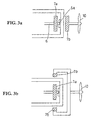
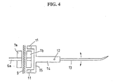
- two small magnets 11 are attached to a U-shaped member 15 with either one of their N-pole or S-pole being faced inward on the right and left sides of the second magnet 7b, the U-shaped member 15 extends to sandwich the second magnet 7b at the front end of the horizontal rod 14.
- the horizontal rod 14 is supported to horizontally and reciprocally move about a support shaft 12 located at the rear portion of the propeller 10.
- a caudal fin 13 is vertically attached to the rear end of the horizontal rod 14. Therefore, the right and left small magnets 11 alternatingly receive an attractive force and a repulsive force due to a change in the magnetic field produced by the rotation of the magnet 7b, and the caudal fin 13 accordingly oscillates to the right and left via the horizontal rod 14.
- the underwater toy proceeds while finely oscillating right and left to simulate a fish movement.
- the vertical output shaft 6b and a small pulley 16 are coupled together via a first magnet 7a and a second magnet 7b.
- the rotation of the small pulley 16 is reduced and is transmitted to a large pulley 18 via a rubber belt 17.
- a weight 20 is attached to the large pulley 18 via an arm 19 cantilevered to the lower surface thereof from the central direction. As the weight 20 slowly turns together with the large pulley 18, the entire center of gravity of the toy is displaced, whereby the fish-type underwater toy greatly shakes its body back and forth, and right and left, and, as a result, proceeds to describe a locus of motion which is twisting to a large extent.
- the weight 20 can also be utilized as means for converting the direction of the toy when it comes to a side surface or corner of the water tank or container.
- a space is formed between the solar panel 1 on the upper surface and the toy body 3, and a float 21 of a foamed styrol or the like is accommodated therein.
- the float 21 is adjusted in its volume so that the particular fish-type underwater toy is weighted in the water to slowly sink the float 21 and is positioned just over the center of gravity so that a horizontal attitude can be maintained.
- Reference numeral 22 denotes a wire that can touch the bottom of the tank, and the main body 3 swings in the water with the end thereof as a fulcrum emphasizing a feeling of floating.
- the underwater toy must have a specific gravity which is nearly 1.
- the water temperature may also be adjusted, an air lift may be utilized, an adjusting weight may be utilized, a suitable additive may be added to the water, or any other liquid may be mixed thereto.
- a head of the fish is simply a decorative feature.
- the junction portion to the main toy body 3 is a support which can freely rotate about a vertical shaft 23, and a mechanism for opening and closing the mouth is a horizontal support that can freely rotate. Therefore, they move following fine oscillations of the main toy body 3 to express a simulated living operation such as moving the neck and opening/closing the mouth while moving in a forward or reverse direction.
- Pectoral fins and dorsal fin are made of a thin rubber film which swings following the oscillation of the main body 3 or a change in the water stream in the container.
- the second magnet 7b and the drive shaft outside the container 8 are rotated by the motor 4, by the output shaft operably coupled thereto and by the first magnet 7a secured to the output shaft that are sealed in the container 8, making it possible to carry out the operation in the water without being affected by the water.
- the power source for the motor 4 need not necessarily be the solar panel but may be power cells. However, the cells must also be made waterproof or must be contained in the same container 8 as that of the motor 4.
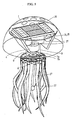
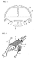
- FIG. 5 illustrates a case when the underwater toy is modeled after a jellyfish.
- reference numeral 1 denotes a solar panel which is a source of drive, and can be constituted in the same manner as the example described above, and includes those with their light-receiving surfaces facing upward relative to the main toy body 3 and those with their light-receiving surfaces facing downward in an inclined manner so as to receive light from the upper side and light from the lower side reflected by mirrors (not shown) provided on the bottom of the water tank.
- the five solar cells 1 are made waterproof by using transparent plastic plates which are vacuum-press-adhered from the front and back surfaces and include those horizontally attached to the main body with their light-receiving surfaces facing upward and those attached to both side surfaces of the main body with their light-receiving surfaces facing downward in an inclined manner.
- the solar cells are so arranged as to receive light from the upper side and light from the lower side reflected by the mirrors placed on the bottom of the water tank.
- the solar cells horizontally attached include large cells and small cells in combination, the large ones for powering and the small ones for the charging circuit.
- a charging circuit 24 and an intermittent operation circuit 25 are arranged on the motor 4 that is arranged at the center of the main toy body 3, and are so wired as to operate intermittently while light is being received as well as when no light is falling for a short period of time.
- a first doughnut-type magnet 7a having an N-pole and an S-pole on the same plane. They are contained and sealed in the container 8 which as a whole is made waterproof.
- a second doughnut-type magnet 7b is disposed facing the first magnet 7a via a separator wall 9 which is a side wall of the container 8, and a propeller 10 (drive means) secured thereto is so supported as to freely rotate.
- the above constitution When any surface of the solar panel 1 receives light from the sun or from other illumination sources, the above constitution generates electric power by which the motor 4 rotates thereby to rotate the first magnet 7a causing a change in the magnetic field. Therefore, the second magnet 7b rotates synchronizing therewith.
- the motor 4 turns and stops repetitively due to the intermittent operation circuit 25, which can include a timer circuit to turn the motor 4 on and off, and the jellyfish-type underwater toy repetitively operates to ascend, stop and sink.
- a space is formed between the solar panel 1 on the upper surface and the main toy body 3, and a float 21 of a foamed styrol or the like is accommodated therein.
- the float 21 is adjusted for its volume so that the jellyfish-type underwater toy slowly sinks, and is positioned just over the center of gravity so that a horizontal attitude can be maintained.
- an extension wire 22 that touches the bottom is protruding downward from the lower part of the main toy body 3.
- the end of the wire 22 touches the bottom of the water tank so that the main toy body 3 itself does not touch the bottom.
- the main body 3 swings in the water with the end of the wire 11 touching the bottom as a fulcrum member for emphasizing the feeling of floating.
- a transparent dome 26 constituting the head is modeled after the shape of a real jellyfish and is made of a transparent plastic material so it will not interrupt light from the upper side and has a plurality of water-drain holes perforated in the vertex portion thereof.
- the lower part of the transparent dome 26 is forming a fine radial skeleton, and a soft doughnut-like thin film 26a is covered thereon from the upper side so as to be deformed with a small force.
- a plurality of arms or tentacles 27 are made of a thin rubber film so as to swing depending upon a change in the water stream.
- This embodiment has functions of propulsion in both the horizontal and vertical directions.
- a very weak circulatory water flow or ascending or descending water stream may be established in the water tank by a pump as an environment in the water. Even when dead angles or zones of the source of light are expected, the optical underwater toy successively moves inside and outside the areas where it will be irradiated with light, and is therefore necessarily maintained and supplied with electric power.
- a skirt 28 is continuously fitted to the lower radial skeleton of the transparent dome 26, a plurality of small magnets 29 are attached to the inner peripheral edge portions of the skirt 28 and are arranged near the second magnet 7b. Then, the small magnets 29 altematingly receive an attractive force and a repulsive force due to a change in the magnetic field caused by the rotation of the magnet 7b, and the skirt 28 oscillates up and down. Then, the skeleton constituting the dome and the thin film pulsate to impart a more real feeling to the main toy body 3.
- the second magnet 7b and the drive means 10 on the outside of the container 8 are rotated by the motor 4, by the output shaft 6 operably coupled thereto and by the first magnet 7a secured to the output shaft 6 that are sealed in the container 8. Therefore, the operation is realized in the water without being affected by the water.
- Fig. 7 illustrates a case of when the underwater toy is modeled after a shrimp.
- the power source is a solar panel 1 having the same structure as the embodiment described above, and is disposed with its light-receiving surface facing upward relative to the main toy body 3 so as to receive light from the upper side.
- the underwater toy is so adjusted as to sink down to the bottom of the water.
- a motor 4 and reduction gears (crown gear 5a and spur gear 5b) are arranged at the center of the main toy body 3, and a first doughnut-type magnet 7a having an N-pole and an S-pole on the same plane is attached to the output shaft 6. They are contained and sealed in the container 8 which as a whole is made waterproof.
- a second doughnut-type magnet 7b is opposed to the above first magnet 7a via a separator wall 9 which is a side wall of the container 8, and a small pulley 30 is secured thereto.
- the rotation of the small pulley 30 is reduced and is transmitted to a large pulley 32 via a rubber belt 31.
- the large pulley 32 is fastened to a drive shaft 33 to which both ends are attached two resilient propulsion wires 34 at positions deviated by 180° from each other.
- Transparent balls 35 are attached to the ends of the wires 34.
- the above constitution When any surface of the solar panel 1 receives light from the sun or from an illumination, the above constitution generates electric power by which the motor 4 rotates thereby to simultaneously rotate the output shaft 6 and the first magnet 7a.
- the rotation of the first magnet 7a causes a change in the magnetic field and, hence, the second magnet 7b rotates synchronizing therewith.
- the rotational force is transmitted from the small pulley to the large pulley 32, and the drive shaft means 10 rotates.
- the two wires 34 alternate so as to operate to kick the bottom of the tank or the water, and the shrimp-type underwater toy operates to appear to jump intermittently.
- Simulated legs are made of a thin rubber film to swing following the oscillation of the main body 3 and any change in the water stream.
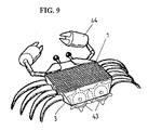
- Fig. 9 illustrates a case when the underwater toy is modeled after a crab.
- the power source is a solar panel 1 having the same structure as the one described above, and is disposed with its light-receiving surface facing upward relative to the main toy body 3 so as to receive light from the upper side.
- a circuit casing or the like is provided under the solar panel.
- the underwater toy is also adjusted as to sink down to the bottom of the water.
- a motor 4 and reduction gears (crown gear 5a and spur gear 5b) are arranged at the center of the main toy body 3, and a first doughnut-type magnet 7a having an N-pole and an S-pole on the same plane is attached to the output shaft 6. They are contained and sealed in the container 8 which as a whole is made waterproof.
- a second doughnut-type magnet 7b is opposed to the above first magnet 7a via a separator wall 9 which is a side wall of the container 8, and a small pulley 37 is secured thereto.
- the rotation of the small pulley 37 is reduced and is transmitted to a large pulley 39 via a rubber belt 38.
- the large pulley 39 is fastened to an end of one of drive shafts 40 provided at the right and left of the main toy body 3.
- Pulleys 41 are provided at the other ends of the two drive shafts 40, and a rubber belt 42 is stretched between the two pulleys 41.
- Rotary means such as prongs 43 having protuberances on the circumferences thereof are attached to the above other ends of the two drive shafts 40.
- Reference numeral 44 denotes a float for floating the side (front side) opposite to the rotary means 43 of the main toy body 3.
- the above constitution When any surface of the solar panel 1 receives light from the sun or from an illumination, the above constitution generates electric power by which the motor 4 rotates thereby to simultaneously rotate the output shaft 6 and the first magnet 7a.
- the rotation of the first magnet 7a causes a change in the magnetic field and, hence, the second magnet 7b rotates synchronizing therewith.
- the rotational force is transmitted from the small pulley 37 to the large pulley 39, and the drive shafts 40 rotate.
- the drive shafts 40 rotate, the rotation prongs 43 rotate, and the crab-type underwater toy moves to proceed intermittently.
- the motor 4 is so set to rotate forward and reverse at regular intervals, the underwater toy reciprocally moves toward the right and left.
- the legs are made of thin rubber films so as to swing following a change in the water stream.
- the above underwater toys are not necessarily limited to those of the above-mentioned types of fish, crab, shrimp and jellyfish.
- the underwater toy may, for example, be a submarine.
- each of these underwater toys could be remotely controlled with wireless receivers and remote controllers. Additionally, charging circuits and intermittent power circuits can also be provided in each underwater toy if desired.
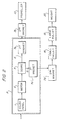
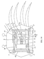
- FIG. 11 is a view schematically illustrating a system for accommodating the operation of the underwater toys.
- the aquarium system comprises a transparent container 45, a liquid 46 filled in the container 45, an illumination means for illuminating the interior of the container 45, and an underwater toy A equipped with a drive mechanism 48 that operates to swim in the container 45 as it is illuminated by the illumination means such as lamps 47.
- the container 45 may be a water tank.
- the liquid 46 may be water, or water to which another liquid is added, or even liquid other than water.
- the liquids may be combined together to adjust the specific gravity so that the underwater toy A does not float or sink in the liquid 46.
- a heater unit (not shown) can be used with temperature control to maintain a set temperature for the liquid to further adjust the buoyancy of the liquid.
- the illuminating means 47 may be an ordinary light for illumination by which the solar panel of the underwater toy A generates electricity.
- the underwater toy A is the one illustrated in Fig. 1, it may be equipped with any mechanism constituted by the operation mechanism 48 that is operated by the electric power generated by the solar panel, i.e., the one constituted by motor, reduction gears, propeller, rotary means, etc. as shown in Figs. 5, 7, 9, 17 and 18.
- the underwater toy A can be further controlled so as to stabilize its attitude, to float or to sink relying upon a balance between the propulsive force of the underwater toy A and the water stream.
- the water stream is not readily visible to the observer, and accordingly, supplements the driving force of the solar cells.
- two small magnets 61 are attached to a U-shaped member 65 with either one of their N-pole or S-pole being faced inward on the right and left sides of the second magnet 57b, the U-shaped member 65 so extending as to sandwich the second magnet 57b at the front end of the horizontal rod 64.
- the horizontal rod 64 is supported to horizontally and reciprocally move about a support shaft 62 located at the rear portion of the propeller 10.
- a caudal fin 62 is vertically attached to the rear end of the horizontal rod 64.
- the right and left small magnets 61 alternatingly receive an attractive force and a repulsive force due to a change in the magnetic field produced by the rotation of the magnet 57b, and the caudal fin 63 oscillates to the right and left via the horizontal rod 64.
- the underwater toy proceeds while finely oscillating right and left to simulate a swimming movement.
- Such an oscillating mode can be further realized by using an unbalanced propeller 3a or 3b as shown in Figs. 13(a) and 13(b).
- the fish-type underwater toy apparently swims in the water by utilizing, as the power source, the electric power generated by the solar panel 1.
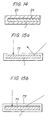
- the solar panel 1 generates electric power as it is irradiated with light from a source of light for illumination or from the sun, and is protected against the water by a protection layer of a transparent protecting material as shown in Fig. 14. Further, a transparent light reflection prevention layer is formed on the surface on where light is incident and the layer is made waterproof.
- the incident light is further refracted by the light reflection prevention layer 74 as shown in Fig. 15(b) and more light is converted into electricity.
- the transparent light reflection prevention layer 74 is formed on the inner bottom of a transparent plastic protection container 75 as shown in Fig. 16, the solar panel 1 is intimately adhered thereon and, then, a closure 76 of the protection container 75 is placed thereon from the upper side and is press-adhered in a vacuum.
- the solar panel 1 may be intimately sealed to be waterproof by any other method.
- the solar panel 1 is so arranged that light falls from the side of the light reflection prevention layer 74.
- the light reflection prevention layer 74 may be made of a material that prevents the reflection of light, such as highly transparent silicone, transparent resin or epoxy resin.
- the light reflection prevention layer 74 being formed on the surface of the solar panel 1 on where the light falls, the light is prevented from reflecting even when the light of an illumination apparatus or of the sun is falling from an inclined direction, and incident light is efficiently converted into electricity. It is therefore made possible to obtain a drive source sufficient for operating the underwater toy.
- the reflection prevention layer is formed on the incident surface of the solar panel. Therefore, the light is prevented from reflecting even when the light of the illumination apparatus or of the sun is falling from an inclined direction, and the incident light is efficiently converted into electricity. It is therefore made possible to obtain a power source sufficient for operating the underwater drive unit.
- Fig. 17 is a perspective view of another fish-type toy.
- reference numeral 101 denotes a plurality of solar cells
- 102 denotes a plurality of motors
- 103 denotes a charging circuit
- 104 denotes a remote control receiver circuit
- 105a and 105b denote doughnut-type magnets
- 106 denotes a plurality of propellers
- 109 denotes a caudal fin
- 110 denotes a float
- reference numeral 111 denotes a wire that touches the bottom.
- Ten solar cells 101 are made waterproof by using transparent plastic plates that are vacuum-press-adhered from the front and back surfaces include those which are horizontally attached to the main body with their light-receiving surfaces facing upward, those which are attached to both side surfaces of the main body with their light-receiving surfaces facing downward in an inclined manner, and those of a small size which are attached to both side surfaces of the main body with their light-receiving surfaces facing upward in an inclined manner.
- the solar calls are thus arranged to receive light from an upper direction and light from a lower side reflected by mirrors placed on the bottom of the water tank.
- the large solar cells are for powering and the small solar cells are for the charging circuit.
- Three motors 102 are arranged in order from the rear part of the main body, being laterally arranged facing backward, being vertically arranged facing downward, and being laterally arranged facing forward, respectively.
- a charging circuit 103 connected to small solar cells is arranged in the upper part of the motor at the rear portion, and a remote control receiver circuit 104 is arranged in the upper part of the motor at the front portion.
- the solar cells 101 are connected to the remote control receiver circuit 104 through the charging circuit 103, and are further wired to control the three motors 102. They are made waterproof inclusive of the wiring by a continuous container to thereby constitute a main body skeleton.
- the remote control receiver circuit 104 has a receiving portion 104a that protrudes beyond the main body.
- the remote operation of forward turn, reverse turn or stop can be executed for the three motors 102 according to a received signal.
- the doughnut-type magnet 105a having an N-pole and an S-pole on the same plane is secured to an end of the output shaft of each of the motors 102.
- the doughnut type magnet 105b is similarly placed facing the magnet 105a via a separator wall, so that the propeller 106 fastened thereto is allowed to freely rotate.
- the propeller 106 turns via the magnet 105b that synchronizes with a change in the magnetic field by the turn of the magnet 105a.
- the main body moves forward, backward, up, down, or turns.
- two small magnets 107 are secured to a U-shaped member with their single electrode of either N or S only being faced inward, the U-shaped member extending so as to sandwich the magnet 105b at the front ends of the horizontal rod 108.
- the horizontal rod 108 is freely supported so as to horizontally and reciprocally move about a support shaft located at a rear part of the propeller 106.
- a caudal fin 109 is vertically attached to the rear end of the horizontal rod.
- the right and left small magnets 107 Due to a change in the magnetic field by the turn of the magnet 105b, the right and left small magnets 107 alternatingly receive an attractive force and a repulsive force, and the caudal fin 109 oscillates right and left via the horizontal rod 108. Therefore, the main body moves forward or backward while finely oscillating right and left.
- a space is formed between the solar cells 101 on the upper surface and the main body, and a float 110 of a foamed styrol or the like is accommodated therein.
- the float 110 is adjusted for its volume so that the fish-type toy slowly sinks, and is positioned just over the center of gravity so that a horizontal attitude can be maintained.
- a wire 111 that touches the bottom is protruding downward from the lower part of the main body. When the main body no longer moves and sinks, the end of the wire touches the bottom of the water tank so that the main body itself does not touch the bottom. The main body swings in the water with the end of the wire 111 touching the bottom as a fulcrum emphasizing the feeling of floating.
- a head 112 of the fish is simply a modeling.
- the junction portion to the main body is a vertical support which can freely rotate, and a mechanism for opening and closing the mouth is a horizontal support that can freely rotate. Therefore, they move following fine oscillation of the main body expressing living operation such as moving the neck and opening/closing the mouth while moving forward or reverse.
- Pectoral fins 113 and dorsal fin 114 are made of a thin rubber film which swing following the oscillation of the main body or a change in the water stream.
- FIG. 18 is a perspective view of this fish-type toy.
- reference numeral 101 denotes solar cells
- 102 denotes a motor
- 105a and 105b denote doughnut-type magnets
- 106 denotes a propeller
- 109 denotes a caudal fin
- 110 denotes a float
- 111 denotes a wire that touches the bottom
- 120 denotes a reduction gear box
- 121 denotes a small pulley
- 123 denotes a large pulley
- reference numeral 124 denotes a weight.
- the three solar cells 101 are made waterproof by using transparent plastic plates which are vacuum-press-adhered from the front and back surfaces include one that is horizontally attached to the main body with its light-receiving surface facing upward, and those attached to both side surfaces of the main body with their light-receiving surfaces facing downward in an inclined manner.
- the solar cells 101 are so arranged as to receive light from the upper side and light from the lower side reflected by the mirrors placed on the bottom of the water tank.
- the motor 102 is arranged at the center of the main body, the reduction gear box 120 is arranged at a rear portion thereof, doughnut-type magnets 105a having N-poles and S-poles on the same plane are attached to the ends of the horizontal output shaft and to the vertical output shaft thereof, and are made waterproof by a continuous container to thereby constitute a main body skeleton.
- the motor rotates and the two output shafts rotate simultaneously.
- the doughnut type magnet 105b is similarly placed facing the magnet 105a via a separator wall, so that the propeller 106 fastened thereto and the small pulley 121 are allowed to freely rotate.
- the propeller 106 and the small pulley 121 turn simultaneously via the magnet 105b that synchronizes with a change in the magnetic field by the turn of the magnet 105a.
- the main body moves forward.
- two small magnets 107 are secured to a U-shaped member with their single electrode of either N or S only being faced inward, the U-shaped member extending so as to sandwich the magnet 105b at the front ends of the horizontal rod 108.
- the horizontal rod 108 is freely supported so as to horizontally and reciprocally move about a support shaft located at a rear part of the propeller 106.
- a caudal fin 109 is vertically attached to the rear end of the horizontal rod.
- the right and left small magnets 107 Due to a change in the magnetic field by the turn of the magnet 105b, the right and left small magnets 107 alternatingly receive an attractive force and a repulsive force, and the caudal fin 109 oscillates right and left via the horizontal rod 108. Therefore, the main body moves forward while finely oscillating right and left.
- the rotation of the small pulley 121 is reduced and transmitted to the large pulley 123 via a rubber belt 122.
- the large pulley 123 has an arm cantilevered to the lower surface thereof from the central direction, and the weight 124 is attached to an end of the arm. As the weight 124 slowly turns together with the large pulley 123, the entire center of gravity successively moves, whereby the fish-type toy greatly shakes its body back and forth, and right and left, and, as a result, proceeds describing a locus which is twisting to a large extent. This expresses a more complex and living behavior in addition to fine right-and-left oscillation.
- a space is formed between the solar cells 101 on the upper surface and the main body, and a float 110 of a foamed styrol or the like is accommodated therein.
- the float 110 is adjusted for its volume so that the fish-type toy slowly sinks, and is positioned just over the center of gravity so that a horizontal attitude can be maintained.
- a wire 111 that touches the bottom is protruding downward from the lower part of the main body. When the main body no longer moves and sinks, the end of the wire touches the bottom of the water tank so that the main body itself does not touch the bottom. The main body swings in the water with the end of the wire 111 touching the bottom as a fulcrum emphasizing the feeling of floating.
- a head 112 of the fish is simply a modeling.
- the junction portion to the main body is a vertical support which can freely rotate, and a mechanism for opening and closing the mouth is a horizontal support that can freely rotate. Therefore, they move following fine oscillation of the main body expressing living operation such as moving the neck and opening/closing the mouth while moving forward or reverse.
- Pectoral fins 113 and dorsal fin 114 are made of a thin rubber film which swing following the oscillation of the main body or a change in the water stream.
Landscapes
- Life Sciences & Earth Sciences (AREA)
- Environmental Sciences (AREA)
- Marine Sciences & Fisheries (AREA)
- Animal Husbandry (AREA)
- Biodiversity & Conservation Biology (AREA)
- Toys (AREA)
Applications Claiming Priority (6)
| Application Number | Priority Date | Filing Date | Title |
|---|---|---|---|
| JP2000071325 | 2000-03-14 | ||
| JP2000071326A JP3326153B2 (ja) | 2000-03-14 | 2000-03-14 | 水中用ソーラーパネル |
| JP2000071326 | 2000-03-14 | ||
| JP2000071325 | 2000-03-14 | ||
| JP2000073063A JP3183872B1 (ja) | 2000-03-14 | 2000-03-15 | 水中玩具及びその観賞システム |
| JP2000073063 | 2000-03-15 |
Publications (1)
| Publication Number | Publication Date |
|---|---|
| EP1134011A2 true EP1134011A2 (fr) | 2001-09-19 |
Family
ID=27342668
Family Applications (1)
| Application Number | Title | Priority Date | Filing Date |
|---|---|---|---|
| EP00120990A Withdrawn EP1134011A2 (fr) | 2000-03-14 | 2000-09-27 | Système d'aquarium avec jouets sous-marins robotisés |
Country Status (4)
| Country | Link |
|---|---|
| EP (1) | EP1134011A2 (fr) |
| KR (1) | KR20010091861A (fr) |
| CN (1) | CN1313201A (fr) |
| CA (1) | CA2320497A1 (fr) |
Cited By (17)
| Publication number | Priority date | Publication date | Assignee | Title |
|---|---|---|---|---|
| EP1530991A1 (fr) * | 2003-11-11 | 2005-05-18 | Evolve NPD Limited | Jouet magnetique |
| GB2415913A (en) * | 2004-07-10 | 2006-01-11 | Dimitri Rembisz | Underwater propulsion unit |
| EP1617922A4 (fr) * | 2003-04-29 | 2007-11-28 | Mattel Inc | Dispositif de jeu rempli de fluide |
| CN101391650B (zh) * | 2008-06-18 | 2010-09-15 | 哈尔滨工业大学 | 形状记忆合金丝驱动的仿生机器水母 |
| KR101094789B1 (ko) | 2009-08-07 | 2011-12-16 | 한국생산기술연구원 | 물고기형 로봇 및 그 유영 기법 |
| CN102795069A (zh) * | 2012-08-03 | 2012-11-28 | 南京航空航天大学 | 复合驱动的仿水母两栖机器人的运动方法 |
| CN102795068A (zh) * | 2012-08-03 | 2012-11-28 | 南京航空航天大学 | 复合驱动的仿水母两栖机器人 |
| WO2015059678A1 (fr) * | 2013-10-25 | 2015-04-30 | Mathew Peter Mowbray | Procédé de charge sans contact de jouet aquatique, jouet et réservoir associé |
| US9934613B2 (en) | 2014-04-29 | 2018-04-03 | The Florida International University Board Of Trustees | Systems for controlling a movable object |
| CN111137421A (zh) * | 2020-01-19 | 2020-05-12 | 浙江理工大学 | 一种基于电机驱动的仿生皮皮虾水下划行装置 |
| CN112201136A (zh) * | 2020-09-21 | 2021-01-08 | 合肥磐石自动化科技有限公司 | 一种仿生水母足及应用该仿生水母足的机械水母 |
| CN114468720A (zh) * | 2022-03-09 | 2022-05-13 | 河北有鸣绒毛制品有限公司 | 一种会摆尾巴的茶宠鱼 |
| CN115486409A (zh) * | 2022-10-26 | 2022-12-20 | 西安石油大学 | 一种仿生海扁虫鱼缸清理器及其控制方法 |
| US11557414B2 (en) | 2020-04-23 | 2023-01-17 | Idea Vault Holdings Inc | Magnetically interconnectable block structures and methods for making the same |
| RU2797610C1 (ru) * | 2022-12-28 | 2023-06-07 | Федеральное государственное бюджетное образовательное учреждение высшего образования "Поволжский государственный технологический университет" | Аквариум с рыбками-роботами |
| USD1048229S1 (en) | 2020-01-14 | 2024-10-22 | Idea Vault Holdings, Inc. | Toy piece |
| TWI889487B (zh) * | 2024-08-12 | 2025-07-01 | 先鋒材料科技股份有限公司 | 水下裝置 |
Families Citing this family (12)
| Publication number | Priority date | Publication date | Assignee | Title |
|---|---|---|---|---|
| KR101107083B1 (ko) * | 2009-11-24 | 2012-01-20 | 한국기계연구원 | 수중로봇용 동력전달장치 |
| KR101107084B1 (ko) * | 2009-11-24 | 2012-01-20 | 한국기계연구원 | 수중로봇용 축 실링장치 |
| KR101284430B1 (ko) * | 2011-05-16 | 2013-07-09 | 울산대학교 산학협력단 | 로봇 물고기 및 이를 포함하는 인공 수족관 |
| CN102411867A (zh) * | 2011-11-01 | 2012-04-11 | 翁元霆 | 太阳能潜水艇 |
| TWI482651B (zh) * | 2012-05-21 | 2015-05-01 | Univ Chaoyang Technology | 智慧型供能之電動魚水族系統 |
| TWI482652B (zh) * | 2012-08-01 | 2015-05-01 | Univ Nat Pingtung Sci & Tech | 光能追蹤供電飛魚系統 |
| KR101467288B1 (ko) * | 2013-11-13 | 2014-12-12 | 연세대학교 산학협력단 | 어항을 위한 수중 이동로봇 |
| WO2019006987A1 (fr) * | 2017-07-04 | 2019-01-10 | 江苏共井集团有限公司 | Sous-marin semi-submersible de divertissement familial |
| CN108552071B (zh) * | 2018-03-30 | 2024-01-26 | 河南牧业经济学院 | 一种猪用福利食槽 |
| CN110588934B (zh) * | 2019-10-15 | 2024-01-30 | 上海海洋大学 | 一种水下柔性仿生鱿鱼 |
| CN112868742B (zh) * | 2021-01-26 | 2022-12-27 | 余世兵 | 一种基于食品加工的干虾甩米装置 |
| CN119873941B (zh) * | 2025-02-25 | 2025-10-28 | 武汉理工大学 | 基于微气泡吸附的海洋微塑料收集装置 |
-
2000
- 2000-09-22 CA CA002320497A patent/CA2320497A1/fr not_active Abandoned
- 2000-09-27 EP EP00120990A patent/EP1134011A2/fr not_active Withdrawn
- 2000-09-28 KR KR1020000057125A patent/KR20010091861A/ko not_active Withdrawn
- 2000-09-28 CN CN00134420A patent/CN1313201A/zh active Pending
Non-Patent Citations (1)
| Title |
|---|
| None |
Cited By (24)
| Publication number | Priority date | Publication date | Assignee | Title |
|---|---|---|---|---|
| EP1617922A4 (fr) * | 2003-04-29 | 2007-11-28 | Mattel Inc | Dispositif de jeu rempli de fluide |
| EP1530991A1 (fr) * | 2003-11-11 | 2005-05-18 | Evolve NPD Limited | Jouet magnetique |
| US7297042B2 (en) | 2003-11-11 | 2007-11-20 | Evolve Npd Limited | Magnetic toy |
| GB2415913A (en) * | 2004-07-10 | 2006-01-11 | Dimitri Rembisz | Underwater propulsion unit |
| GB2415913B (en) * | 2004-07-10 | 2008-07-09 | Dimitri Rembisz | Pressure Compensated Underwater Propulsion Unit |
| CN101391650B (zh) * | 2008-06-18 | 2010-09-15 | 哈尔滨工业大学 | 形状记忆合金丝驱动的仿生机器水母 |
| KR101094789B1 (ko) | 2009-08-07 | 2011-12-16 | 한국생산기술연구원 | 물고기형 로봇 및 그 유영 기법 |
| CN102795069A (zh) * | 2012-08-03 | 2012-11-28 | 南京航空航天大学 | 复合驱动的仿水母两栖机器人的运动方法 |
| CN102795068A (zh) * | 2012-08-03 | 2012-11-28 | 南京航空航天大学 | 复合驱动的仿水母两栖机器人 |
| CN102795068B (zh) * | 2012-08-03 | 2014-08-13 | 南京航空航天大学 | 复合驱动的仿水母两栖机器人 |
| CN102795069B (zh) * | 2012-08-03 | 2014-08-13 | 南京航空航天大学 | 复合驱动的仿水母两栖机器人的运动方法 |
| WO2015059678A1 (fr) * | 2013-10-25 | 2015-04-30 | Mathew Peter Mowbray | Procédé de charge sans contact de jouet aquatique, jouet et réservoir associé |
| US10086308B2 (en) | 2013-10-25 | 2018-10-02 | Mathew Peter Mowbray | Method of contactless charging of aquatic toy, toy and tank therefor |
| US9934613B2 (en) | 2014-04-29 | 2018-04-03 | The Florida International University Board Of Trustees | Systems for controlling a movable object |
| USD1048229S1 (en) | 2020-01-14 | 2024-10-22 | Idea Vault Holdings, Inc. | Toy piece |
| USD1103294S1 (en) | 2020-01-14 | 2025-11-25 | Idea Vault Holdings, Inc. | Toy piece |
| CN111137421A (zh) * | 2020-01-19 | 2020-05-12 | 浙江理工大学 | 一种基于电机驱动的仿生皮皮虾水下划行装置 |
| US11557414B2 (en) | 2020-04-23 | 2023-01-17 | Idea Vault Holdings Inc | Magnetically interconnectable block structures and methods for making the same |
| CN112201136A (zh) * | 2020-09-21 | 2021-01-08 | 合肥磐石自动化科技有限公司 | 一种仿生水母足及应用该仿生水母足的机械水母 |
| CN112201136B (zh) * | 2020-09-21 | 2022-08-19 | 合肥磐石智能科技股份有限公司 | 一种仿生水母足及应用该仿生水母足的机械水母 |
| CN114468720A (zh) * | 2022-03-09 | 2022-05-13 | 河北有鸣绒毛制品有限公司 | 一种会摆尾巴的茶宠鱼 |
| CN115486409A (zh) * | 2022-10-26 | 2022-12-20 | 西安石油大学 | 一种仿生海扁虫鱼缸清理器及其控制方法 |
| RU2797610C1 (ru) * | 2022-12-28 | 2023-06-07 | Федеральное государственное бюджетное образовательное учреждение высшего образования "Поволжский государственный технологический университет" | Аквариум с рыбками-роботами |
| TWI889487B (zh) * | 2024-08-12 | 2025-07-01 | 先鋒材料科技股份有限公司 | 水下裝置 |
Also Published As
| Publication number | Publication date |
|---|---|
| KR20010091861A (ko) | 2001-10-23 |
| CA2320497A1 (fr) | 2001-09-14 |
| CN1313201A (zh) | 2001-09-19 |
Similar Documents
| Publication | Publication Date | Title |
|---|---|---|
| CA2320497A1 (fr) | Systeme d'aquarium avec jouets sous-marins robotises | |
| US5301444A (en) | Swimming toy fish | |
| KR101576117B1 (ko) | 생체 모방 물고기의 구동 및 제어 방법과 생체 모방 물고기 | |
| CN100519331C (zh) | 智能机器海豚 | |
| CN109760811B (zh) | 一种基于海洋馆观赏型仿生鱿鱼 | |
| US5463826A (en) | Swimming toy fish aquarium having multiple toy fish and different magnet positions | |
| JP3318557B2 (ja) | クラゲ型水中遊泳玩具 | |
| KR20090024646A (ko) | 전자석을 이용한 인형 구동 장치 | |
| WO2015056224A1 (fr) | Procede d'entrainement et de commande d'un jouet biomimetique, et jouet biomimetique | |
| US5685096A (en) | Swimming toy fish aquarium having magnetic drive system for magnetically driving the toy fish in the aquarium | |
| CN108545163A (zh) | 一种仿水母运动的水下机器人 | |
| CN209905022U (zh) | 一种基于海洋馆观赏型仿生鱿鱼 | |
| CN114671000A (zh) | 一种基于正弦摆动波动鳍结构的仿生魔鬼鱼机器人 | |
| JP3183872B1 (ja) | 水中玩具及びその観賞システム | |
| JP3326153B2 (ja) | 水中用ソーラーパネル | |
| EP0627248B1 (fr) | Aquarium de poissons jouets nageant ayant plusieurs poissons jouets et différentes positions d'aimants | |
| EP0584944B1 (fr) | Poisson-jouet nageant | |
| JP3183873B1 (ja) | 水中玩具の観賞システム | |
| KR20010107487A (ko) | 유영체 감상 시스템 | |
| CN221024123U (zh) | 一种基于线翎电鳗的多运动模态仿生机器鱼 | |
| JP3072354U (ja) | 水中玩具 | |
| JP2001070667A (ja) | 光水中玩具 | |
| CN205832620U (zh) | 一种水中玩具的驱动和转向装置 | |
| JP2002119772A (ja) | 水中玩具 | |
| CN2652477Y (zh) | 浮力磁动玩具 |
Legal Events
| Date | Code | Title | Description |
|---|---|---|---|
| PUAI | Public reference made under article 153(3) epc to a published international application that has entered the european phase |
Free format text: ORIGINAL CODE: 0009012 |
|
| AK | Designated contracting states |
Kind code of ref document: A2 Designated state(s): AT BE CH CY DE DK ES FI FR GB GR IE IT LI LU MC NL PT SE |
|
| AX | Request for extension of the european patent |
Free format text: AL;LT;LV;MK;RO;SI |
|
| STAA | Information on the status of an ep patent application or granted ep patent |
Free format text: STATUS: THE APPLICATION IS DEEMED TO BE WITHDRAWN |
|
| 18D | Application deemed to be withdrawn |
Effective date: 20030401 |