EP1134129A2 - Dispositif retenant l'arceau d'un système de protection par arceau - Google Patents
Dispositif retenant l'arceau d'un système de protection par arceau Download PDFInfo
- Publication number
- EP1134129A2 EP1134129A2 EP01102559A EP01102559A EP1134129A2 EP 1134129 A2 EP1134129 A2 EP 1134129A2 EP 01102559 A EP01102559 A EP 01102559A EP 01102559 A EP01102559 A EP 01102559A EP 1134129 A2 EP1134129 A2 EP 1134129A2
- Authority
- EP
- European Patent Office
- Prior art keywords
- holding
- holding device
- fork
- bolt
- rollover
- Prior art date
- Legal status (The legal status is an assumption and is not a legal conclusion. Google has not performed a legal analysis and makes no representation as to the accuracy of the status listed.)
- Granted
Links
Images


Classifications
-
- B—PERFORMING OPERATIONS; TRANSPORTING
- B60—VEHICLES IN GENERAL
- B60R—VEHICLES, VEHICLE FITTINGS, OR VEHICLE PARTS, NOT OTHERWISE PROVIDED FOR
- B60R21/00—Arrangements or fittings on vehicles for protecting or preventing injuries to occupants or pedestrians in case of accidents or other traffic risks
- B60R21/02—Occupant safety arrangements or fittings, e.g. crash pads
- B60R21/13—Roll-over protection
- B60R2021/132—Roll bars for convertible vehicles
- B60R2021/134—Roll bars for convertible vehicles movable from a retracted to a protection position
- B60R2021/135—Roll bars for convertible vehicles movable from a retracted to a protection position automatically during an accident
Definitions
- the invention relates to a holding device for the rollover body a rollover protection system for motor vehicles, the one on the rollover body attached retaining member with a retaining bolt which is releasable mechanical active connection with a trigger element of a sensor-controlled Release system stands.
- Rollover protection systems such as those found in convertibles or sports cars are used, typically have a guided roll body, especially roll bar, on, which in the normal state against the Preload force of a drive compression spring by a holding device in one lower rest position is maintained, and sensor-controlled in the event of a rollover Loosen the holding device in an upper, protective and locked there Position can be brought.
- the holding device typically has an am Rolling element fastened holding member, which in detachable mechanical Active connection with a trigger element on a sensor-controlled Trigger system, which is typically by a trigger magnet so-called crash magnets or by a pyrotechnic trigger is formed.
- the holding member After a release, when the rollover is brought back into the Rest position, be it manually or by means of a comfort drive, the holding member automatically returnable to the holding starting position, the holding position his.
- Holding devices of the aforementioned type are numerous Construction variants became known.
- the well-known system can feed in at the trigger system Rigidity not all manufacturing tolerances and misalignments, at least not without the occurrence of transverse forces.
- DE 197 50 457 A 1 is a holding device with a bell-shaped retaining member, into which balls snap, become known. This system requires a time-consuming adjustment to ensure that the holding member automatically returns to the holding position after triggering is feasible.
- the simulation of extreme Installation situations i.e. with a very strong diagonal bracing of the Roll bar, shown that the balls despite careful adjustment of the Retaining member, not always automatically when pushing back Snap the roll bar into the holding position. The same applies to the Holding device from DE 37 32 562 C1.
- EP 0 761 505 A1 shows a holding device for a rollover body a rigid support rod as a holding member, which has a cone tip and the is provided with a circumferential groove for engaging locking balls in Cross bores of a holding element connected to the release system are arranged radially movable.
- This holding device can not all Manufacturing and assembly tolerances safely and without cross loads compensate.
- the invention is based on the object, the one mentioned Training device so that misalignment and Manufacturing tolerances when retracting the roll body and thus the Retaining member in the release member in a simple manner effective without Tensions can be compensated.
- the holding member as a holding fork is formed, which is constructed from an elastically yielding material, and rigidly connected to the roll body, and in the fork legs the retaining bolt is held.
- the elastically yielding material consists of a corresponding one Metal, preferably spring steel, bronze or brass or alternatively made of a corresponding elastic elastic plastic.
- the design of the holding fork can be according to an embodiment of the Invention be made such that the holding fork is an extruded part, or a Injection molded part with holes in the fork legs for storing the Retaining bolt.
- the holding fork can also be formed from a sheet metal part with a first embodiment of the invention such that the holding fork from a single-shell sheet metal part is formed, which alternately in the fork leg each have a semicircular shape as a bearing for the retaining bolt has, or with a second embodiment of the invention such that the Holding fork is formed in two shells from a sheet metal part, and in both Fork legs each two opposite semicircular Characteristics are formed as bearing points for the retaining bolt.
- the holding member As an alternative to the design of the holding member as a holding fork Holding device according to another development of the invention formed that the holding member has a bell-shaped receiving body has holes on two opposite areas with it molded hollow bearing pin for the retaining bolt, and the an extension at the head for rigid attachment to the rollover body at least one thin web, which elastic deflection of the Allows receiving body has.
- This bell-shaped casing of the retaining bolt prevents dirt from reaching the interface to the Release system that could prevent tripping.
- a particularly good flexibility of the bell-shaped receiving body is given when the extension two thin 90 ° to each other Has web areas.
- a first one constructive design is that at the top of the extension two fastening tabs are formed for fastening with a clamp, and the clamp can be connected to the rollover body.
- a second constructive design is that on the Top of the extension a connecting element for a positive Connection with the roll body is formed.
- the bell-shaped receiving body with its Bearing pin and the extension made of plastic and is preferably a Injection molded part, which is a particularly economical production of the holding member enables.
- Every release system which is a hook-shaped release link for active intervention with the retaining bolt is applicable in principle.
- Special advantages in terms of trigger security are achieved when the trigger system a release magnet in connection with a double lever system than in Has active engagement with the retaining pin standing release member.
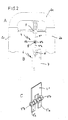
- Fig. 1 shows a schematic representation with three views, the Figure parts A, B and C, a first embodiment of the invention Holding device for the rollover body of a rollover protection system for Motor vehicles.
- Rollover protection systems of this type as used in particular in convertibles or Sports cars used typically have a guided tour Rollover body, here in the form of a roll bar 1, which in the present Example is composed of three tubes 2 a, 2 b and 2 c.
- a guided tour Rollover body here in the form of a roll bar 1
- the base leg of the roll bar 1 is essentially a curved tube 2 a, which at its ends with two leg tubes 2 b, 2 c through Welding or other suitable types of connection is rigidly connected.
- the Leg tubes 2 a, 2 b are in vehicle-fixed (not shown) Standpipes guided.
- the holding device typically has an am Roll bar attached retaining member 4, which is detachable mechanical Active connection with a trigger element 5 on a sensor-controlled Trigger system 6, which is typically a trigger magnet 7, the so-called crash magnets.
- 1 C is a Release system with a release magnet in connection with a Double lever system shown as a trigger member 5, which by DE 197 50th 693 A 1 has become known.
- the holding member 4 is formed in the example of FIG. 1 as a holding fork 4 'and carries in the fork legs 4 'a a retaining bolt 8, which is there with usual constructive methods.
- the holding fork 4 ' is one Fork holder extension 9 and a clamp 10 with the base leg 2 a of Roll bar 1 rigidly connected, the connection between the fork bracket 9 and the clamp 10 by means of a screw connection 11.
- a rollover protection system of the type shown in FIG. 1 is shown, for example, in of DE 43 42 400 A1 cited at the beginning, which also describes the others Components of a rollover protection system shows. Since it is in the case of the invention solely on the design of the holding device is in Fig. 1 and in the other figures only this holding device is shown explicitly. With regard to the other components, the relevant state of the Technology referred.
- the rollover protection system shown in FIG. 1 just an example of possible embodiments in which the holding device according to the invention can be used.
- Holding fork 4 'formed elastically yielding which is typically due to the Structure of the holding fork from a resilient material, e.g. Spring steel or another metallic metal material, such as spring bronze or brass or an elastically yielding plastic.
- the holding member 4 is designed as a solid holding fork 4 ', for example in the form of a plastic injection molded part, the retaining bolt 8 stored in solid fork legs 4 'a in holes in these legs is.
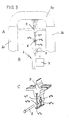
- FIG. 2 and 3 show an embodiment of the holding fork 4, the Sheet metal parts is constructed and serves as an insert in a plastic injection molded part, these embodiments being otherwise identical to those according to FIG. 1 to match.
- FIG. 2 shows three parts A, B and C in one piece and single-shell made from a sheet of spring steel or the like Holding fork 4 ", the mutual semicircular forms 4" b Has the holding bolt 8 for locking in the trigger system 6 has.
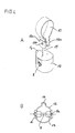
- FIG 3 alternatively shows one in three figure parts A, B and C. in one piece and two shells from a sheet metal part made of spring steel or the like manufactured fork 4 "', two in each leg opposite semicircular shapes 4 '' 'b for receiving the Holding bolt 8 has.
- the holding forks 4 ", 4" 'according to FIGS. 2 and 3 preferably consist of Spring steel sheet, or another metallic sheet with resilient Properties such as bronze or brass.
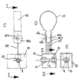
- FIGS. 4 and 5 show two embodiments of the invention Holding member, which encased a bell-shaped on all sides, open at the bottom and in cross section (Fig. 4 D, 5 D) fork-shaped receiving body 12 for the Holding bolt 8, which is in active engagement with the sensor-controlled triggering system 6 can be brought according to FIGS. 1-3.
- the bell shape of the receiving body 12 ensures that no dirt the interface between the retaining bolt 8 and the trigger member 5 in the system can penetrate, which could prevent a deliberate triggering. Further allows the bell-shaped receiving body 12 a structurally favorable Storage of the retaining bolt 8.
- the bell-shaped receiving body 12 has in both embodiments one molded on the inside on two opposite sides Bearing pin 13 for receiving the retaining bolt 8. This is in the assembled State with his head 8 a on the outer surface of the receiving body 12, whereas its other end has a groove-shaped groove 8 b, the one usual snap ring 14 picks up.
- the bell-shaped receiving body 12 with its Journal 13 each made of plastic and is preferably a Injection molded part.
- the molded bearing journals 13 are preferably, as in FIG. 4 E can be seen, rounded at the bottom, in order to insert the holding member in the trigger system 16 to facilitate a stop against too far Insert into the release system to form, and in the locked state To keep the retaining bolt 8 relatively horizontal. You can also add one yourself have insertion bevels extending below (not shown).
- the bell-shaped receiving body 12 at least one section with a thin web 15, the elastic bending of the receiving body allows to hold the retaining bolt 8 securely in the locking lever 5 of the Trigger system 6 (Fig. 1) to introduce.
- the webs 15 are preferably on the Bell of the receiving body 12 is formed towards the end of its attachment.
- the receiving body 12 on End of the thin web 15 two mounting tabs 15 a with holes 15 b on, by means of which it can be fastened to the clamp 10, which in turn, on Crossbar 2 a of the roll bar is attachable, analogous to the version Fig. 1.
- the receiving body 12 has on one side of its jacket a shape 16 for the necessary pivoting range of the holding lever of Trigger system 5.
- the mounting tabs 15 a des Receiving body 12 recessed recesses for positive reception the leg of the clamp 10 to misassembly or accidental To prevent twisting (commuting).
- Guide lugs 18 support the retraction of the retaining bolt 8 in the Release system 6. These guide lugs can also be used in the execution Fig. 4 may be provided.
- Figures 1-3 show the deployed condition of the roll bar
- 5E shows the active engagement of the retaining bolt 8 with the release system 6.
- the trigger system preferably consists of a crash magnet 7 and one of which can be operated double lever system 5 as a trigger for the Active engagement with the retaining bolt 8.
- the crash magnet 7 is actuated the lever 5 locking the locking pin 8 (due to pivoting of an upstream lever) is pivoted counterclockwise and releases the retaining bolt 8 and thus the roll bar 1, which due to the Drive spring 3 snaps into its upper support position.
Landscapes
- Engineering & Computer Science (AREA)
- Mechanical Engineering (AREA)
- Clamps And Clips (AREA)
- Aiming, Guidance, Guns With A Light Source, Armor, Camouflage, And Targets (AREA)
- Registering, Tensioning, Guiding Webs, And Rollers Therefor (AREA)
Applications Claiming Priority (2)
| Application Number | Priority Date | Filing Date | Title |
|---|---|---|---|
| DE10012573A DE10012573C1 (de) | 2000-03-15 | 2000-03-15 | Haltevorrichtung für den Überrollkörper eines Überrollschutzsystems |
| DE10012573 | 2000-03-15 |
Publications (3)
| Publication Number | Publication Date |
|---|---|
| EP1134129A2 true EP1134129A2 (fr) | 2001-09-19 |
| EP1134129A3 EP1134129A3 (fr) | 2004-07-21 |
| EP1134129B1 EP1134129B1 (fr) | 2006-01-18 |
Family
ID=7634787
Family Applications (1)
| Application Number | Title | Priority Date | Filing Date |
|---|---|---|---|
| EP20010102559 Expired - Lifetime EP1134129B1 (fr) | 2000-03-15 | 2001-02-06 | Dispositif retenant l'arceau d'un système de protection par arceau |
Country Status (3)
| Country | Link |
|---|---|
| EP (1) | EP1134129B1 (fr) |
| DE (2) | DE10012573C1 (fr) |
| ES (1) | ES2254269T3 (fr) |
Cited By (1)
| Publication number | Priority date | Publication date | Assignee | Title |
|---|---|---|---|---|
| DE102005013376A1 (de) * | 2005-03-23 | 2006-09-28 | Bayerische Motoren Werke Ag | Überrollschutzsystem |
Families Citing this family (4)
| Publication number | Priority date | Publication date | Assignee | Title |
|---|---|---|---|---|
| DE10342488B4 (de) * | 2003-09-10 | 2006-04-27 | Ise Innomotive Systems Europe Gmbh | Überrollschutzsystem für Kraftfahrzeuge mit einem ausfahrbaren Überrollkörper |
| DE10353867B3 (de) * | 2003-11-18 | 2005-02-03 | Ise Innomotive Systems Europe Gmbh | Überrollschutzsystem für Kraftfahrzeuge mit einem ausfahrbaren Überrollkörper |
| DE102004015808B3 (de) * | 2004-03-31 | 2005-03-10 | Ise Gmbh | Überrollschutzsystem für Kraftfahrzeuge mit einem ausfahrbaren Überrollkörper |
| CN114132283B (zh) * | 2021-11-12 | 2022-11-01 | 合肥正浩机械科技有限公司 | 一种车辆倾翻自动扶正系统 |
Citations (8)
| Publication number | Priority date | Publication date | Assignee | Title |
|---|---|---|---|---|
| DE3732562C1 (de) | 1987-09-26 | 1988-11-24 | Daimler Benz Ag | Antriebsvorrichtung fuer einen UEberrollbuegel fuer Kraftwagen |
| DE4314538A1 (de) | 1993-05-03 | 1994-11-10 | Bayerische Motoren Werke Ag | Überrollschutz-Vorrichtung für ein Kraftfahrzeug |
| DE4342400A1 (de) | 1993-08-03 | 1995-02-09 | Teves Gmbh Alfred | Überrollbügeleinrichtung mit Innenführung und Außenführung |
| EP0729867A1 (fr) | 1993-05-03 | 1996-09-04 | Bayerische Motoren Werke Aktiengesellschaft, Patentabteilung AJ-3 | Dispositif à arceau de sécurité pour véhicule automobile |
| EP0760314A1 (fr) | 1995-08-28 | 1997-03-05 | Bayerische Motoren Werke Aktiengesellschaft, Patentabteilung AJ-3 | Liaison pour élémentde sécurité de véhicule déplaçableen position opérationnelle, en particulier pour arceau de sécurité |
| EP0761505A1 (fr) | 1995-08-14 | 1997-03-12 | Bayerische Motoren Werke Aktiengesellschaft, Patentabteilung AJ-3 | Dispositif d'accouplement déployable pour un élément de sécurité d'un véhicule, notamment pour un arceau de sécurité |
| DE19750457A1 (de) | 1997-11-14 | 1999-06-02 | Itt Mfg Enterprises Inc | Ausfahrbarer Überrollbügel für Kraftfahrzeuge |
| DE19949944C1 (de) | 1999-10-16 | 2000-12-28 | Ise Gmbh | Haltevorrichtung für den Überrollkörper eines Überollschutzsystems |
Family Cites Families (1)
| Publication number | Priority date | Publication date | Assignee | Title |
|---|---|---|---|---|
| DE19604423A1 (de) * | 1996-02-07 | 1997-08-14 | Bayerische Motoren Werke Ag | Überrollschutz für ein Kraftfahrzeug |
-
2000
- 2000-03-15 DE DE10012573A patent/DE10012573C1/de not_active Expired - Fee Related
-
2001
- 2001-02-06 EP EP20010102559 patent/EP1134129B1/fr not_active Expired - Lifetime
- 2001-02-06 ES ES01102559T patent/ES2254269T3/es not_active Expired - Lifetime
- 2001-02-06 DE DE50108714T patent/DE50108714D1/de not_active Expired - Fee Related
Patent Citations (8)
| Publication number | Priority date | Publication date | Assignee | Title |
|---|---|---|---|---|
| DE3732562C1 (de) | 1987-09-26 | 1988-11-24 | Daimler Benz Ag | Antriebsvorrichtung fuer einen UEberrollbuegel fuer Kraftwagen |
| DE4314538A1 (de) | 1993-05-03 | 1994-11-10 | Bayerische Motoren Werke Ag | Überrollschutz-Vorrichtung für ein Kraftfahrzeug |
| EP0729867A1 (fr) | 1993-05-03 | 1996-09-04 | Bayerische Motoren Werke Aktiengesellschaft, Patentabteilung AJ-3 | Dispositif à arceau de sécurité pour véhicule automobile |
| DE4342400A1 (de) | 1993-08-03 | 1995-02-09 | Teves Gmbh Alfred | Überrollbügeleinrichtung mit Innenführung und Außenführung |
| EP0761505A1 (fr) | 1995-08-14 | 1997-03-12 | Bayerische Motoren Werke Aktiengesellschaft, Patentabteilung AJ-3 | Dispositif d'accouplement déployable pour un élément de sécurité d'un véhicule, notamment pour un arceau de sécurité |
| EP0760314A1 (fr) | 1995-08-28 | 1997-03-05 | Bayerische Motoren Werke Aktiengesellschaft, Patentabteilung AJ-3 | Liaison pour élémentde sécurité de véhicule déplaçableen position opérationnelle, en particulier pour arceau de sécurité |
| DE19750457A1 (de) | 1997-11-14 | 1999-06-02 | Itt Mfg Enterprises Inc | Ausfahrbarer Überrollbügel für Kraftfahrzeuge |
| DE19949944C1 (de) | 1999-10-16 | 2000-12-28 | Ise Gmbh | Haltevorrichtung für den Überrollkörper eines Überollschutzsystems |
Cited By (2)
| Publication number | Priority date | Publication date | Assignee | Title |
|---|---|---|---|---|
| DE102005013376A1 (de) * | 2005-03-23 | 2006-09-28 | Bayerische Motoren Werke Ag | Überrollschutzsystem |
| EP1705073A3 (fr) * | 2005-03-23 | 2006-10-04 | Bayerische Motorenwerke Aktiengesellschaft | Système d'arceau de sécurité |
Also Published As
| Publication number | Publication date |
|---|---|
| EP1134129B1 (fr) | 2006-01-18 |
| EP1134129A3 (fr) | 2004-07-21 |
| DE50108714D1 (de) | 2006-04-06 |
| ES2254269T3 (es) | 2006-06-16 |
| DE10012573C1 (de) | 2001-03-01 |
Similar Documents
| Publication | Publication Date | Title |
|---|---|---|
| DE102006021884B3 (de) | Längseinsteller für einen Fahrzeugsitz | |
| DE102011056844B4 (de) | Viergelenk integrierter Fußgängerschutz | |
| EP1182098A2 (fr) | Système d'arceau de sécurité | |
| WO2007115524A2 (fr) | Raccordement de tiges de piston | |
| EP1202878B1 (fr) | Ensemble pour automobile | |
| EP0636798A2 (fr) | Elément de fixation rotatif | |
| DE60003370T2 (de) | Abscherbare Gleitbefestigung für ein Kunststoffteil auf einem Tragelement | |
| DE102019116492A1 (de) | Dachhaltegriff | |
| EP3287325B1 (fr) | Véhicule automobile et dispositif de fixation pour un véhicule automobile | |
| DE102007006835A1 (de) | Aktuierungsmittel für eine crash-aktive Kopfstütze | |
| DE10012573C1 (de) | Haltevorrichtung für den Überrollkörper eines Überrollschutzsystems | |
| DE102008032324A1 (de) | Blockiervorrichtung für einen Betätigungszug, insbesondere Bowdenzug, einer Schließvorrichtung eines beweglichen Karosserieteils eines Fahrzeugs | |
| EP2216205B1 (fr) | Galerie pour véhicules automobiles | |
| WO2015078957A1 (fr) | Revêtement de sac gonflable et procédé pour sa fabrication | |
| DE102018005316A1 (de) | Kopfstütze | |
| DE102010014394A1 (de) | Längseinsteller-Entriegelungsvorrichtung für einen Fahrzeugsitz | |
| DE19949944C1 (de) | Haltevorrichtung für den Überrollkörper eines Überollschutzsystems | |
| EP1134130A2 (fr) | Dispositif d'arceau avec cassette fixée sur le véhicule | |
| DE19840642A1 (de) | Befestigungselement für einen Betätigungszug | |
| DE102012209058A1 (de) | Scheibenwischvorrichtung | |
| DE102018208196A1 (de) | Pufferelement für eine Frontklappe oder Heckklappe eines Kraftfahrzeuges sowie Anordnung eines solchen Pufferelements an einem Karosserieelement eines Kraftfahrzeuges | |
| DE10010765C1 (de) | Haltevorrichtung für den Überrollkörper eines Überrollschutzsystems | |
| DE102018205809B4 (de) | Trägerelement zum Befestigen eines Innenverkleidungsteils an einem Bauteil eines Fahrzeugs. | |
| DE102007031009B4 (de) | Verfahren zur Herstellung eines Pedalwerks für ein Fahrzeug | |
| DE102008025871A1 (de) | Überrollbügelanordnung |
Legal Events
| Date | Code | Title | Description |
|---|---|---|---|
| PUAI | Public reference made under article 153(3) epc to a published international application that has entered the european phase |
Free format text: ORIGINAL CODE: 0009012 |
|
| AK | Designated contracting states |
Kind code of ref document: A2 Designated state(s): AT BE CH CY DE DK ES FI FR GB GR IE IT LI LU MC NL PT SE TR |
|
| AX | Request for extension of the european patent |
Free format text: AL;LT;LV;MK;RO;SI |
|
| PUAL | Search report despatched |
Free format text: ORIGINAL CODE: 0009013 |
|
| AK | Designated contracting states |
Kind code of ref document: A3 Designated state(s): AT BE CH CY DE DK ES FI FR GB GR IE IT LI LU MC NL PT SE TR |
|
| AX | Request for extension of the european patent |
Extension state: AL LT LV MK RO SI |
|
| 17P | Request for examination filed |
Effective date: 20040828 |
|
| 17Q | First examination report despatched |
Effective date: 20050303 |
|
| AKX | Designation fees paid |
Designated state(s): DE ES FR GB IT SE |
|
| GRAP | Despatch of communication of intention to grant a patent |
Free format text: ORIGINAL CODE: EPIDOSNIGR1 |
|
| GRAS | Grant fee paid |
Free format text: ORIGINAL CODE: EPIDOSNIGR3 |
|
| GRAA | (expected) grant |
Free format text: ORIGINAL CODE: 0009210 |
|
| AK | Designated contracting states |
Kind code of ref document: B1 Designated state(s): DE ES FR GB IT SE |
|
| REG | Reference to a national code |
Ref country code: GB Ref legal event code: FG4D Free format text: NOT ENGLISH |
|
| REF | Corresponds to: |
Ref document number: 50108714 Country of ref document: DE Date of ref document: 20060406 Kind code of ref document: P |
|
| GBT | Gb: translation of ep patent filed (gb section 77(6)(a)/1977) |
Effective date: 20060320 |
|
| REG | Reference to a national code |
Ref country code: SE Ref legal event code: TRGR |
|
| REG | Reference to a national code |
Ref country code: ES Ref legal event code: FG2A Ref document number: 2254269 Country of ref document: ES Kind code of ref document: T3 |
|
| ET | Fr: translation filed | ||
| PLBE | No opposition filed within time limit |
Free format text: ORIGINAL CODE: 0009261 |
|
| STAA | Information on the status of an ep patent application or granted ep patent |
Free format text: STATUS: NO OPPOSITION FILED WITHIN TIME LIMIT |
|
| 26N | No opposition filed |
Effective date: 20061019 |
|
| PGFP | Annual fee paid to national office [announced via postgrant information from national office to epo] |
Ref country code: SE Payment date: 20080225 Year of fee payment: 8 |
|
| PGFP | Annual fee paid to national office [announced via postgrant information from national office to epo] |
Ref country code: ES Payment date: 20090225 Year of fee payment: 9 |
|
| PGFP | Annual fee paid to national office [announced via postgrant information from national office to epo] |
Ref country code: DE Payment date: 20090219 Year of fee payment: 9 |
|
| PGFP | Annual fee paid to national office [announced via postgrant information from national office to epo] |
Ref country code: GB Payment date: 20090223 Year of fee payment: 9 |
|
| PGFP | Annual fee paid to national office [announced via postgrant information from national office to epo] |
Ref country code: IT Payment date: 20090226 Year of fee payment: 9 |
|
| EUG | Se: european patent has lapsed | ||
| PGFP | Annual fee paid to national office [announced via postgrant information from national office to epo] |
Ref country code: FR Payment date: 20090217 Year of fee payment: 9 |
|
| GBPC | Gb: european patent ceased through non-payment of renewal fee |
Effective date: 20100206 |
|
| REG | Reference to a national code |
Ref country code: FR Ref legal event code: ST Effective date: 20101029 |
|
| PG25 | Lapsed in a contracting state [announced via postgrant information from national office to epo] |
Ref country code: FR Free format text: LAPSE BECAUSE OF NON-PAYMENT OF DUE FEES Effective date: 20100301 |
|
| PG25 | Lapsed in a contracting state [announced via postgrant information from national office to epo] |
Ref country code: DE Free format text: LAPSE BECAUSE OF NON-PAYMENT OF DUE FEES Effective date: 20100901 |
|
| PG25 | Lapsed in a contracting state [announced via postgrant information from national office to epo] |
Ref country code: IT Free format text: LAPSE BECAUSE OF NON-PAYMENT OF DUE FEES Effective date: 20100206 Ref country code: GB Free format text: LAPSE BECAUSE OF NON-PAYMENT OF DUE FEES Effective date: 20100206 |
|
| REG | Reference to a national code |
Ref country code: ES Ref legal event code: FD2A Effective date: 20110401 |
|
| PG25 | Lapsed in a contracting state [announced via postgrant information from national office to epo] |
Ref country code: SE Free format text: LAPSE BECAUSE OF NON-PAYMENT OF DUE FEES Effective date: 20090207 |
|
| PG25 | Lapsed in a contracting state [announced via postgrant information from national office to epo] |
Ref country code: ES Free format text: LAPSE BECAUSE OF NON-PAYMENT OF DUE FEES Effective date: 20110322 |
|
| PG25 | Lapsed in a contracting state [announced via postgrant information from national office to epo] |
Ref country code: ES Free format text: LAPSE BECAUSE OF NON-PAYMENT OF DUE FEES Effective date: 20100207 |
|
| REG | Reference to a national code |
Ref country code: DE Ref legal event code: R082 Ref document number: 50108714 Country of ref document: DE Representative=s name: KALKOFF & PARTNER PATENTANWAELTE, DE |
|
| REG | Reference to a national code |
Ref country code: DE Ref legal event code: R082 Ref document number: 50108714 Country of ref document: DE Representative=s name: KALKOFF & PARTNER PATENTANWAELTE, DE Effective date: 20130812 Ref country code: DE Ref legal event code: R081 Ref document number: 50108714 Country of ref document: DE Owner name: METALSA AUTOMOTIVE GMBH, DE Free format text: FORMER OWNER: ISE AUTOMOTIVE GMBH, 51702 BERGNEUSTADT, DE Effective date: 20130812 |