EP1134171A2 - Durchlaufregal für Behälter in Kastenform - Google Patents
Durchlaufregal für Behälter in Kastenform Download PDFInfo
- Publication number
- EP1134171A2 EP1134171A2 EP01106709A EP01106709A EP1134171A2 EP 1134171 A2 EP1134171 A2 EP 1134171A2 EP 01106709 A EP01106709 A EP 01106709A EP 01106709 A EP01106709 A EP 01106709A EP 1134171 A2 EP1134171 A2 EP 1134171A2
- Authority
- EP
- European Patent Office
- Prior art keywords
- rail
- flow rack
- rack according
- folded
- functional position
- Prior art date
- Legal status (The legal status is an assumption and is not a legal conclusion. Google has not performed a legal analysis and makes no representation as to the accuracy of the status listed.)
- Granted
Links
Images



Classifications
-
- B—PERFORMING OPERATIONS; TRANSPORTING
- B65—CONVEYING; PACKING; STORING; HANDLING THIN OR FILAMENTARY MATERIAL
- B65G—TRANSPORT OR STORAGE DEVICES, e.g. CONVEYORS FOR LOADING OR TIPPING, SHOP CONVEYOR SYSTEMS OR PNEUMATIC TUBE CONVEYORS
- B65G1/00—Storing articles, individually or in orderly arrangement, in warehouses or magazines
- B65G1/02—Storage devices
- B65G1/04—Storage devices mechanical
- B65G1/06—Storage devices mechanical with means for presenting articles for removal at predetermined position or level
- B65G1/08—Storage devices mechanical with means for presenting articles for removal at predetermined position or level the articles being fed by gravity
Definitions
- the invention relates to a flow rack for containers in box shape according to the Preamble of claim 1.
- Such a flow rack known from DE 195 48 595 has separating strips which are laterally adjustable independently of the roller bars.
- the support level of the roller strips is slightly lower than that of the separating strips. You can use it to set the channel width the dividing strips are set so that they have a lateral guide for a container certain width. If the known flow rack is set up so that several small containers are guided, is a high number of separating strips intended. With a subsequent adaptation of the flow rack to wide containers some of these dividers must be removed and the remaining ones Separation strips can be adapted to the width of the new container. In practice, this leads to the problem that the separating strips removed are partly relocated and not can be found more. In addition, there is a subsequent adjustment of the flow rack on containers of smaller size, time-consuming, since the dividing strips are attached to the suitable places must be inserted and determined.
- the invention has for its object a structurally simple means Flow rack to create the most diverse containers in no time Design and size is customizable.
- the rails can be adapted Different containers folded into the functional or fold-down position as required become. It is not necessary to dismantle the rails.
- the rails can each can also be folded from the functional to the folding position if required there is still a container with a guide groove in the bottom in the corresponding channel of the Flow rack.
- the rail is in the functional position lockable. This ensures that the rail does not fold down when a Container is improperly inserted in the flow rack.
- the lateral distance between the central axes is the rails a multiple of 33 mm, preferably 99 mm. This makes it possible different KLT containers according to DIN 30820 in their longitudinal or transverse grooves to lead. It is also possible to attach the flow rack to a container in the shortest possible time with smooth bottom with and without stacking edge.
- the rail can therefore both can be used as a separating strip and as a guide rail. The adjustment can can also be carried out by untrained or non-specialist personnel.
- the rail is very long, it is advantageous to use the rail in the middle area at least one other attached to a middle frame connector To connect the swivel bracket to prevent the rail from bending.
- the rail is in the functional position in the fold-down position is folded in the direction of the removal side.
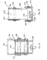
- a flow frame 18 for a flow rack is shown, the two at a distance has mutually arranged parallel frame side parts 28, 30, each on a side support frame (not shown) of a flow rack are attached.
- the Frame side parts 28, 30 are at their front end by a front, a stop forming frame connector 32 and at its rear end by a rear Frame connector 33 interconnected, which are shown in Figs. 2 and 3.
- the inclination of the frame side parts 28, 30 can be adjusted as desired.
- the pass plane of the pass frame 18 is from several to the lateral Support frame parallel roller strips 42 formed with one end to the front frame tie 32 and with its other end to the rear frame tie 33 for example by a plug connection, screwing or welding are attached.
- each two adjacent roller strips Rails 38a to 38h arranged with a U-shaped cross section open at the bottom.
- the Rails 38b, d, e, f are in a functional position in which their top side is 39 is located above the support plane of the roller strips 42 and runs parallel to it.
- the rails 38a, c, g, h are folded into a folding position in which they are below the Support level of the roller strips 42 lie.
- the rail 38b and the Frame side part 28 a lateral guide for a smooth container 44 without a stacking edge formed under which the folded rail 38a is located.
- the rail 38b forms also together with the rail 38d folded into the functional position Guide for a container 46 with a smooth bottom and stacking edge.
- the rail 38d and the rails 38f form a lateral guide for a container 48 with a stacking rim and a central longitudinal groove 52, in which the also folded into the functional position Rail 38e engages.
- a container 50 with smooth Bottom and stack edge through the rail 38f folded into the functional position and through the right frame side part 30 out.
- the rails folded into the folded position 38g and 38h are located below the bottom surface of the container 50.
- the distance between the individual rails 38a to 38h is selected so that the distance between the central axes of two 38 38 mm adjacent rails folded in the functional position or a multiple of 33mm. This distance is especially for KLT containers according to DIN 30820 suitable. With these containers, the rails 38a to h can be in their functional position remain, engaging in the grooves, on the bottom of the KLT container and on the Sides of the stack edge rest, which ensures excellent guidance is.
- the front frame connector 32 and the rear frame connector 33 each have a leg 54 or 56.
- the legs 54, 56 are arranged in one plane and face each other.
- a pivot bracket 58 is screwed, which is shown in more detail in FIGS. 4 and 5.
- the swivel bracket 58 has an upwardly open U-shaped cross section with two legs 62, 64 of the same design, which are joined at their lower ends by a web 66 are interconnected.
- the web 66 has an end longitudinal recess 68 and a rear longitudinal recess 70.
- the front swivel bracket 58 is by means of a fastening screw 72 passing through the front longitudinal recess 68 connected to the leg 54 of the front frame connector 32.
- the rear one Swivel bracket 58 is by means of a through the rear longitudinal recess 70 Fastening screw 74 on the leg 56 of the rear frame connector 33 connected.
- Each leg 62, 64 of the swivel brackets 58 has on the end face a lower horizontal section 76, which over an inclined ramp 78 merges into a higher horizontal section 80.
- the locking recess 84 will limited to the rear by a stop 86.
- level section 76 has a circular bearing opening 88 in each leg 62, 64 educated.
- an axis 90 is in the bearing openings 88 attached, which passes through an opening 91 which in one end of a pivot lever 92 is provided, which is arranged between the legs 62, 64.
- an elongated hole 94 is provided, through which a pin or axis 96 passes, which or in elongated holes 98 engages in the two vertical sides 99 of the rail 38 in the lower Corner areas of the rail 38 are provided, the vertical sides 99 outside the legs 62, 64 lie.
- FIGS. 7, 8 and 9 differs from that 2 and 3 by the type of pivot bearing of the rail 38th
- the swivel brackets 58 there is a horizontal one instead of the circular opening 88 Slot opening 91 is provided through which the pin 90 passes.
- Pins 90, 96 are arranged by a guide sleeve 100 arranged between the legs 62, 64 surrounded, whose diameter is such that the pins 96 when folding the Engage rail 38 in the functional position in the locking recesses 84.
- the pivot brackets 110 also have one U-shaped cross-section open at the top with two legs 114 of identical design, 116, which are connected to one another at their lower end by a web 118.
- the pivot bracket 110 has a lower end face horizontal front section 120 which is perpendicular to a higher one horizontal section 122 merges.
- Below section 122 is at the section height 120 a circular bearing opening 124 is formed in each leg 114, 116.
- Recess 126 and 128 In the upper area of the front and rear ends of the rail 38 is one Recess 126 and 128 provided. Is below the recess 126 or 128 each have a circular opening 130, 132 in the vertical legs 99 of the rail 38 trained.
- a bearing block 134 made of injection molded plastic pivoted.
- the bearing block 134 is in the folded position shown in FIG. 11 with its lower longitudinal side on the web 118 of the swivel bracket 110.
- a through opening 136 is formed, which is connected to the circular bearing openings 124 in the legs 114, 116 is aligned.
- An axle pin 138 goes through the Bearing openings 124 and the through openings 136 therethrough.
- An axle pin 137 goes through the Slot opening 139 and the circular openings 130, 132 through.
- the bearing block 134 has one on its front end side in the folded-down position (FIG. 11) lower vertical section 140, which extends approximately to the level of the horizontal Section 120 of the pivot bracket 110 extends.
- To the vertical section 140 adjoins a short, forwardly extending, horizontal section 142 which via an inclined section 143 with the horizontal upper longitudinal side 144 communicates.
- the rail 38 is very long, it is advantageous to have the rail 38 in the middle region with at least one other attached to a middle frame connector 150 To connect pivot bracket 152 to deflect the rail 38 prevent, as shown in Fig. 13.
- the swivel bracket 152 is like that Swivel bracket 110 of the third embodiment shown in FIGS. 10 and 11 educated.
- a bearing block 152 is the same as the bearing blocks 134 with the Swivel bracket 152 connected. Instead of the chamfer 143, the bearing block a flat end face 156 on which the web 146 rests in the functional position.
Landscapes
- Engineering & Computer Science (AREA)
- Mechanical Engineering (AREA)
- Warehouses Or Storage Devices (AREA)
- Rigid Containers With Two Or More Constituent Elements (AREA)
- Chutes (AREA)
Abstract
Description
- Fig. 1
- eine Querschnittsansicht eines geraden Durchlaufrahmens eines Durchlaufregals;
- Fig. 2
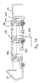
- eine geschnittene Seitenansicht einer ersten Ausführungsform eines Durchlaufrahmens mit einer Schiene in Funktionsstellung;
- Fig. 3
- eine geschnittene Seitenansicht des Durchlaufrahmens von Fig. 2 mit der Schiene in Abklappstellung;
- Fig. 4
- eine Seitenansicht einer Schwenkhalterung der Schiene von Fig. 3;
- Fig. 5
- eine Stirnansicht der Schwenkhalterung von Fig. 4;
- Fig. 6
- einen Schwenkhebel;
- Fig. 7
- eine geschnittene Seitenansicht einer zweiten Ausführungsform eines Durchlaufrahmens mit einer Schiene in Funktionsstellung;
- Fig. 8
- eine geschnittene Seitenansicht des Durchlaufrahmens von Fig. 7 mit der Schiene in Abklappstellung;
- Fig. 9
- eine Querschnittsansicht der Schwenklagerung der Schiene von Fig. 7;
- Fig. 10
- eine geschnittene Seitenansicht einer dritten Ausführungsform eines Durchlaufrahmens mit einer Schiene in Funktionsstellung;
- Fig. 11
- eine geschnittene Seitenansicht des Durchlaufrahmens von Fig. 10 mit der Schiene in Abklappstellung;
- Fig. 12
- eine Stirnansicht der Schwenklagerung der Schiene von Fig. 10.
- Fig. 13
- eine geschnittene Seitenansicht einer vierten Ausführungsform eines Durchlaufrahmens mit einer Schiene in Funktionsstellung;
Claims (10)
- Durchlaufregal für Behälter in Kastenform mit wenigstens einer horizontalen oder zur Entnahmeseite hin nach unten geneigten Auflageeinrichtung für die Behälter, die mehrere in Längsrichtung im wesentliche parallele, in einer Ebene angeordnete Rollenleisten (42) umfaßt, wobei wenigstens eine im wesentlichen parallel zu den Rollenleisten (42) angeordnete Schiene (38) vorgesehen ist,
dadurch gekennzeichnet, daß
die Schiene (38) aus einer Funktionsstellung, in der sie sich wenigstens teilweise über die Auflageebene (AE) der Rollenleisten (42) erstreckt, in eine Abklappstellung bewegbar ist, in der sie sich unterhalb der Auflageebene (AE) der Rollenleisten (42) befindet. - Durchlaufregal nach Anspruch 1, dadurch gekennzeichnet, daß die Schiene (38) in ihrer Längsrichtung klappbar ist.
- Durchlaufregal nach Anspruch 2, dadurch gekennzeichnet, daß die Schiene (38) an ihrem vorderen und hinteren Ende mit einem Ende eines Schwenkhebels (92) schwenkbar verbunden ist, der mit seinem anderen Ende an einer Schwenkhalterung (58) angelenkt ist.
- Durchlaufregal nach Anspruch 2, dadurch gekennzeichnet, daßdie Schiene (38) einen nach unten offenen U-förmigen Querschnitt mit zwei vertikalen Schenkel (99) hat,im Bereich des vorderen und hinteren Endes der Schiene (38) eine Führungshülse (100) zwischen den Schenkeln (99) angeordnet ist,ein erster Stift (96) durch die Schenkel (99) und die jeweilige Führungshülse (100) und ein zweiter Stift (90) durch eine Schwenkhalterung (58) und die Führungshülse (100) hindurchgeht.
- Durchlaufregal nach Anspruch 2, dadurch gekennzeichnet, daß
wenigstens das hintere, einlaufseitige Ende der Schiene (38) über einen Lagerblock (134) an einer Schwenkhalterung (110) gelagert ist, der eine Anlaufschräge (143) bildet, die in der Funktionsstellung in die Oberseite (146) der Schiene (38) übergeht. - Durchlaufregal nach einem der vorhergehenden Ansprüche, dadurch gekennzeichnet, daß die Schiene (38) in der Funktionsstellung verrastbar ist.
- Durchlaufregal nach einem der vorhergehenden Ansprüche, dadurch gekennzeichnet, daß der seitliche Abstand der Mittelachsen der Schienen (38) ein Vielfaches von 33 mm, vorzugsweise 99 mm beträgt, wenn sich die Schienen (38) in ihrer Funktionsstellung befinden.
- Durchlaufregal nach einem der Ansprüche 2 bis 7, dadurch gekennzeichnet, daß die Schiene im mittleren Bereich mit wenigstens eine weiteren Schwenkhalterung verbunden ist.
- Durchlaufregal nach einem der Ansprüche 1 bis 7, dadurch gekennzeichnet, daß die Schiene (38) aus der Funktionsstellung in die Abklappstellung in Richtung der Entnahmeseite geklappt wird.
- Durchlaufregal nach einem der Ansprüche 1 bis 7, dadurch gekennzeichnet, daß die Schiene (38) aus der Abklappstellung in die Funktonsstellung in Richtung der Entnahmeseite geklappt wird.
Applications Claiming Priority (2)
| Application Number | Priority Date | Filing Date | Title |
|---|---|---|---|
| DE20004931U | 2000-03-17 | ||
| DE20004931U DE20004931U1 (de) | 1999-06-23 | 2000-03-17 | Durchlaufregal für Behälter in Kastenform |
Publications (3)
| Publication Number | Publication Date |
|---|---|
| EP1134171A2 true EP1134171A2 (de) | 2001-09-19 |
| EP1134171A3 EP1134171A3 (de) | 2003-05-07 |
| EP1134171B1 EP1134171B1 (de) | 2004-12-01 |
Family
ID=7938896
Family Applications (1)
| Application Number | Title | Priority Date | Filing Date |
|---|---|---|---|
| EP01106709A Expired - Lifetime EP1134171B1 (de) | 2000-03-17 | 2001-03-16 | Durchlaufregal für Behälter in Kastenform |
Country Status (3)
| Country | Link |
|---|---|
| EP (1) | EP1134171B1 (de) |
| AT (1) | ATE283812T1 (de) |
| ES (1) | ES2234721T3 (de) |
Families Citing this family (1)
| Publication number | Priority date | Publication date | Assignee | Title |
|---|---|---|---|---|
| DE102008001972A1 (de) | 2008-05-26 | 2009-12-03 | Bito-Lagertechnik Bittmann Gmbh | Befestigungselement für eine Rollenleiste und Durchlaufregal |
Citations (1)
| Publication number | Priority date | Publication date | Assignee | Title |
|---|---|---|---|---|
| DE19548595A1 (de) | 1995-12-23 | 1997-06-26 | Krieg Gmbh E | Verfahren und Vorrichtung zum Behandeln von Wärmetauschern großer innerer Oberfläche |
Family Cites Families (1)
| Publication number | Priority date | Publication date | Assignee | Title |
|---|---|---|---|---|
| DE29910977U1 (de) * | 1999-06-23 | 1999-09-30 | Bito-Lagertechnik Bittmann GmbH, 55590 Meisenheim | Durchlaufregal für Behälter in Kastenform |
-
2001
- 2001-03-16 ES ES01106709T patent/ES2234721T3/es not_active Expired - Lifetime
- 2001-03-16 AT AT01106709T patent/ATE283812T1/de not_active IP Right Cessation
- 2001-03-16 EP EP01106709A patent/EP1134171B1/de not_active Expired - Lifetime
Patent Citations (1)
| Publication number | Priority date | Publication date | Assignee | Title |
|---|---|---|---|---|
| DE19548595A1 (de) | 1995-12-23 | 1997-06-26 | Krieg Gmbh E | Verfahren und Vorrichtung zum Behandeln von Wärmetauschern großer innerer Oberfläche |
Also Published As
| Publication number | Publication date |
|---|---|
| ATE283812T1 (de) | 2004-12-15 |
| EP1134171A3 (de) | 2003-05-07 |
| EP1134171B1 (de) | 2004-12-01 |
| ES2234721T3 (es) | 2005-07-01 |
Similar Documents
| Publication | Publication Date | Title |
|---|---|---|
| EP3094568B1 (de) | Behälter für den transport von waren und vorrichtung zur unterteilung eines solchen behälters | |
| DE69510578T2 (de) | Stapelbare und ineinandersetzbare Behälter | |
| EP0389802B1 (de) | Teilbarer Behälter, insbesondere Flaschenkasten | |
| EP0334348A2 (de) | Lager- und/oder Transportkasten | |
| WO2013052975A1 (de) | Einrichtung zum lagern von utensilien | |
| DE3205795A1 (de) | Vorrichtung zum haltern von platinen gedruckter schaltungen | |
| DE3301159A1 (de) | In drei ebenen wahlweise uebereinander und ineinander stapelbare container | |
| DE9300431U1 (de) | Rutschregal | |
| DE102019111950B4 (de) | Stapelbare Lagereinheit und Stapel aus Lagereinheiten | |
| DE3709190A1 (de) | Stapelfaehiger, kastenfoermiger behaelter | |
| EP2500291A1 (de) | Klappbarer Transport- und Lagerbehälter | |
| DE4335544C2 (de) | Transport- und Lagerpalette für Baugerüst-Stellrahmen | |
| DE20004931U1 (de) | Durchlaufregal für Behälter in Kastenform | |
| EP1134171B1 (de) | Durchlaufregal für Behälter in Kastenform | |
| DE3919379A1 (de) | Transporteinrichtung | |
| DE19548959C2 (de) | Durchlaufregal mit Trennleiste | |
| DE3419910C2 (de) | ||
| DE9404056U1 (de) | Stapelbarer Transportbehälter | |
| EP0792606A2 (de) | Regal | |
| DE9303527U1 (de) | Durchlaufregal, insbesondere für Kommissionierzwecke | |
| DE9216776U1 (de) | Palette aus Wellpappe | |
| EP0675045A1 (de) | Stapelbarer Transportbehälter | |
| EP1266371A1 (de) | Vorrichtung zur halterung von wendetafeln oder dergleichen | |
| DE102023114522A1 (de) | Maschinengestell für eine Vorrichtung zur Bereitstellung von Verpackungspolstermaterial, sowie Vorrichtung zur Bereitstellung von Verpackungspolstermaterial mit einem solchen Maschinengestell | |
| DE9210342U1 (de) | Kunststoffkiste mit Aufnahmefläche für ein entnehmbares Etikett |
Legal Events
| Date | Code | Title | Description |
|---|---|---|---|
| PUAI | Public reference made under article 153(3) epc to a published international application that has entered the european phase |
Free format text: ORIGINAL CODE: 0009012 |
|
| AK | Designated contracting states |
Kind code of ref document: A2 Designated state(s): AT BE CH CY DE DK ES FI FR GB GR IE IT LI LU MC NL PT SE TR |
|
| AX | Request for extension of the european patent |
Free format text: AL;LT;LV;MK;RO;SI |
|
| PUAL | Search report despatched |
Free format text: ORIGINAL CODE: 0009013 |
|
| AK | Designated contracting states |
Designated state(s): AT BE CH CY DE DK ES FI FR GB GR IE IT LI LU MC NL PT SE TR |
|
| AX | Request for extension of the european patent |
Extension state: AL LT LV MK RO SI |
|
| 17P | Request for examination filed |
Effective date: 20030515 |
|
| 17Q | First examination report despatched |
Effective date: 20030724 |
|
| AKX | Designation fees paid |
Designated state(s): AT BE CH CY DE DK ES FI FR GB GR IE IT LI LU MC NL PT SE TR |
|
| GRAP | Despatch of communication of intention to grant a patent |
Free format text: ORIGINAL CODE: EPIDOSNIGR1 |
|
| GRAS | Grant fee paid |
Free format text: ORIGINAL CODE: EPIDOSNIGR3 |
|
| GRAA | (expected) grant |
Free format text: ORIGINAL CODE: 0009210 |
|
| AK | Designated contracting states |
Kind code of ref document: B1 Designated state(s): AT BE CH CY DE DK ES FI FR GB GR IE IT LI LU MC NL PT SE TR |
|
| PG25 | Lapsed in a contracting state [announced via postgrant information from national office to epo] |
Ref country code: TR Free format text: LAPSE BECAUSE OF FAILURE TO SUBMIT A TRANSLATION OF THE DESCRIPTION OR TO PAY THE FEE WITHIN THE PRESCRIBED TIME-LIMIT Effective date: 20041201 Ref country code: IE Free format text: LAPSE BECAUSE OF FAILURE TO SUBMIT A TRANSLATION OF THE DESCRIPTION OR TO PAY THE FEE WITHIN THE PRESCRIBED TIME-LIMIT Effective date: 20041201 Ref country code: FI Free format text: LAPSE BECAUSE OF FAILURE TO SUBMIT A TRANSLATION OF THE DESCRIPTION OR TO PAY THE FEE WITHIN THE PRESCRIBED TIME-LIMIT Effective date: 20041201 |
|
| REG | Reference to a national code |
Ref country code: GB Ref legal event code: FG4D Free format text: NOT ENGLISH |
|
| REG | Reference to a national code |
Ref country code: CH Ref legal event code: EP |
|
| REG | Reference to a national code |
Ref country code: IE Ref legal event code: FG4D Free format text: GERMAN |
|
| REF | Corresponds to: |
Ref document number: 50104645 Country of ref document: DE Date of ref document: 20050105 Kind code of ref document: P |
|
| PG25 | Lapsed in a contracting state [announced via postgrant information from national office to epo] |
Ref country code: SE Free format text: LAPSE BECAUSE OF FAILURE TO SUBMIT A TRANSLATION OF THE DESCRIPTION OR TO PAY THE FEE WITHIN THE PRESCRIBED TIME-LIMIT Effective date: 20050301 Ref country code: GR Free format text: LAPSE BECAUSE OF FAILURE TO SUBMIT A TRANSLATION OF THE DESCRIPTION OR TO PAY THE FEE WITHIN THE PRESCRIBED TIME-LIMIT Effective date: 20050301 Ref country code: DK Free format text: LAPSE BECAUSE OF FAILURE TO SUBMIT A TRANSLATION OF THE DESCRIPTION OR TO PAY THE FEE WITHIN THE PRESCRIBED TIME-LIMIT Effective date: 20050301 |
|
| PG25 | Lapsed in a contracting state [announced via postgrant information from national office to epo] |
Ref country code: LU Free format text: LAPSE BECAUSE OF NON-PAYMENT OF DUE FEES Effective date: 20050316 Ref country code: AT Free format text: LAPSE BECAUSE OF NON-PAYMENT OF DUE FEES Effective date: 20050316 Ref country code: CY Free format text: LAPSE BECAUSE OF FAILURE TO SUBMIT A TRANSLATION OF THE DESCRIPTION OR TO PAY THE FEE WITHIN THE PRESCRIBED TIME-LIMIT Effective date: 20050316 |
|
| PG25 | Lapsed in a contracting state [announced via postgrant information from national office to epo] |
Ref country code: MC Free format text: LAPSE BECAUSE OF NON-PAYMENT OF DUE FEES Effective date: 20050331 Ref country code: LI Free format text: LAPSE BECAUSE OF NON-PAYMENT OF DUE FEES Effective date: 20050331 Ref country code: CH Free format text: LAPSE BECAUSE OF NON-PAYMENT OF DUE FEES Effective date: 20050331 |
|
| GBT | Gb: translation of ep patent filed (gb section 77(6)(a)/1977) |
Effective date: 20050329 |
|
| REG | Reference to a national code |
Ref country code: ES Ref legal event code: FG2A Ref document number: 2234721 Country of ref document: ES Kind code of ref document: T3 |
|
| REG | Reference to a national code |
Ref country code: IE Ref legal event code: FD4D |
|
| ET | Fr: translation filed | ||
| PG25 | Lapsed in a contracting state [announced via postgrant information from national office to epo] |
Ref country code: DE Free format text: LAPSE BECAUSE OF NON-PAYMENT OF DUE FEES Effective date: 20051001 |
|
| PLBE | No opposition filed within time limit |
Free format text: ORIGINAL CODE: 0009261 |
|
| STAA | Information on the status of an ep patent application or granted ep patent |
Free format text: STATUS: NO OPPOSITION FILED WITHIN TIME LIMIT |
|
| REG | Reference to a national code |
Ref country code: CH Ref legal event code: PL |
|
| 26N | No opposition filed |
Effective date: 20050902 |
|
| PG25 | Lapsed in a contracting state [announced via postgrant information from national office to epo] |
Ref country code: PT Free format text: LAPSE BECAUSE OF NON-PAYMENT OF DUE FEES Effective date: 20050501 |
|
| PGFP | Annual fee paid to national office [announced via postgrant information from national office to epo] |
Ref country code: FR Payment date: 20120403 Year of fee payment: 12 |
|
| PGFP | Annual fee paid to national office [announced via postgrant information from national office to epo] |
Ref country code: GB Payment date: 20120322 Year of fee payment: 12 Ref country code: BE Payment date: 20120329 Year of fee payment: 12 |
|
| PGFP | Annual fee paid to national office [announced via postgrant information from national office to epo] |
Ref country code: NL Payment date: 20120327 Year of fee payment: 12 |
|
| PGFP | Annual fee paid to national office [announced via postgrant information from national office to epo] |
Ref country code: IT Payment date: 20120328 Year of fee payment: 12 |
|
| PGFP | Annual fee paid to national office [announced via postgrant information from national office to epo] |
Ref country code: ES Payment date: 20120316 Year of fee payment: 12 |
|
| BERE | Be: lapsed |
Owner name: *BITO-LAGERTECHNIK BITTMANN G.M.B.H. Effective date: 20130331 |
|
| REG | Reference to a national code |
Ref country code: NL Ref legal event code: V1 Effective date: 20131001 |
|
| GBPC | Gb: european patent ceased through non-payment of renewal fee |
Effective date: 20130316 |
|
| REG | Reference to a national code |
Ref country code: FR Ref legal event code: ST Effective date: 20131129 |
|
| PG25 | Lapsed in a contracting state [announced via postgrant information from national office to epo] |
Ref country code: BE Free format text: LAPSE BECAUSE OF NON-PAYMENT OF DUE FEES Effective date: 20130331 Ref country code: GB Free format text: LAPSE BECAUSE OF NON-PAYMENT OF DUE FEES Effective date: 20130316 Ref country code: FR Free format text: LAPSE BECAUSE OF NON-PAYMENT OF DUE FEES Effective date: 20130402 |
|
| PG25 | Lapsed in a contracting state [announced via postgrant information from national office to epo] |
Ref country code: NL Free format text: LAPSE BECAUSE OF NON-PAYMENT OF DUE FEES Effective date: 20131001 Ref country code: IT Free format text: LAPSE BECAUSE OF NON-PAYMENT OF DUE FEES Effective date: 20130316 |
|
| REG | Reference to a national code |
Ref country code: ES Ref legal event code: FD2A Effective date: 20140716 |
|
| PG25 | Lapsed in a contracting state [announced via postgrant information from national office to epo] |
Ref country code: ES Free format text: LAPSE BECAUSE OF NON-PAYMENT OF DUE FEES Effective date: 20130317 |